Project: Hush! - updated 26/12/23

Soldato
OP
Joined
13 Mar 2006
Posts
6,712
Time for an update!


(Photos taken on my n97 so not the best quality I'm afraid.)

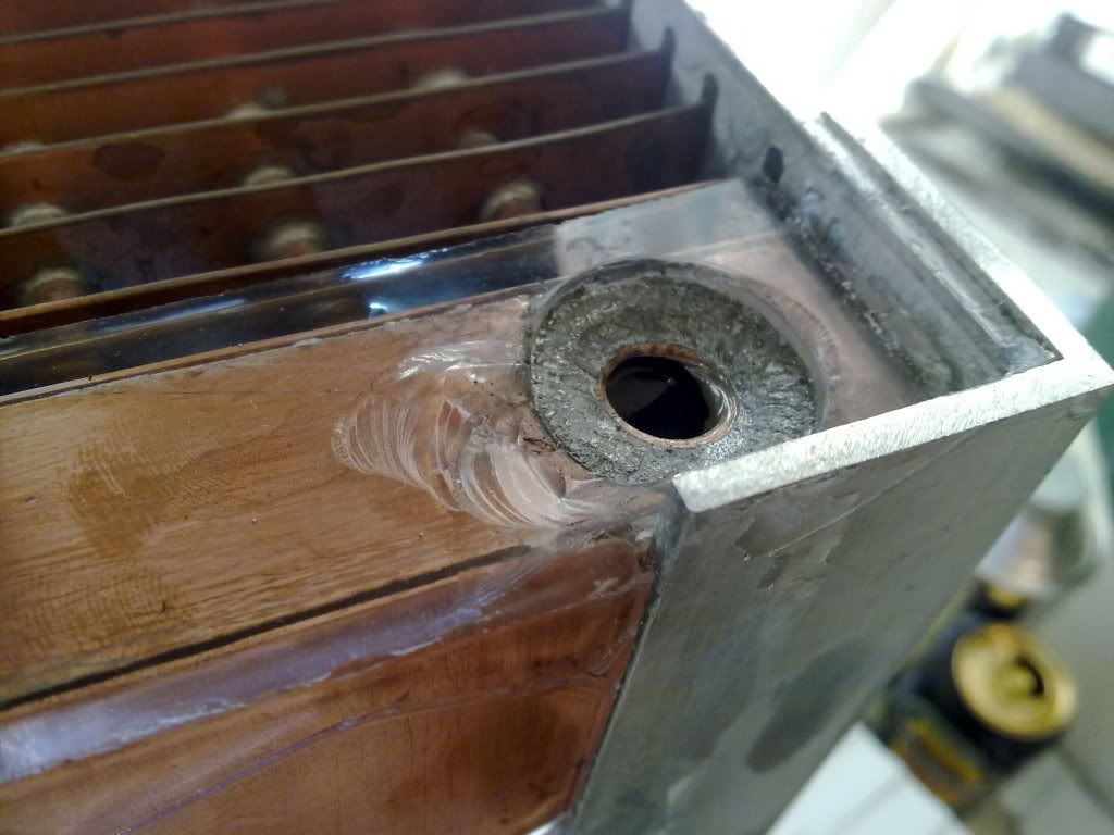
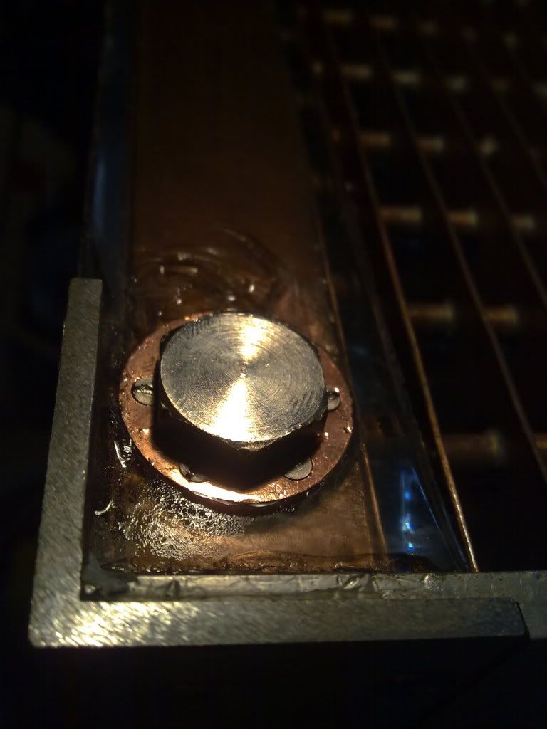
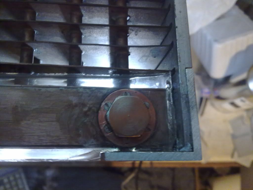
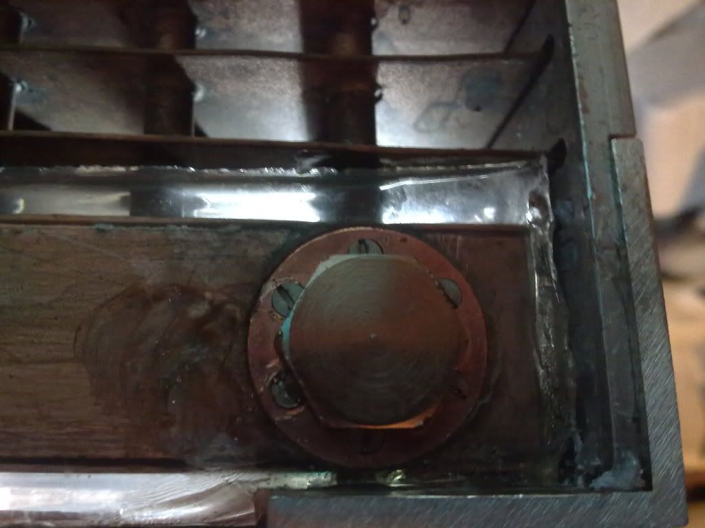
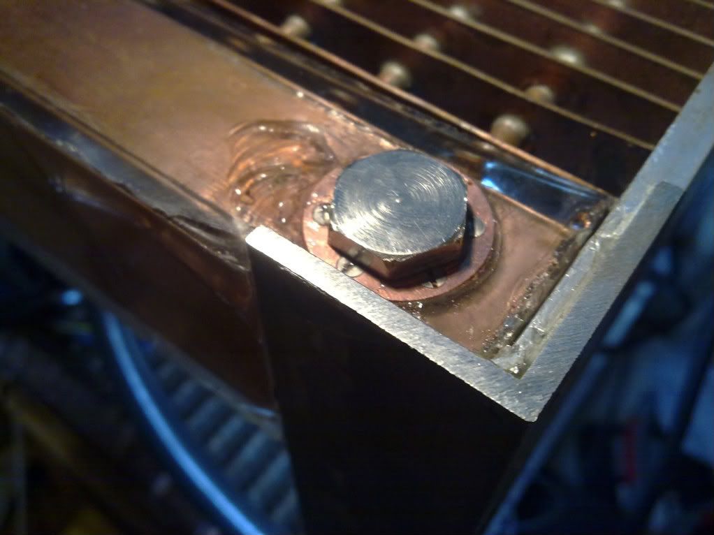
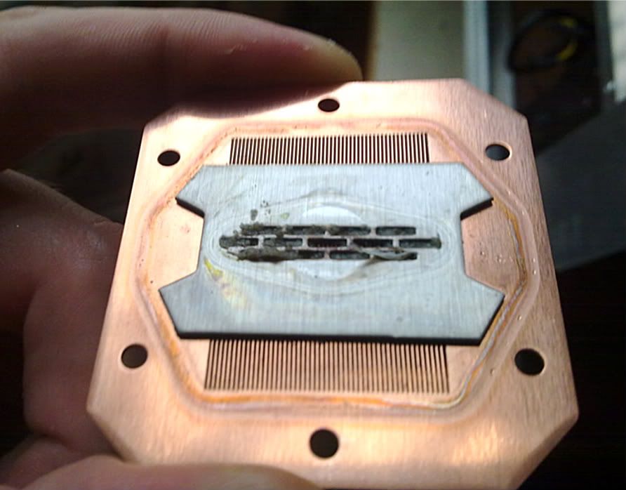
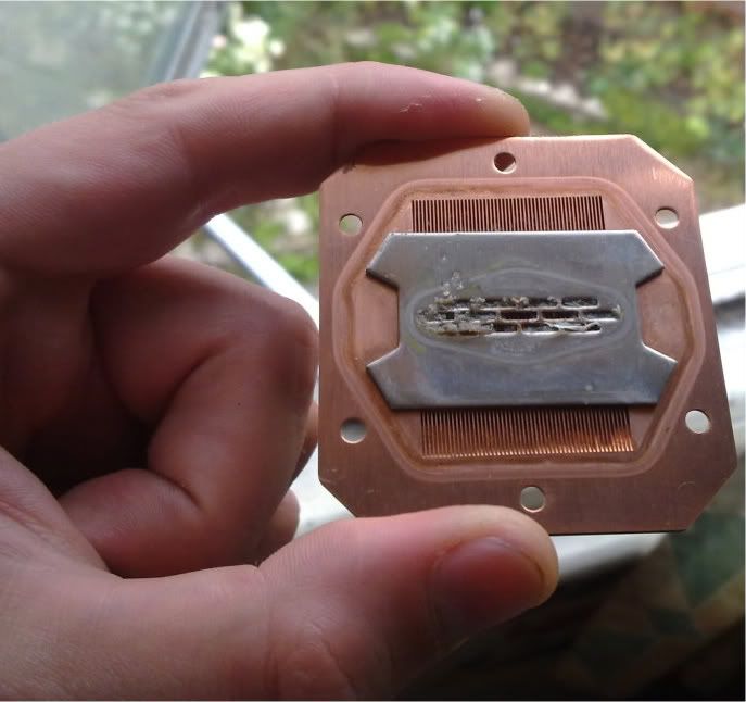
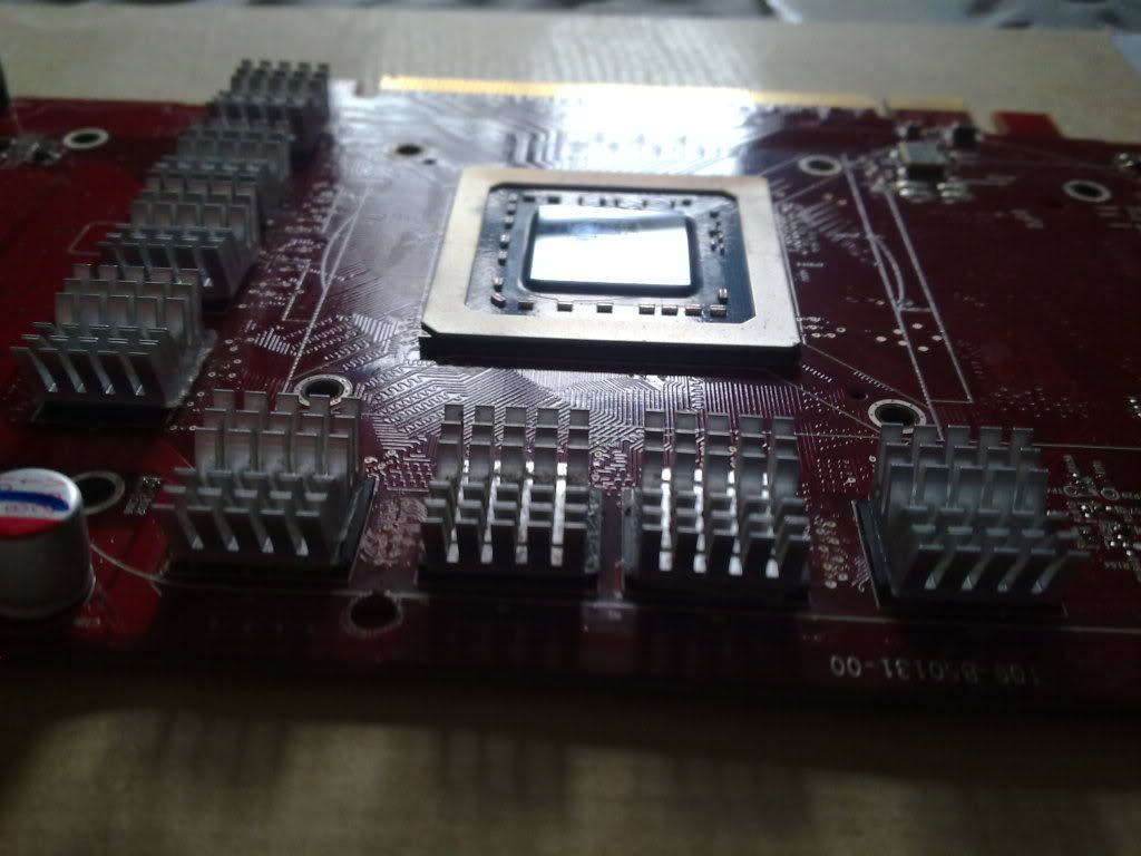
First, I decided to attach the GPU block to the GPU. I bled the loop to take the tubes offf the block, and decided to open the CPU block whilst I was at it...

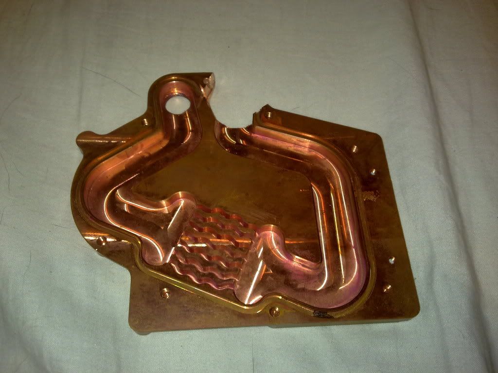
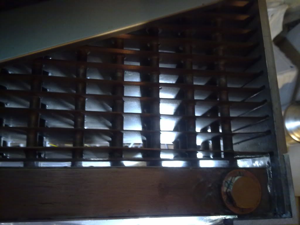
And this is what I found - lots of resin gunk must have come off when I degunked the top fill-port thread (more of that in a minute) and so the previous temperature testing was done with water only flowing into about 1.5 of the 13 impingement slits, cooling only two narrow strips about 5mm wide.

13072010333.jpg


13072010338.jpg


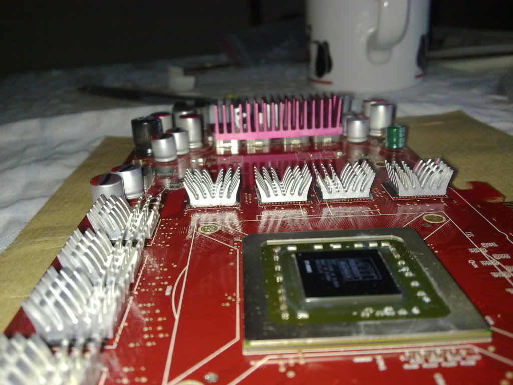
I then added the graphics RAM heatsinks. I was going to cannibalise the single-slot stock cooler on my 4850 as it has nice big sections of widely spaced tall copper pins to cool the VRMs. Except after dremeling about a mm into the stock cooler I realised the stock cooler was just aluminium anodised with copper-coloured dye. Damned charlatans!

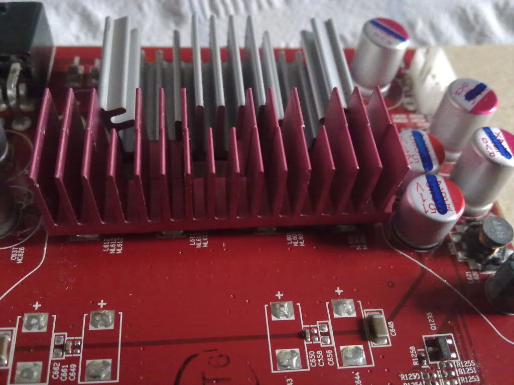
So instead I opted to cannibalise an old VRM heatsink from my old x1900xt (the pinky-crimson coloured bits) as they're widely spaced fins an nice and tall, combined with an aluminium heatsink that's supposed to go onto 8800gtx VRMs I think.

13072010330.jpg


13072010324.jpg


13072010326.jpg
 
Last edited:
Soldato
OP
Joined
13 Mar 2006
Posts
6,712
I then replumbed the loop, started the machine up and did some more temperature testing....

With a degunked HK3.0 waterblock and with the 4850 GPU also in the loop, with the core i750 at 4.2Ghz using 1.43volts vcore it was maxing out at about 55C running intel burn test with the maximum stress I could (about 3.5GB of RAM). :) During gaming (Arma II) it maxed out at around 50C.

Previously, with just the CPU in the loop it had been reaching 72 in intel burn test in my toasty room.

It idles slightly higher now after degunking but with the GPU in the loop, at around 30-32C compared to 26c before.


Sadly, a minor disaster struck. When I cast the thick polyester resin over the top and bottom manifolds/plenums, some resin had managed to find its way under the mold top glued to the top fill-port, and a little bit into the screw thread for the fill cap. I'd tried to dissolve it out using acetone on cotton buds, but with no joy. I stupidly decided to try scraping it out, and in doing so the thread got a bit worn and slightly mangled. Then when I tried to screw in the top fill-port plug it was really tricky to get it to seal, and I needed to screw it in really tight. Then I screwed it in too tight, heard creaking, and the copper fill-port (the 1" diameter x ~5mm cooper ring with the thread inside) sheared at the soldered joint attaching it to the 1mm thick copper wall of the plenum, like so:

PIC SHEARED FILLPORT

17072010359.jpg


It will be fixable, and I'll recast resin into the bits where shards have come off...

So then I did a horrible thing to a very pretty waterblock. As I didn't have access to a lathe or a 11mm odd drill bit, I decided to cannibalise an EK x1900xt fullcover copper waterblock to make a replacement fillport...

pic cannibalised waterblock

17072010382.jpg


After a bit of filing and sanding I was left with this; a shiny new fillport.

17072010342.jpg


17072010354.jpg


17072010360.jpg
 
Soldato
OP
Joined
13 Mar 2006
Posts
6,712
However, there's now resin covering the plenum, so it can't be soldered on. I didn't want to risk it coming off again so I bought a 2mm countersunk drill bit and some m2 countersunk screws, and set at it with my weedy bench drill.

17072010348.jpg


17072010353.jpg


Here's a comparison of the thread on the old and new fill-port:

17072010361.jpg


With 6 screws attaching the fillport to the 1mm thick copper wall it should be able to resist being screwed in. :)

17072010378.jpg


17072010367.jpg


17072010369.jpg


17072010366.jpg


17072010373.jpg


So that's where it's up to at the moment.
 
Soldato
OP
Joined
13 Mar 2006
Posts
6,712
been ages since i last checked for updates, looks like its coming along. Can't wait to see it finished.

Great stuff :)

wow... speechless at the effort, time and skill ...

Cheers guys!

Have it with me now, and getting some work done - mostly sanding off the polyester resin that gunked up the sides and polishing up the aluminium. I've potted the top port with clear polyester resin now so it's watertight again. The cpu block is gunked up again from bits of debris and resin falling innside during sealing the top again - switched over to clear tubes for the moment and had such nice temps for a while as I could see little bits of rubbish flowing through the loop. Now there are no bits of rubbish circulating... Micro-fin blocks act as great sieves. :D

Duesix said:
that things is absolutely huge! how much did it cost in materials?

Yeah, 'tis a large case. Materials costs.. hmm, not sure, around £300-350ish I expect including all the copper plate, 60m of 6mm OD, 4.8mm ID microbore copper tubing, copper bosses, aluminium plate, aluminium right angle, dome head screws, countersunk screws, solder, butane/propane, flux, clear-casting resin, araldite epoxy, sandpaper, vinegar. Had to get quite a few tools as well, but they'll come in handy in future.

Anyhow, next steps are to file down the aluminium frame, fill the grooves in the clear polyester resin and then sand and polish it all down to a crystal clear and mirror-finish. Then it'll be mounting the slot-loading dvd drive and cable-management... cable tidying brackets and sleeving the wires... Shudder. Not looking forward to that. :(
 
Soldato
OP
Joined
13 Mar 2006
Posts
6,712
Update time!

Not a massive update, but took quite a bit of time. I've been tidying up the aluminium frame. It had been covered in polyester resin, which was a nightmare to get rid of. I've sanded the frame down , though it still needs more work and there are still some small blemishes and scratches that I need to get rid of. I'm not 100% how necessary a mirror-shine is, since I plan on anodising the frame either gun-metal/carbon grey or black.

Anyhow, here's some pictures. Enjoy!

P1000954.jpg


P1000957.jpg


And here's the back of it. The slits are for the 37 copper heatfins to sit in. They'll later be set into these groves, probably using polyester resin.

P1000965.jpg


Here's the right-sided upright aluminium angle leg. The row of 9 holes is to attach to the copper wall of the radiator. The 3 finger cuts set into the top and bottom are to accommodate the copper pipes of the radiator.

The slit is for a slimline slot-loading DVD drive to sit behind. Still planning on a no-5.25" design for the front.

P1000968.jpg


P1000971.jpg


P1000972.jpg


Here it is with the counter-sunk screws in. The one on the bottom left is stuck in place - think I must have forgotten to tap all the way through and it's got caught in the aluminium. :( I'll have to drill it out on the bench press next time I go visit my folks. Until then I can't sand around it or disassemle those two pieces. I still need to adjust the countersunk holes slightly to get the screws exactly flush, but most of them are level with the surface.

P1000976.jpg


P1000977.jpg


P1000978.jpg


P1000980.jpg


P1000981.jpg


P1000983.jpg


And here it is assembled:

P1000987.jpg


Might take some better photos later on.
 
Back
Top Bottom