Soldato
- Joined
- 13 Mar 2006
- Posts
- 6,712
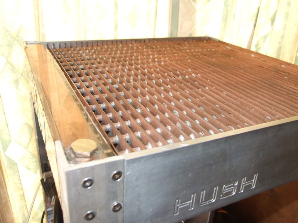
Project: Hush!
Taster pics:
Update Links:
http://forums.overclockers.co.uk/showpost.php?p=14258086&postcount=2
http://forums.overclockers.co.uk/showpost.php?p=14258092&postcount=3
http://forums.overclockers.co.uk/showpost.php?p=14300824&postcount=55
http://forums.overclockers.co.uk/showpost.php?p=14579041&postcount=81
http://forums.overclockers.co.uk/showpost.php?p=15892922&postcount=149
http://forums.overclockers.co.uk/showpost.php?p=15892933&postcount=150
http://forums.overclockers.co.uk/showpost.php?p=16342323&postcount=175
http://forums.overclockers.co.uk/showpost.php?p=16342356&postcount=176
http://forums.overclockers.co.uk/showpost.php?p=16798481&postcount=214
http://forums.overclockers.co.uk/showpost.php?p=16798513&postcount=216
http://forums.overclockers.co.uk/showpost.php?p=16798550&postcount=217
http://forums.overclockers.co.uk/showpost.php?p=16807037&postcount=232
http://forums.overclockers.co.uk/showpost.php?p=17105511&postcount=241
----------------------------------------
Hello all. I've started making a large passive radiator/case. I've been working on it for a while, but since the design is quite complicated I thought I'd wait until it got to a recognisable, likely to work(!) stage before starting the build log.
I have had an innovatek Konvekt-o-matik before selling it on members' market, but from what I've heard you really need a shedload of them to handle high heatloads. Plus, they're expensive (~£80/6tubes), bulky and the design is flawed in my opinion - aluminium, made for 8mm ID tubing, and by their design the more of them you add the larger the pressure loss - 8mm inlet splits to 8mm tubes running in parallel.
So I figured I'd make my own;")
copper,
designed for 7/16" or 1/2" tubing,
minimise pressure loss by matching resistance of the tubes to 1/2" tubing,
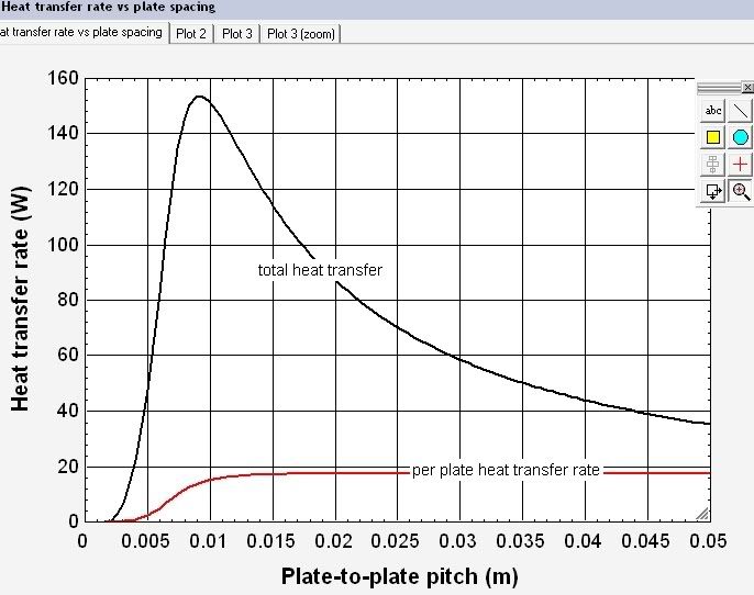
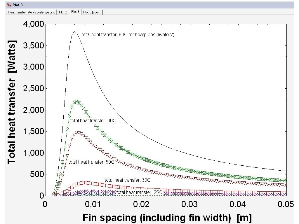
massive amount of surface area (since it's the equivalent of an Aga it needs to have headway for extra heatload),
wide fin spacing and compact enough to be self-contained within a case.
The case is going to be approximately 45cm wide x 40cm deep x 46cm tall + height of castors. So it's slightly smaller than a mountain mods UFO (45x45x45)
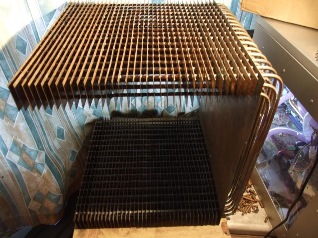
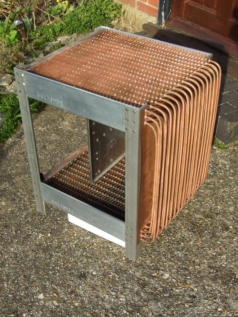
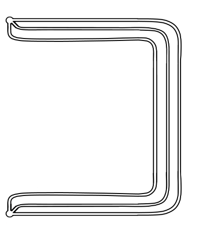
The top, far side of the case (the non-window side panel on a normal case) and the bottom will be made up of a large finned copper radiator, hopefully with enough surface area and passive airflow to run completely passive, with air rising up through the case. I wish I was competent enough with google sketchup to draw a detailed plan, but it just seems a nightmare because of the design, so I'm afraid I've largely stuck to hand-drawn sketches. Here's a very rough idea of what the passive radiator element of the case will look like.
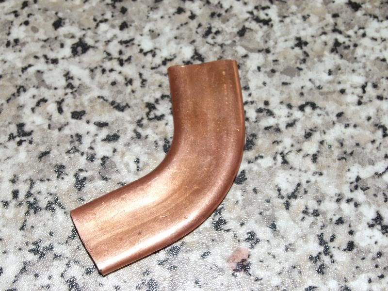
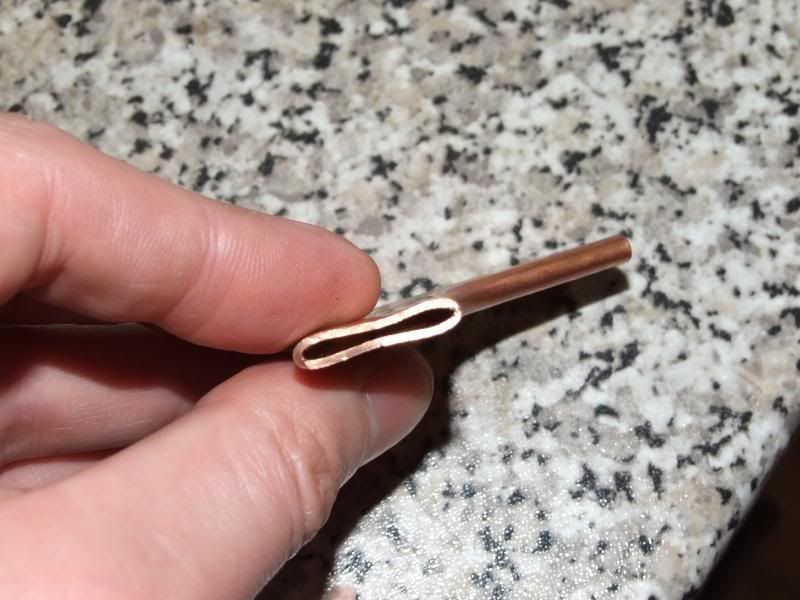
Initially I was going to use 30 metres of standard 15mm outer diameter half-hard pipe used in home plumbing and flatten it as in normal watercooling radiators, but after buying a small sample (a gentle elbow bend) and trying to flatten it I realised it's very tricky to get an even inner channel, and it would take forever to flatten 30m of the half-hard stuff...
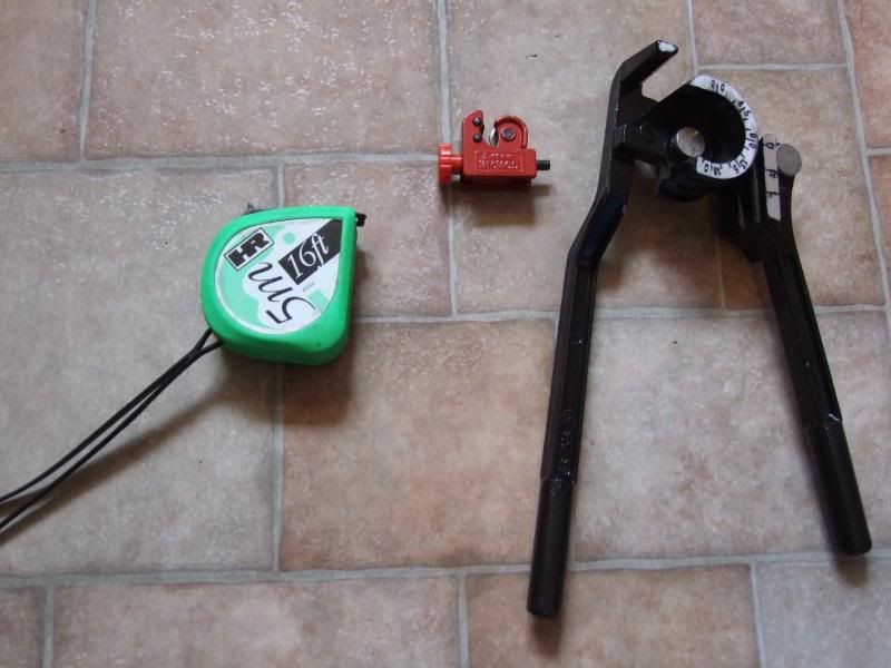
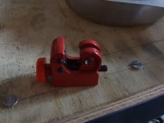
After scouring around to find a cheap source of soft copper pipe I found on ebay what was listed as 9m of soft 15mm outer diameter, 0.4mm-thick-walled copper pipe used as gas lines in boats and motorhomes, and being the only bidder got it dirt cheap.. I picked up an adjustable pipe cutter (3-22mm) for a few quid and measured and cut 130cm lengths. Turns out I was sold around 14m, so had 10 x 130cm, and an offcut.
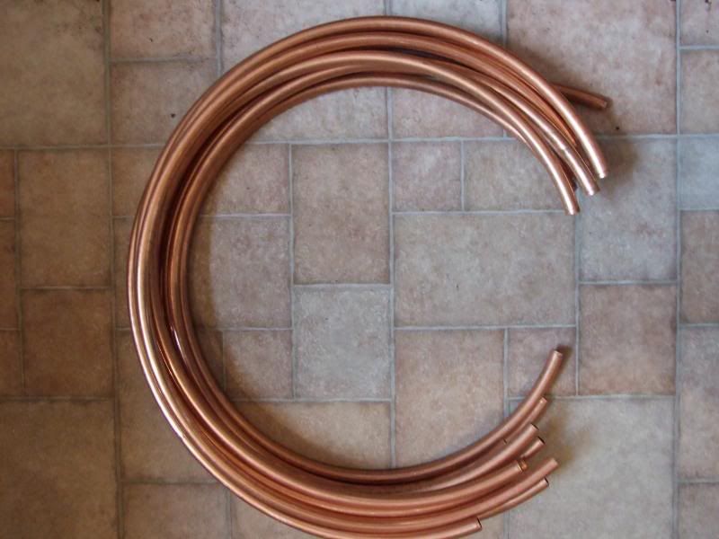
Unfortunately, though slightly easier than the the half-hard copper, the walls of the stuff I got was 1.5mm so it was still a nightmare, and still came out uneven in cross-section and took ages to flatten. I also found it's expensive stuff to get any more - about £80 for 25m. I'll find a good use for it later on though.
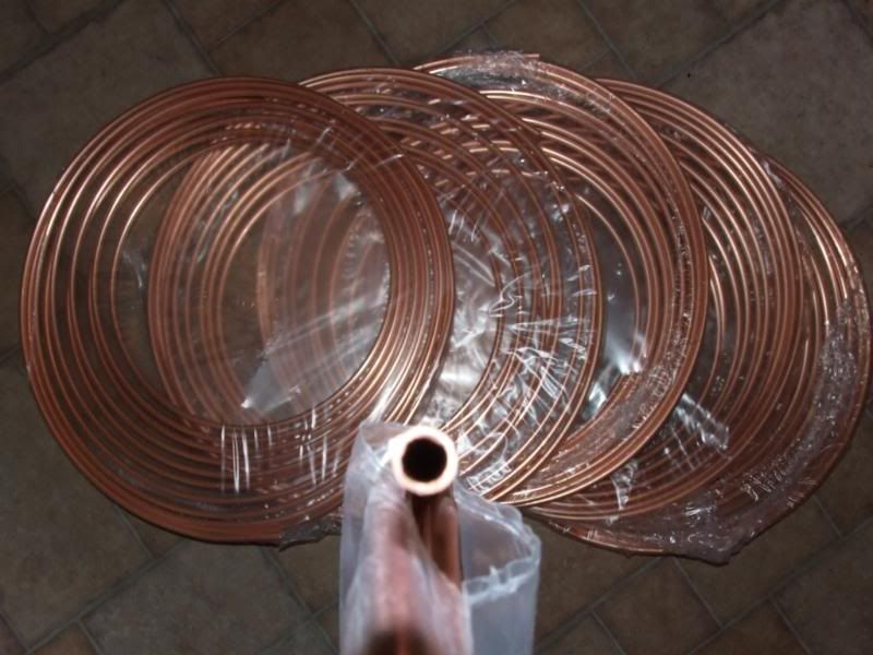
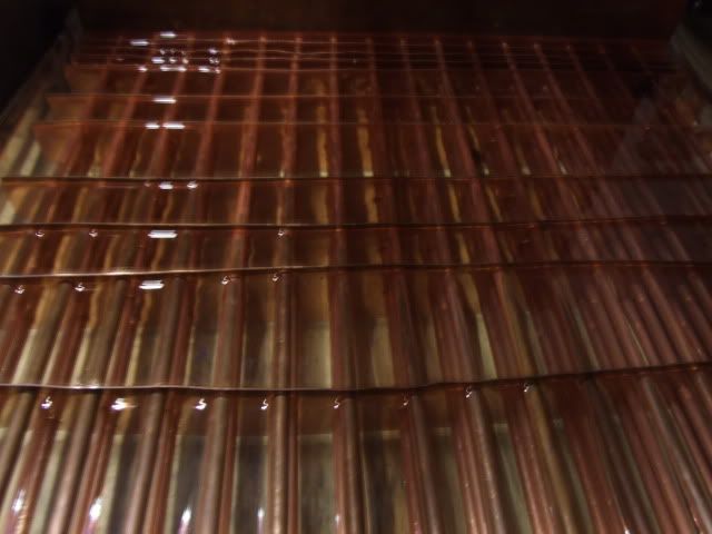
So, time for plan B. I managed to find a site selling 10m x 6mm outer diameter, 4.8mm inner diameter soft microbore copper tubing, so I picked up 6 rolls for ~£42 inc p&p
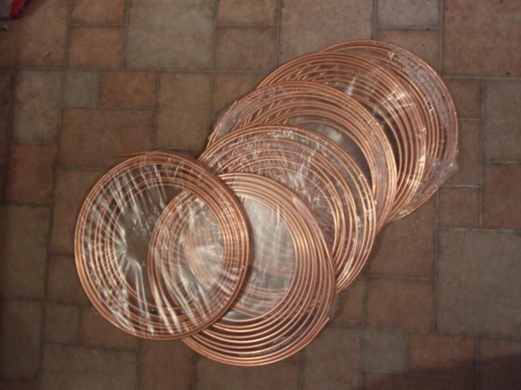
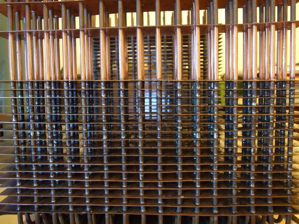
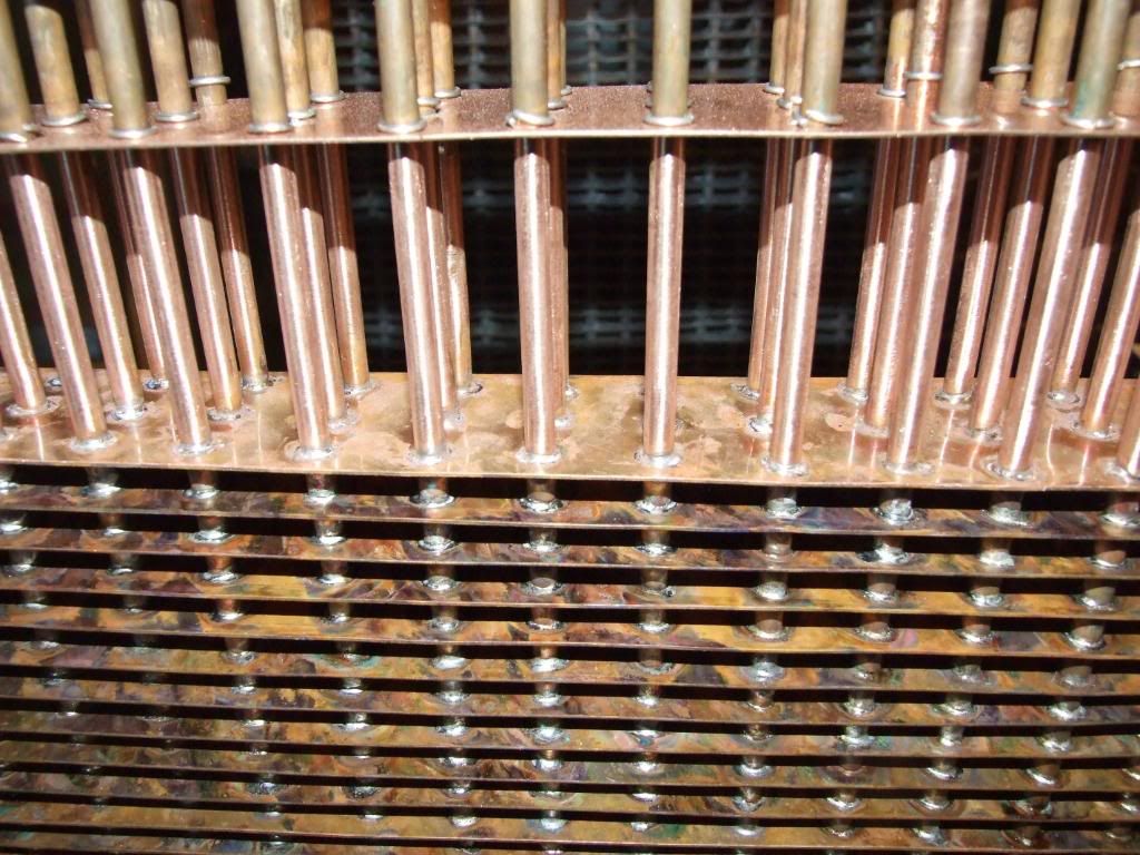
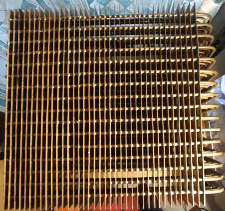
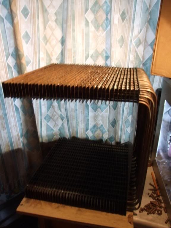
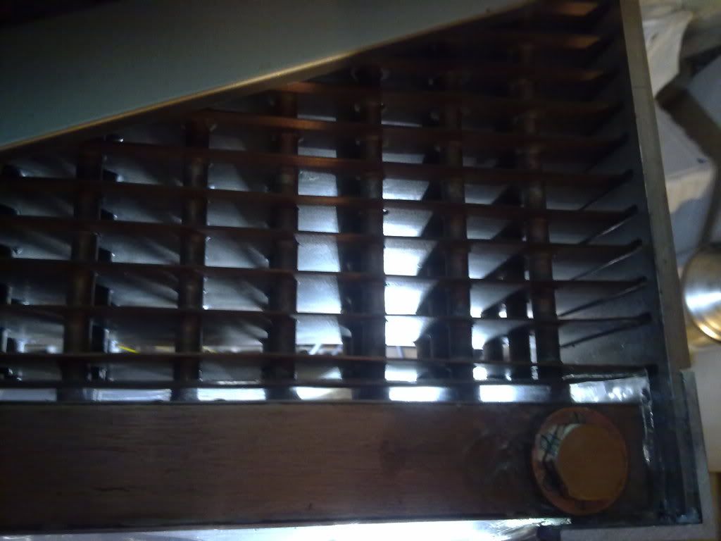
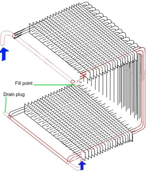
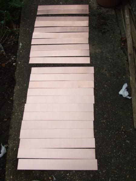
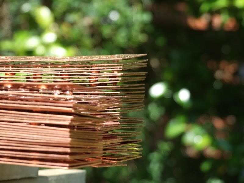
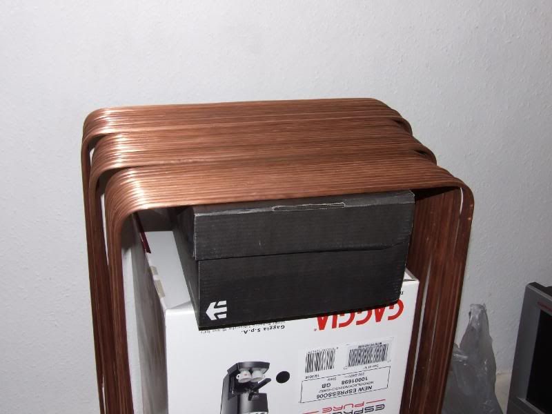
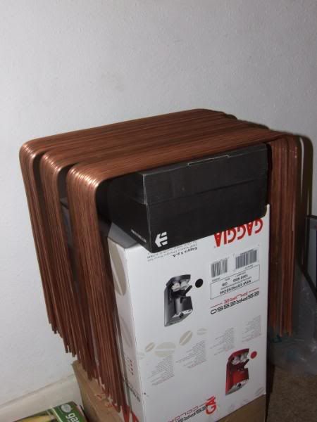
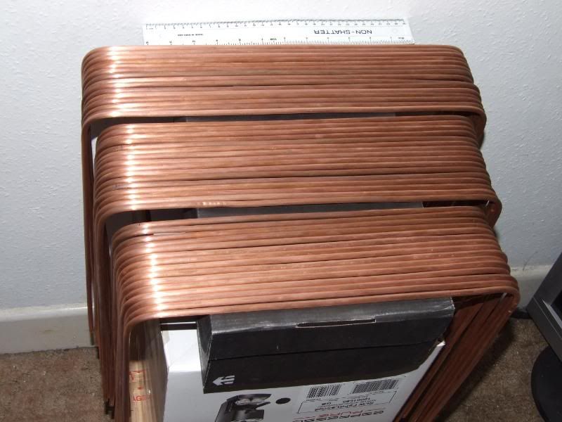
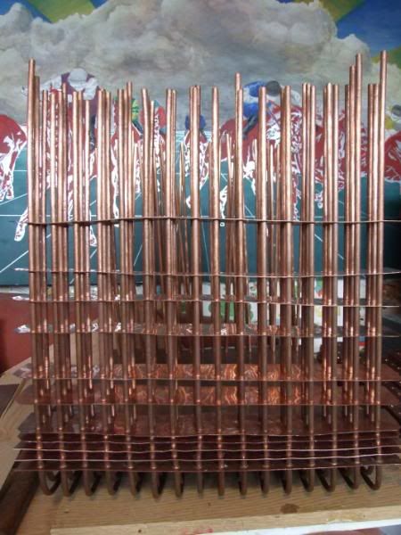
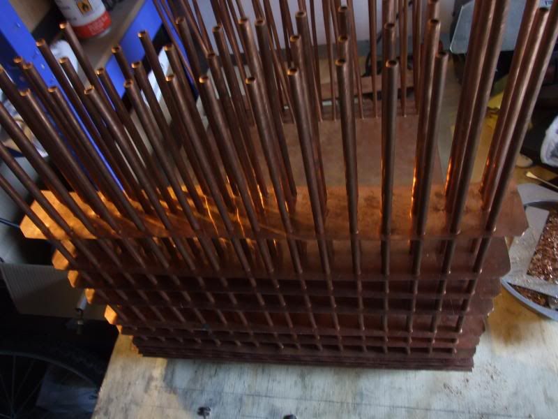
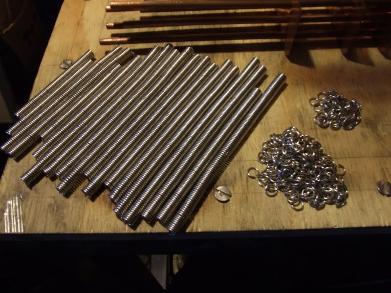
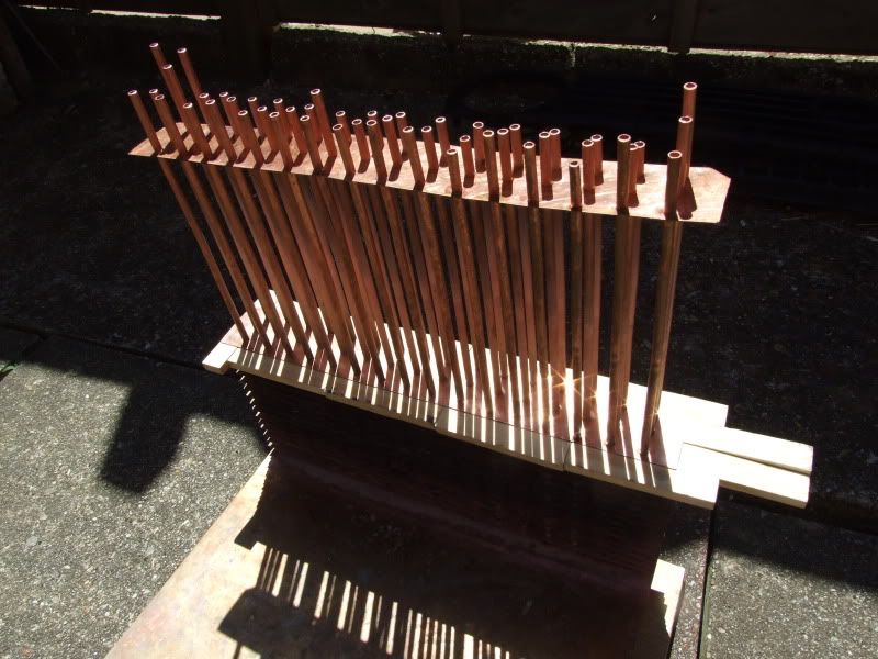
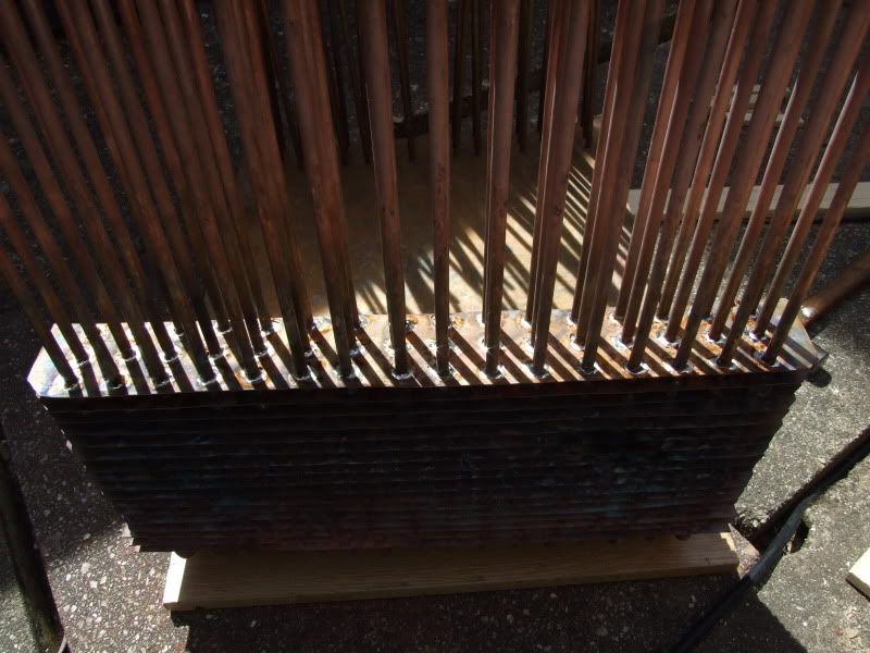
I then unrolled them, measured and cut into 48 lengths - 16 x 120cm, 16 x 125cm and 16 x 130cm - the difference is because the 48 tubes will be arranged as so, so the outer tubes need to be a bit longer:
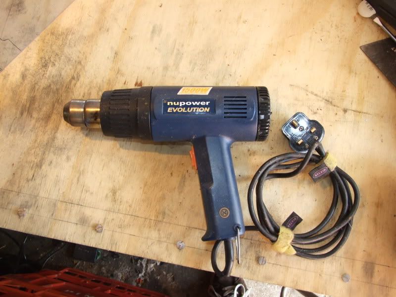
The microbore copper is so soft it's very easy to bend and straighten, though it's tricky to get 130cm lengths completely straight. It work-hardens and quickly becomes difficult to bend, though it can be annealed again by sticking it over a gas hob.
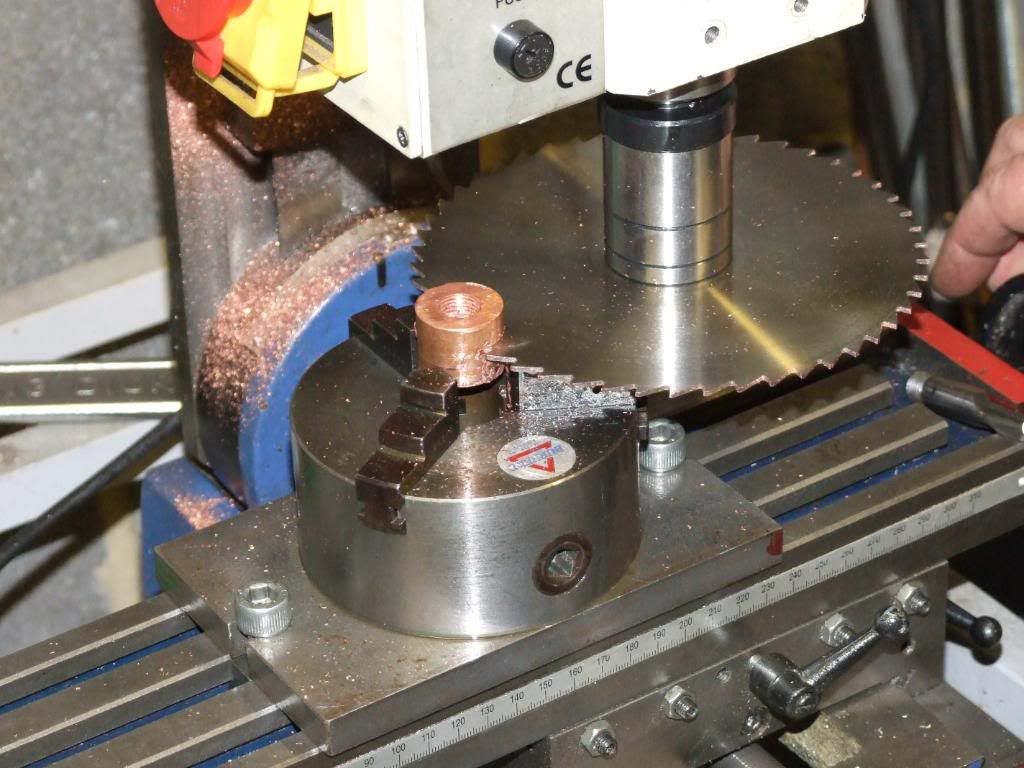
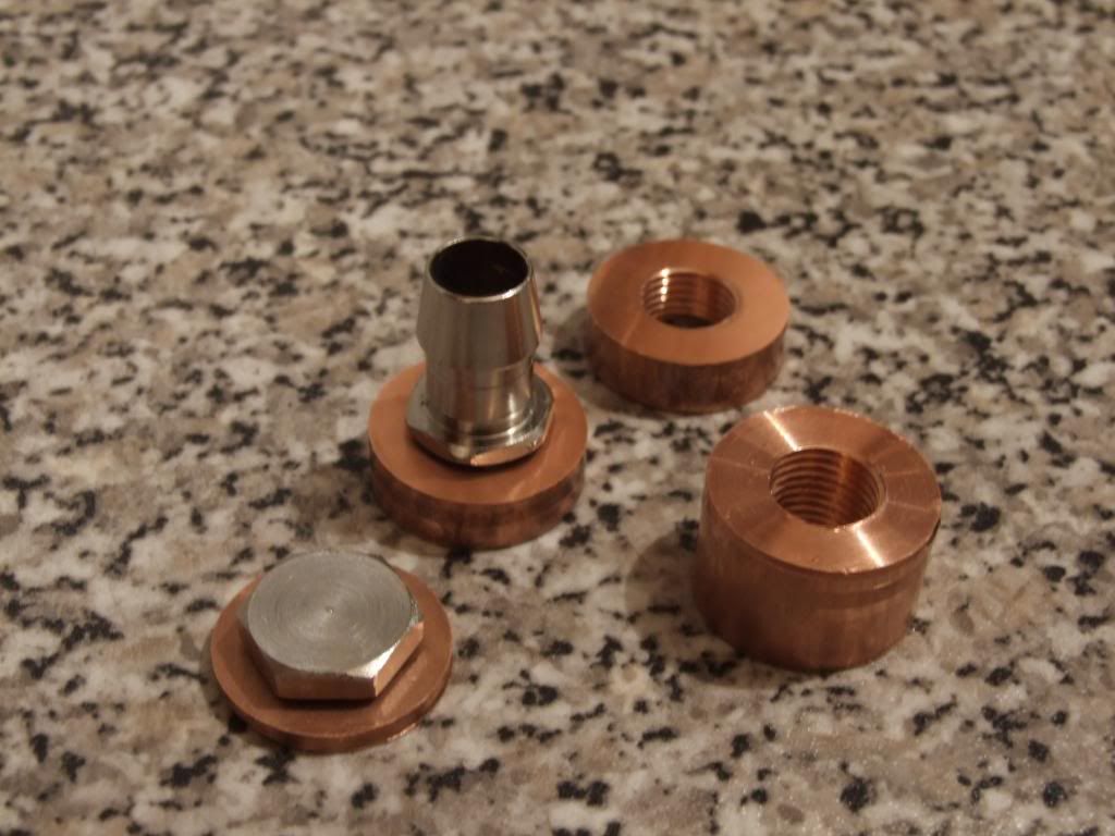
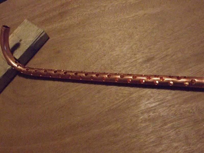
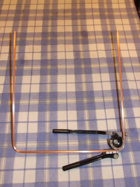
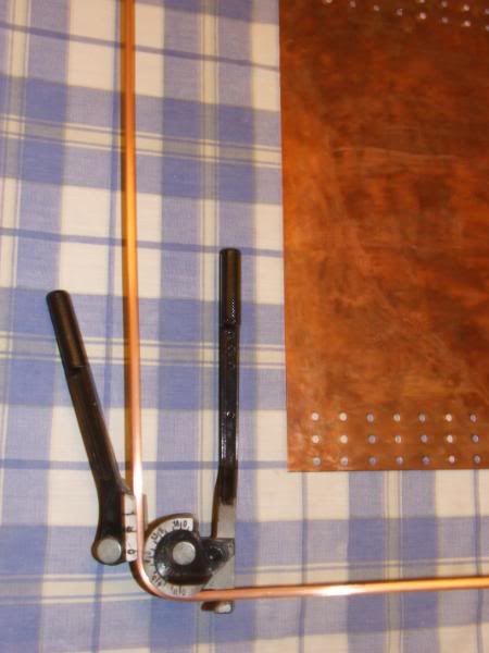
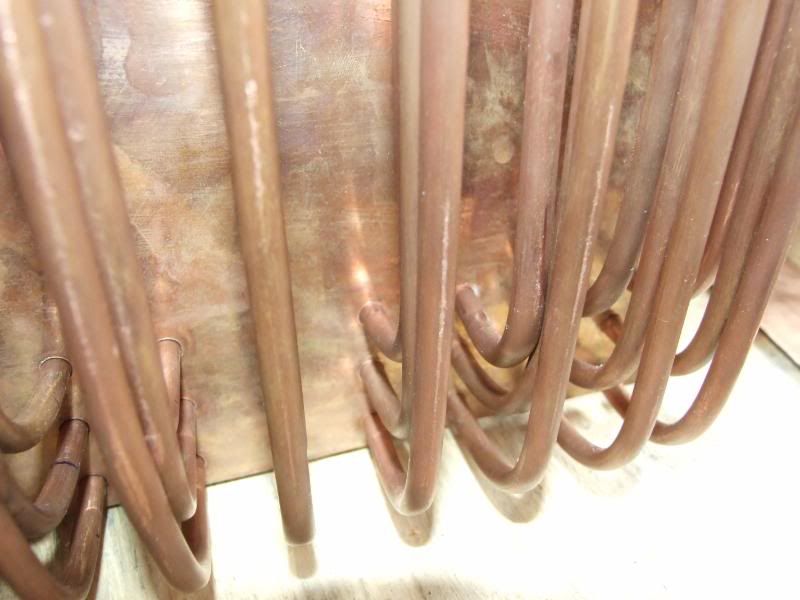
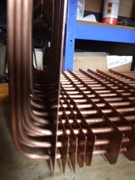
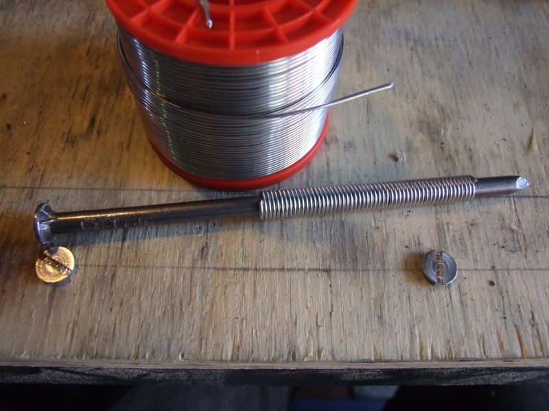
Anyhow, I had originally planned to use some of the 15mm pipe I had for the end pipes distributing the water to the 6mm copper tubes. It has a 12mm inner diameter so is a pretty good match for either 7/16" or 1/2" tubing.. After straightening one of the 130cm lengths I bent it to a hook shape over a rolling pin, which was quite tricky. I then cut it to a rough length and measured out the 48 x 6mm holes for the microbore pipe to connect to.
The pipes will have to do a bit of bending at the ends, but hopefully with the small bore pipebender I got this won't be too much trouble, though in reality it'll probably be very very frustrating, since the pipe needs to be bent after the copper fins have been pushed into place.
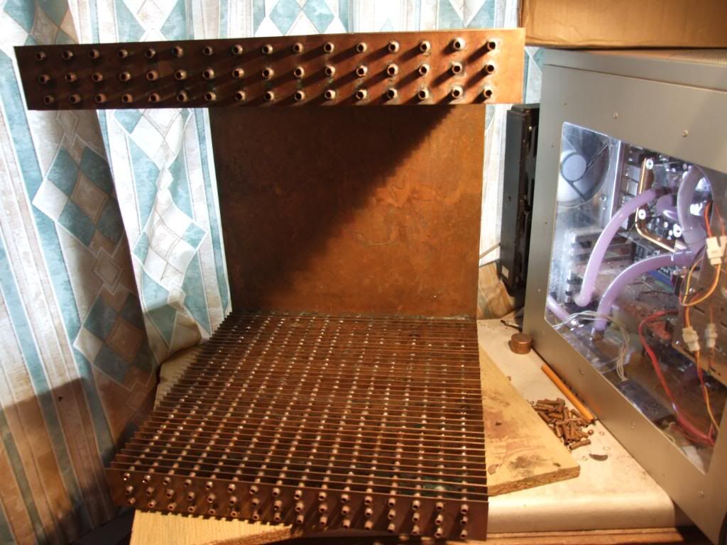
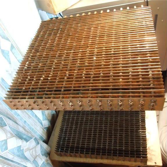
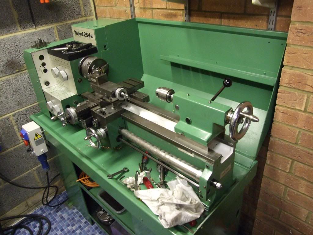
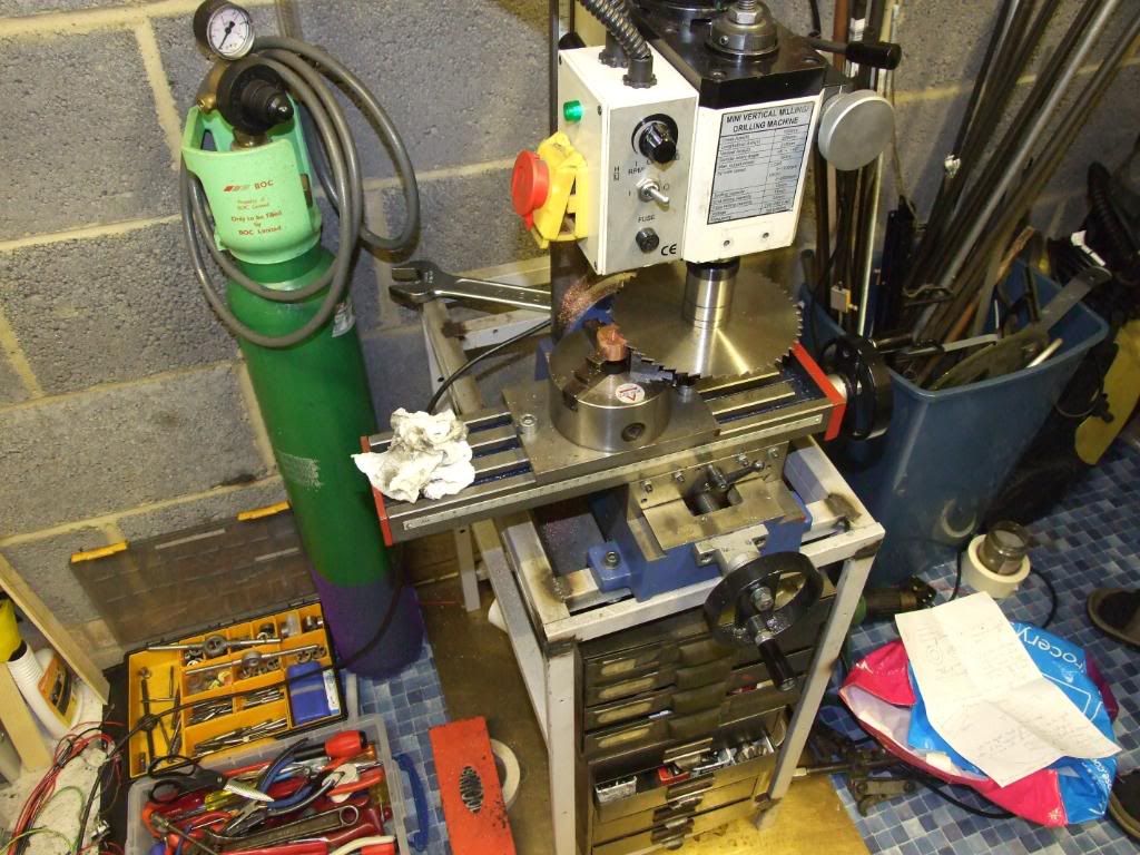
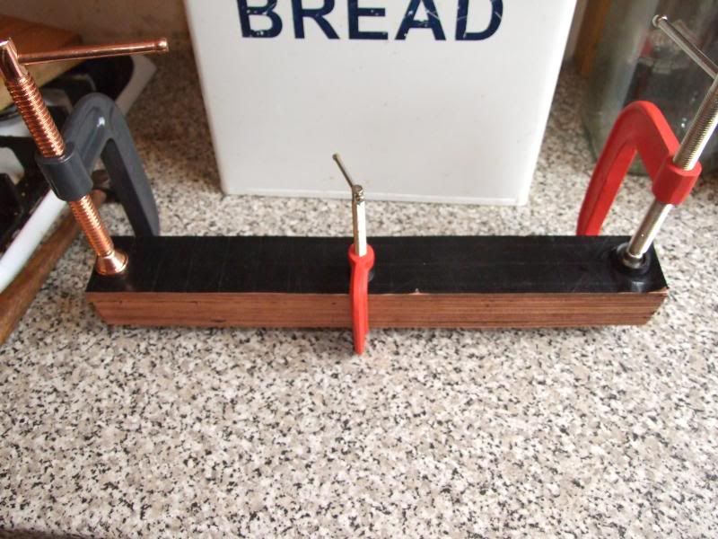
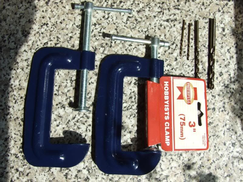
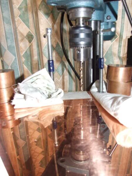
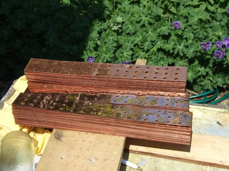
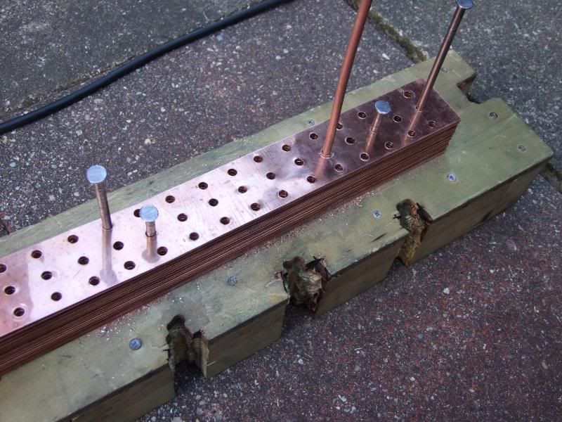
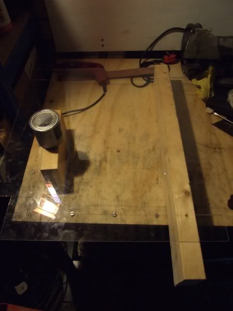
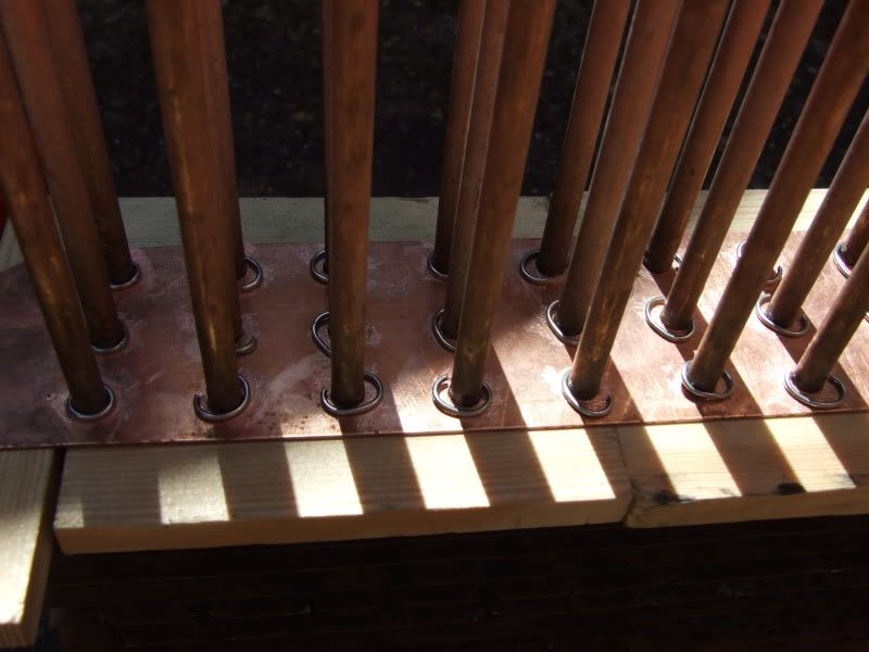
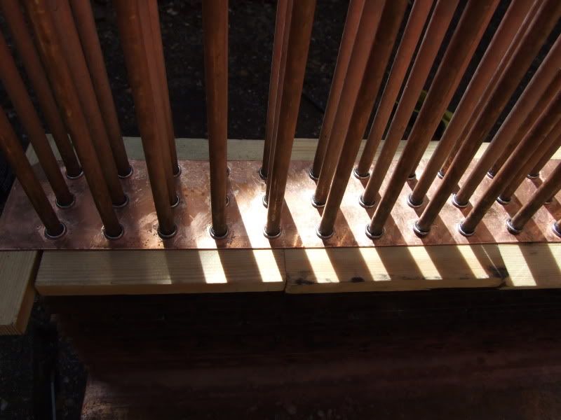
After lots and lots of drilling here are the radiator end pieces. This would have been so much easier if I had a bench drill and a vice, but as I didn't at this stage I had to improvise:
Plan for pipes joining distributor end tube - side view

After all that drilling my plans changed (always the best way for a project to go horribly wrong ). I managed to source some cheap copper sheet for around a quarter of the going rate from shopping around
 , and for a small extra charge the seller was even willing to cut it with a metal shear into lots of 395mm x 50mm strips for the heatfins. So the dimensions of the whole thing changed, and the drilled pipes were now the wrong size. Ho hum.
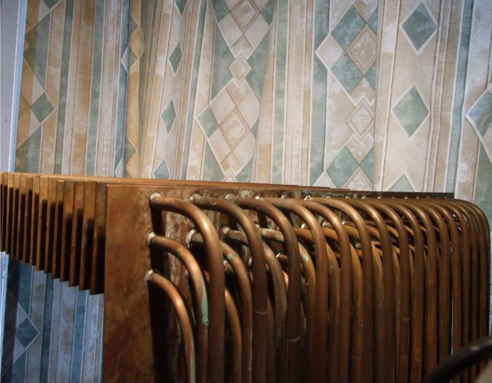
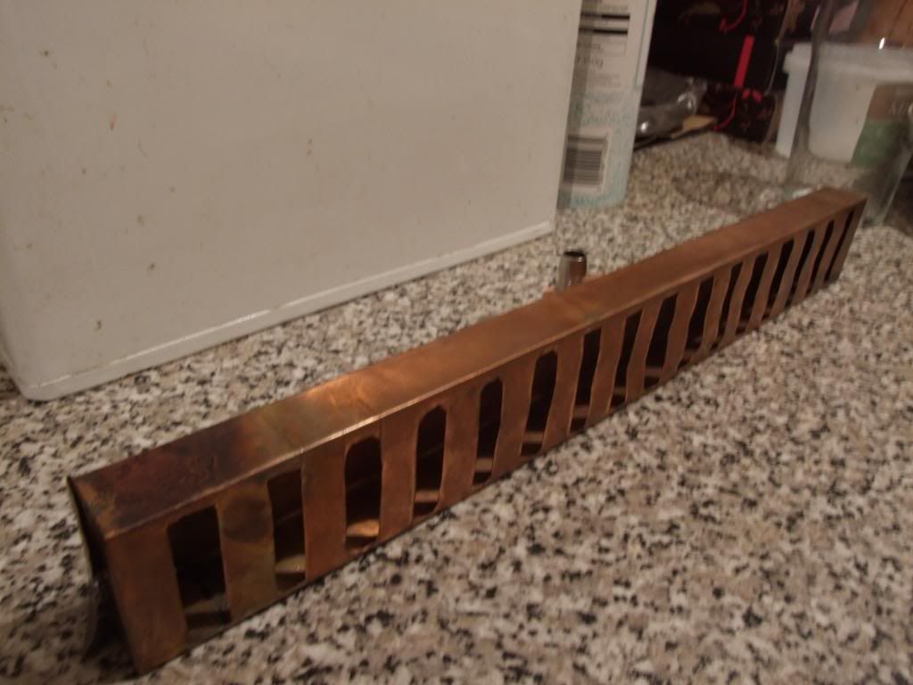
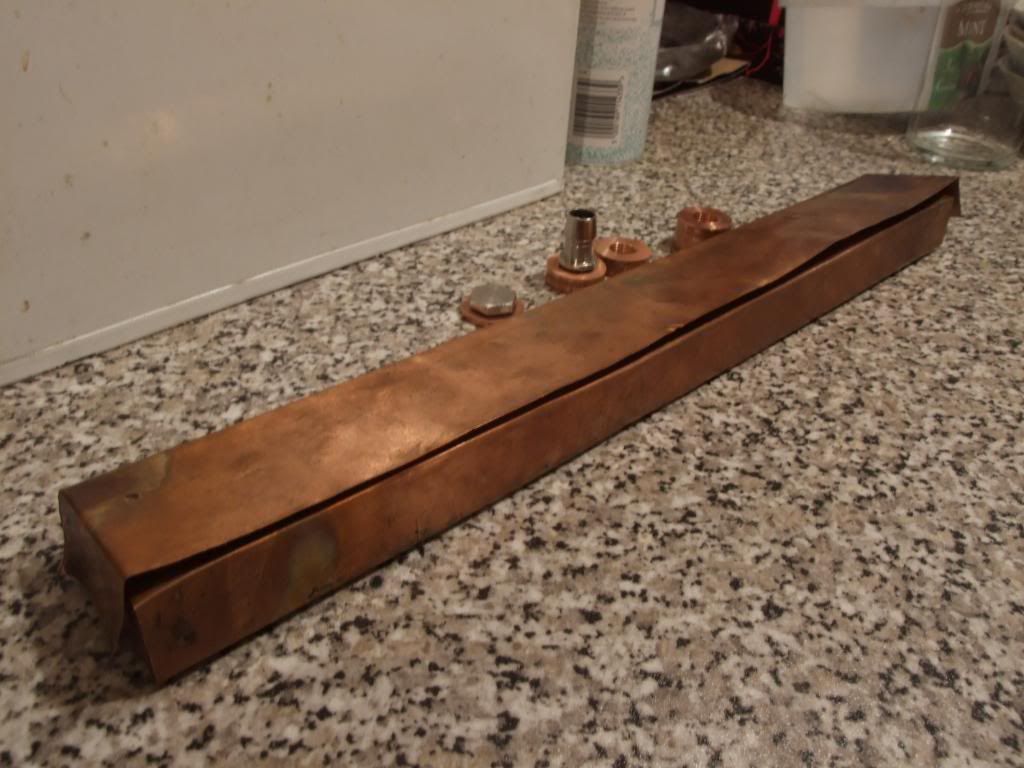
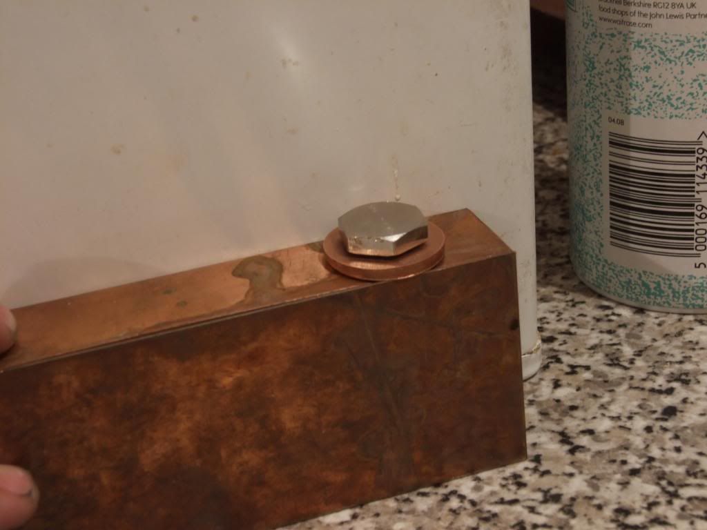
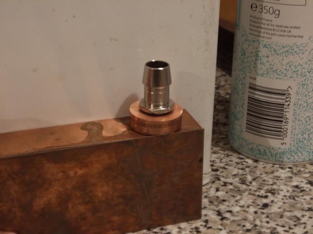
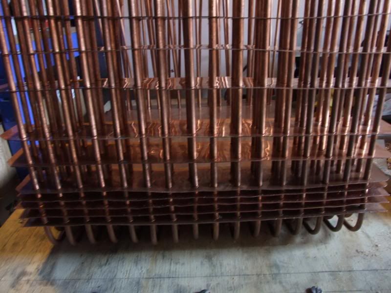
I now plan to instead use a plenum akin to those in standard pc radiators. They serve a purpose in allowing a reservoir of water so that water going down the tubes doesn't cause unequal flow between pipes at the inlet end compared to the other. More importantly, it would be easier to make rather than many cramped, fiddly bends for the tube ends.
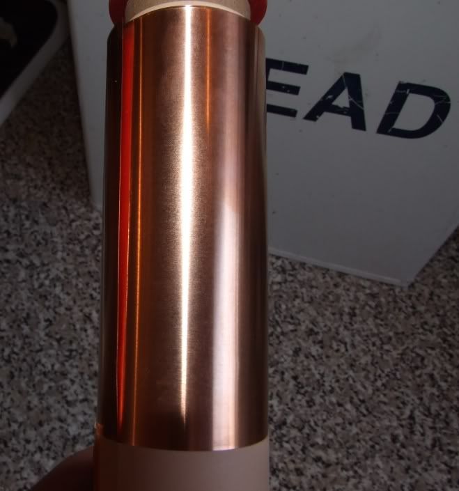
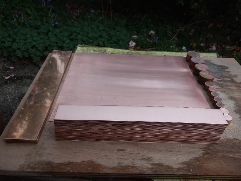
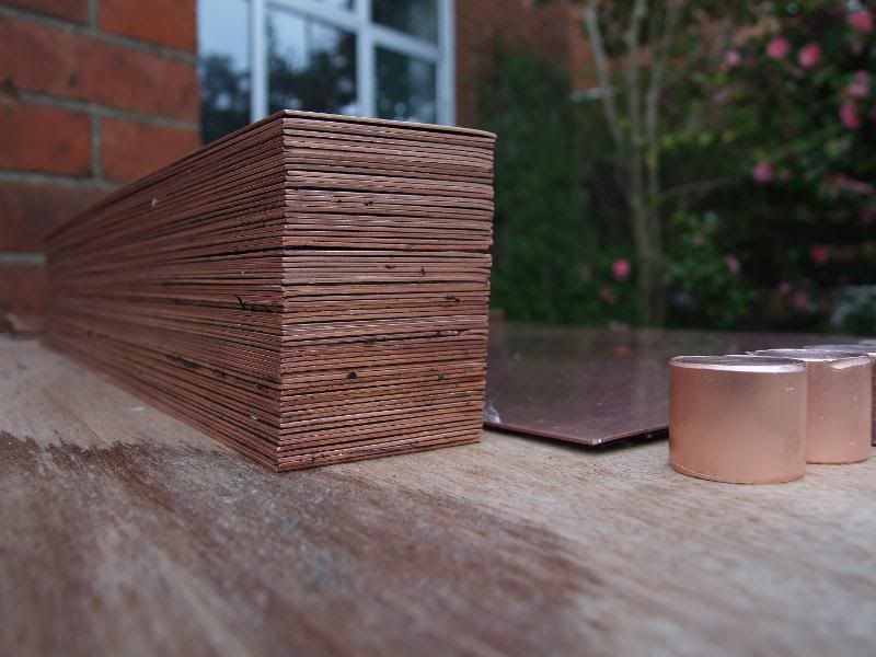
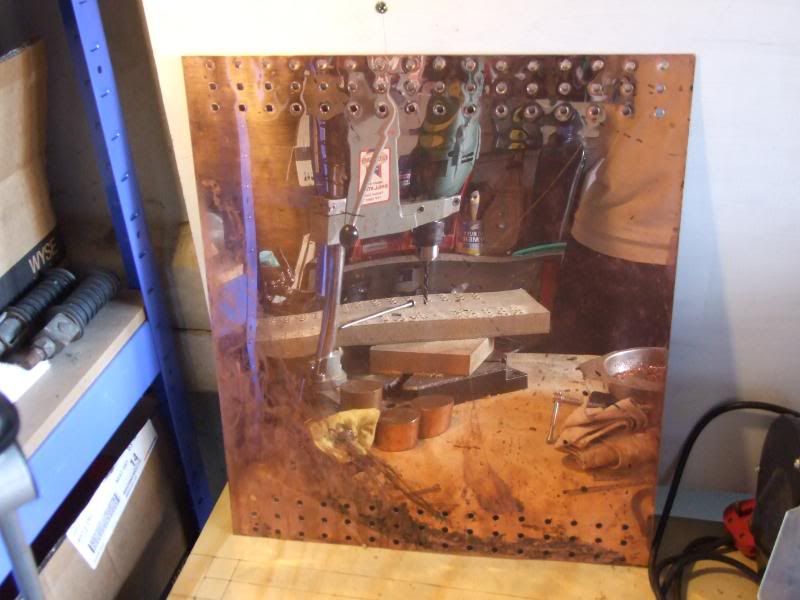
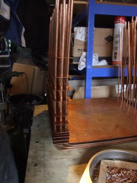
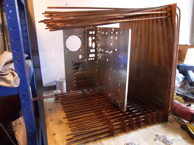
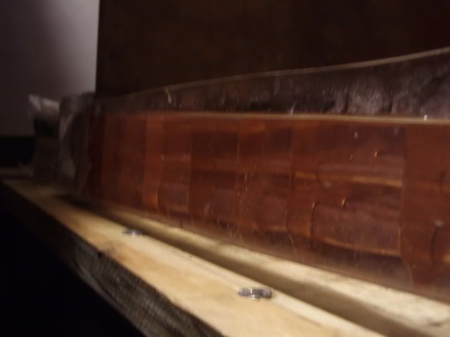
Here's a picture of the copper. It had been left lying around in a scrapyard for God knows how many years, and was a bit scratched here and there, but should clean up nicely enough.
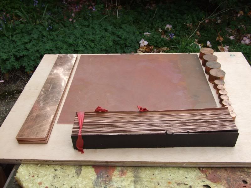
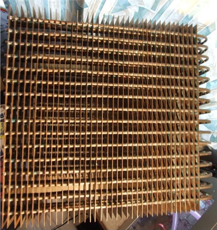
In the pic are a 39.5cm x 45.5 cm x0.9mm copper sheet for the side wall the tubes go through, 63 of 39.5cm x 5cm x 0.9mm copper strips to be used as heatfins, and 16 of 7.5cm x 39.5cm strips (additional 39.5cm x 5cm heatfins have since been cut from them). There's also some copper bosses (solid cylinders) that I nmay put to good use.
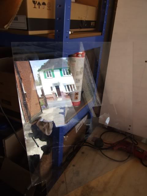
After cleaning
Taster pics:
Update Links:
http://forums.overclockers.co.uk/showpost.php?p=14258086&postcount=2
http://forums.overclockers.co.uk/showpost.php?p=14258092&postcount=3
http://forums.overclockers.co.uk/showpost.php?p=14300824&postcount=55
http://forums.overclockers.co.uk/showpost.php?p=14579041&postcount=81
http://forums.overclockers.co.uk/showpost.php?p=15892922&postcount=149
http://forums.overclockers.co.uk/showpost.php?p=15892933&postcount=150
http://forums.overclockers.co.uk/showpost.php?p=16342323&postcount=175
http://forums.overclockers.co.uk/showpost.php?p=16342356&postcount=176
http://forums.overclockers.co.uk/showpost.php?p=16798481&postcount=214
http://forums.overclockers.co.uk/showpost.php?p=16798513&postcount=216
http://forums.overclockers.co.uk/showpost.php?p=16798550&postcount=217
http://forums.overclockers.co.uk/showpost.php?p=16807037&postcount=232
http://forums.overclockers.co.uk/showpost.php?p=17105511&postcount=241
----------------------------------------
Hello all. I've started making a large passive radiator/case. I've been working on it for a while, but since the design is quite complicated I thought I'd wait until it got to a recognisable, likely to work(!) stage before starting the build log.
I have had an innovatek Konvekt-o-matik before selling it on members' market, but from what I've heard you really need a shedload of them to handle high heatloads. Plus, they're expensive (~£80/6tubes), bulky and the design is flawed in my opinion - aluminium, made for 8mm ID tubing, and by their design the more of them you add the larger the pressure loss - 8mm inlet splits to 8mm tubes running in parallel.
So I figured I'd make my own;
copper,
designed for 7/16" or 1/2" tubing,
minimise pressure loss by matching resistance of the tubes to 1/2" tubing,
massive amount of surface area (since it's the equivalent of an Aga it needs to have headway for extra heatload),
wide fin spacing and compact enough to be self-contained within a case.
The case is going to be approximately 45cm wide x 40cm deep x 46cm tall + height of castors. So it's slightly smaller than a mountain mods UFO (45x45x45)
The top, far side of the case (the non-window side panel on a normal case) and the bottom will be made up of a large finned copper radiator, hopefully with enough surface area and passive airflow to run completely passive, with air rising up through the case.
I wish I was competent enough with google sketchup to draw a detailed plan, but it just seems a nightmare because of the design, so I'm afraid I've largely stuck to hand-drawn sketches. Here's a very rough idea of what the passive radiator element of the case will look like.
Initially I was going to use 30 metres of standard 15mm outer diameter half-hard pipe used in home plumbing and flatten it as in normal watercooling radiators, but after buying a small sample (a gentle elbow bend) and trying to flatten it I realised it's very tricky to get an even inner channel, and it would take forever to flatten 30m of the half-hard stuff...
After scouring around to find a cheap source of soft copper pipe I found on ebay what was listed as 9m of soft 15mm outer diameter, 0.4mm-thick-walled copper pipe used as gas lines in boats and motorhomes, and being the only bidder got it dirt cheap.
. I picked up an adjustable pipe cutter (3-22mm) for a few quid and measured and cut 130cm lengths. Turns out I was sold around 14m, so had 10 x 130cm, and an offcut.
Unfortunately, though slightly easier than the the half-hard copper, the walls of the stuff I got was 1.5mm so it was still a nightmare, and still came out uneven in cross-section and took ages to flatten. I also found it's expensive stuff to get any more - about £80 for 25m. I'll find a good use for it later on though.
So, time for plan B. I managed to find a site selling 10m x 6mm outer diameter, 4.8mm inner diameter soft microbore copper tubing, so I picked up 6 rolls for ~£42 inc p&p
I then unrolled them, measured and cut into 48 lengths - 16 x 120cm, 16 x 125cm and 16 x 130cm - the difference is because the 48 tubes will be arranged as so, so the outer tubes need to be a bit longer:
The microbore copper is so soft it's very easy to bend and straighten, though it's tricky to get 130cm lengths completely straight. It work-hardens and quickly becomes difficult to bend, though it can be annealed again by sticking it over a gas hob.
Anyhow, I had originally planned to use some of the 15mm pipe I had for the end pipes distributing the water to the 6mm copper tubes. It has a 12mm inner diameter so is a pretty good match for either 7/16" or 1/2" tubing.. After straightening one of the 130cm lengths I bent it to a hook shape over a rolling pin, which was quite tricky. I then cut it to a rough length and measured out the 48 x 6mm holes for the microbore pipe to connect to.
The pipes will have to do a bit of bending at the ends, but hopefully with the small bore pipebender I got this won't be too much trouble, though in reality it'll probably be very very frustrating, since the pipe needs to be bent after the copper fins have been pushed into place.
After lots and lots of drilling here are the radiator end pieces. This would have been so much easier if I had a bench drill and a vice, but as I didn't at this stage I had to improvise:
Plan for pipes joining distributor end tube - side view
After all that drilling my plans changed (always the best way for a project to go horribly wrong
). I managed to source some cheap copper sheet for around a quarter of the going rate from shopping around, and for a small extra charge the seller was even willing to cut it with a metal shear into lots of 395mm x 50mm strips for the heatfins. So the dimensions of the whole thing changed, and the drilled pipes were now the wrong size. Ho hum.I now plan to instead use a plenum akin to those in standard pc radiators. They serve a purpose in allowing a reservoir of water so that water going down the tubes doesn't cause unequal flow between pipes at the inlet end compared to the other. More importantly, it would be easier to make rather than many cramped, fiddly bends for the tube ends.
Here's a picture of the copper. It had been left lying around in a scrapyard for God knows how many years, and was a bit scratched here and there, but should clean up nicely enough.
In the pic are a 39.5cm x 45.5 cm x0.9mm copper sheet for the side wall the tubes go through, 63 of 39.5cm x 5cm x 0.9mm copper strips to be used as heatfins, and 16 of 7.5cm x 39.5cm strips (additional 39.5cm x 5cm heatfins have since been cut from them). There's also some copper bosses (solid cylinders) that I nmay put to good use.
After cleaning
Last edited:


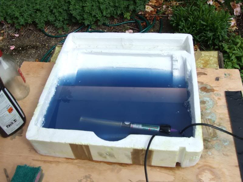
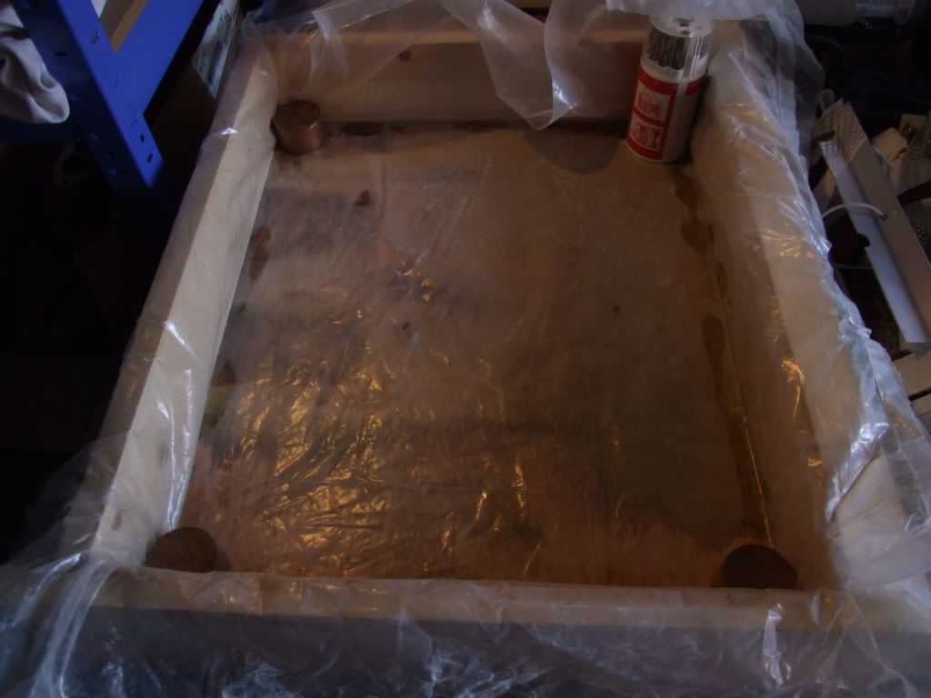
 , so it has an outer box lined with plastic sheet a mattress came in - now it's in the styrene tray to avoid cutting up the plastic lining:
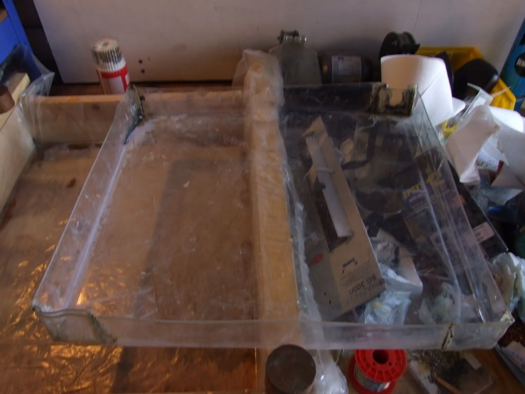
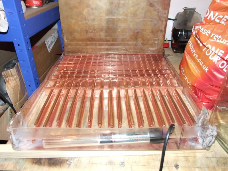
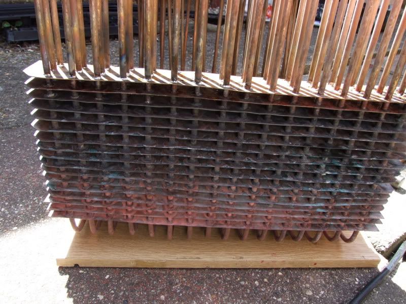
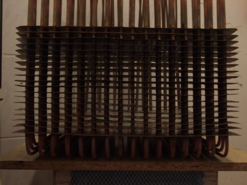
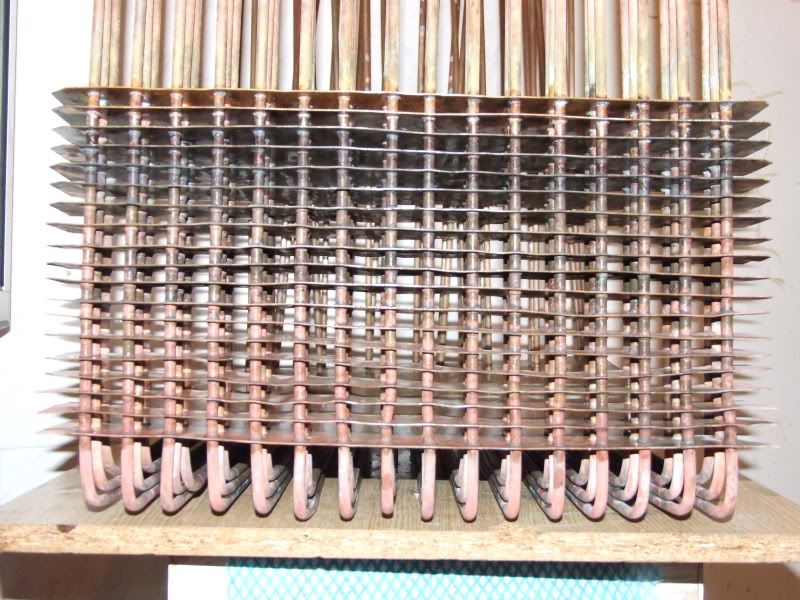
 it looks like a giant version of my cpu cooler but in copper...