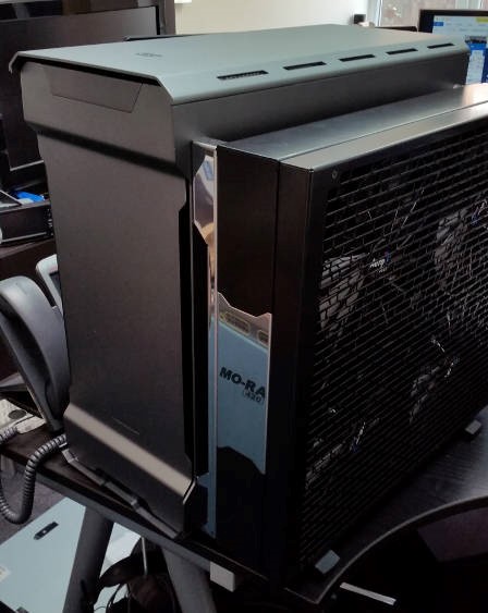
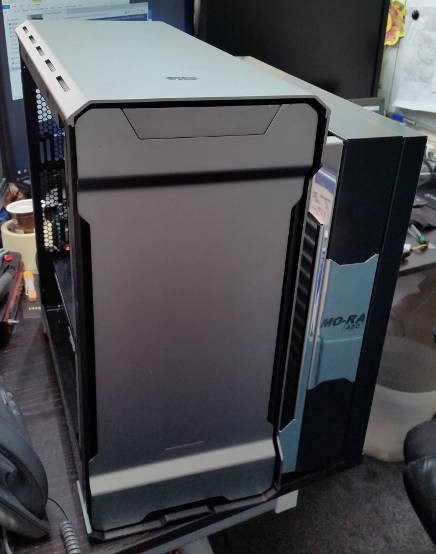
Project: Silent Overkill

Got some more Barrow fittings today (thanks Mark!) and have started building chains of fittings to get round the really tight spaces.

Just picked up the extra Tygon tubing (seriously, you go out for just one hour the whole day!) and also the Dr Drop leak tester. It leaked. Not kidding.
Had to partially immerse it in water to find out that the leak was coming from where the gauge screws onto the body. Luckily tightening it with a spanner seems to have done the trick. Leaving it under pressure for a while to make sure I don't have to resort to PTFE tape on the threads too. :rolleyes:

Lol the irony about the leak tester. Would like to see how you got around the tight bends, might help me decide too.

This build looks great! I thought about delidding my X58 Xeon but they are soldered on instead of glued so bad idea lol.
 
Last edited:
No problem. Bad quality pictures coming up :D

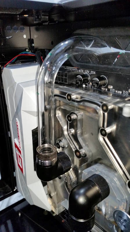
CPU up and over the top so it can join with the rad. It's ok, I know the collar is missing :D


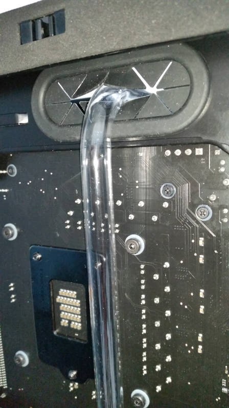
...and down the back. Have yet to pressure test the acrylic - bit dubious of it since I over-cooked it a bit. Not an easy bend though as it has to be accurate both in position and curve but is too close to the first 90 degree bend to use a mandrel.

The hinge part is still in progress but it'll either be soft tube joined on with a fuel clip, fittings across and then soft tube back up again to the rad fitting. The down and up loop gives it the flex so you can open the door without disconnecting. Other option is to cut the acrylic after the first 90 bend, EK-HDC fitting > barrow 90 degree female to female non-rotary > 10mm extender to clear the motherboard tray > EK-ACF connector and then as above. It removes the second acrylic bend but does put an acrylic compression fitting right above the top of the motherboard.


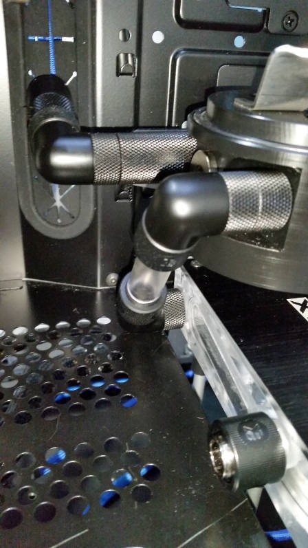
Res to pump fittings: Res > Barrow 10mm extender (to clear res) > Barrow 90 rotary > EK-ACF > soft tube > EK-ACF > Barrow 90 rotary > Pump


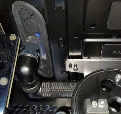
Res to back of case fittings: Barrow 7.5mm extender > Barrow 30mm extender > Barrow 90 rotary > EK 8mm extender > Barrow 90 rotary > EK-ACF > soft tubing to EK-ACF and Barrow 45 degree on flow meter.

Going to swap the EK extender for a Barrow of either 7.5mm or 10mm whichever fits better. Also going to try swapping the 30+7.5mm extender for a 40mm to cut out one fitting - depends if there's enough adjustment in the res mounting.

I've rotated it so you can see the fittings. Normally the EK-ACF sits in the rubber grommet so that it's pointing about 45 degrees downwards. May end up more towards straight down if the 10mm extender fits.


A lot of this isn't particularly aesthetically pleasing - you can see why I decided that most of it would have to be cut out of acrylic block work! It's a necessary stepping-stone to give me more of an idea of spacing, dimensions and any problems.....and I'll be able to get my gaming rig back up and running too :D
 
Er, slight change of plans!

Took some 13/10 acrylic tube, cut to the same length as the reservoir's central tube and threaded both ends to G1/4. Wasn't sure whether this would work as it seems to need to be tightened up quite a lot before it will hold the 0.5 bar of pressure from the Dr Drop. In a word: BANG!!
Turns out that the thread at the bottom was ok because the force was spread over the full 8mm length of it. At the top of the res, there's a chamber for the fountain effect. The bottom part of the thread is close to G1/4 and fits the steel central column. The top part is G1/4 (for a fitting) and there's a gap in between them so water can come up the central column and fountain out the multiple holes. This means that there's only a few mm of thread making contact at the top of the column; which is fine for steel but acrylic .....not so much. Explosive decompression and the o-ring whizzed off.

So, back to the steel central column and we'll have to scrap the different colour LED lighting the centre.....sorry OJ46!

It does also mean that I'm going to have to find out what thread the central column has. It's close to G1/4 as a G1/4 fitting will screw into the hole but the steel column won't screw into a G1/4 hole.

:eek: Hope I don't get that issue on my Aqualis! I'm using the center for fountain effect too and yeah the space between the shaft and the g1/4 inlet is very narrow
 
I don't think you should. It's only because I swapped out the nice strong steel with an exactly matching thread on the end for a nice brittle, hollow acrylic tube with a G1/4 thread which is slightly smaller. Turns out there was a reason it was designed as steel rather than acrylic....who'd have thought :rolleyes: :D

I can recommend the Dr Drop though. Mine, as said, was leaky but Aqua Computer were great and have just posted me another - and a replacement rubber seal for the fill-level sensor too. It was really useful to check I'd tightened up the res enough as at first, I hadn't and it let the air out like a whoopy cushion. Bit tighter and it was fine unless I pushed on the res (mine's the really tall 880 version) at which point it gave at higher pressures (over about 0.3 bar). Bit tighter and it stays sealed with the full 0.5 bar of test pressure....which is good to know before I fill it! ...and also means I don't have to drain litres of fluid to fix it.
 
So with the pressure testing looking good (I'll retest it once my non-leaky pressure tester arrives!) I've started working on finishing the loop and starting the electrics. I need at least some of the electrics in to run the pumps when I fill and so on.

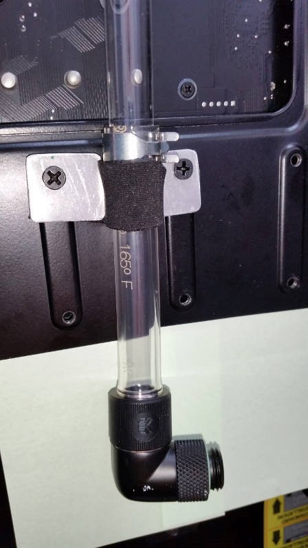
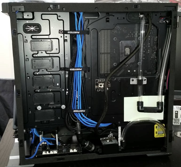
I've constructed a restraint from neoprene (meh, it was sitting on my desk being an ineffectual bag thing) and some ali sheet. The idea is so that when I open the rear panel, the stuff that's supposed to flex will and the stuff that isn't (the acrylic that goes up and over and connects directly to the CPU) will stay put. May eventually paint the ali black but depends on the superfluousness of my sanity.

Piping-wise, that's 12/10 acrylic coming down and then 13/10 Tygon soft tubing (actually 12.7,9.5mm as it's 3/8" ID). Connecting the two is a 14-16mm fuel hose clamp. Why? I just plain don't have the room for an EK-HDC back to back with an EK-ACF - the door wouldn't shut. I jjust about get away with it further down with the 'hinge' but it fits exactly and the flex lets it line up. I just couldn't get that sort of accuracy bending the acrylic to be sure it would sit exactly flat.


The post-it note is just to stop it scratching as it dangles about unconnected. Could even go as far as some black duct tape as a permanent solution! :D

So that back is beginning to take shape. I've got the Aquaero mounted. The mounting holes lined up exactly thanks to my template....it just would have been nice if I'd ensure they were parallel to the part of the case that's relevant. One end is about 3mm closer to the edge than the other at the moment. I may have to turn the holes into slots and move that out but I'll see how it goes - it's the cable management that will dictate it.

Flow sensor is mounted and I've allowed 10mm extra length on the off-chance I ever need to change PSU. There's now a filter attached to the flow sensor but this is intended to be a temporary measure until the acrylic is done.


You might just be able to see the Farbwerk behind the Aquaero. That's next to be mounted....while there's drilling being done :D
 
Managed to get a sleeveless paracord EPS extension done today. Will try to get some pics up tomorrow. It looks pretty good for a first go but suffice it to say that I now hate crimpers, paracord, stealth combs and heat guns! ;-)

On a serious note, I think my crimper (I have a Weirieli SN-28B) may be naff....although it's perfectly possible I'm just blaming my tools! Mine seem to smush rather than crimp and the legs for the insulation get pushed backwards and end up sticking out the back like wings. Has anyone got any recommendations for decent crimper that don't cost a ridiculous amount?
 
Has anyone got any recommendations for decent crimper that don't cost a ridiculous amount?

E22 and Shakmods. Both look like the MDPC-X crimper, and E22 say that their ones have been individually dialed in for best performance.

£35 plus P+P

davido_labido covered the E22 tools in a video a while back and he loves them.
 
Well why didn't they say on the item description "As loved by davido_labido"?! I'd have known they were good then :D
Thanks for that I'll give some a try. If nothing else, I can find out its my skill lacking and not the tools!
 
Well why didn't they say on the item description "As loved by davido_labido"?! I'd have known they were good then :D

I'll give Nate and Vic at E22 a shout then :p

Or do a limited davido_labido edition in orange and doesn't actually work until the last minute :p :p (I'm joking dude if you're reading ;) ).
 
I use the Weirieli crimpers and haven't had any problems once I worked out the technique.

What's the trick? I can get it to work but it's not doing the insulation crimp very well, tends to bend the pin and leaves wings sticking out the back of the pin rather than folding them round the top of the wire. It fits in a housing but its a real pain to get them through the stealth combs I was using - these are the ones you have to thread onto the wire rather than clip on. Pics to follow.
 
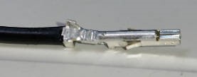
Ok, pics as promised. This is what I mean by smushed with wings sticking out the back. I can improved it slightly by trimming the wings back before crimping but it's still smushed rather than properly crimped. Molex power pins are even more deformed.


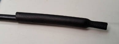
I hadn't ordered one of those paracord sleeve threading tools as I'd not watched the video at that point that showed you put the pin on first and then the sleeve afterwards. This is what I came up with. It's just a short length of 3.5mm heatshrink with one end shrunk. Slides over the pin nicely shielding the spikey wings from snagging the inside of the paracord and the pointy end just works like a needle to slide through. Reusable and cost me maybe a penny :D


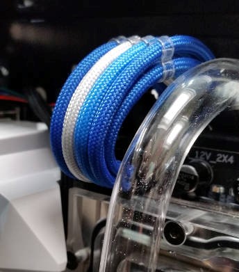
This is the result. What do you think?

 
Finally got the rad on and the hinge 'system' fully tested. Have opened and closed it a few times with 0.5 bar of pressure in it and so far it's fine :D


Still some more work to do with electrics but I'm waiting for the new crimpers before I carry on with that. For now, I think I might start getting it wet :D
 
You and me both!

Still a fair way to go though. I still need to sort out three 4-pin Aquabus cables, Aquaero to motherboard USB, two PCI-E, ATX cable and a bunch of RGB LEDs.

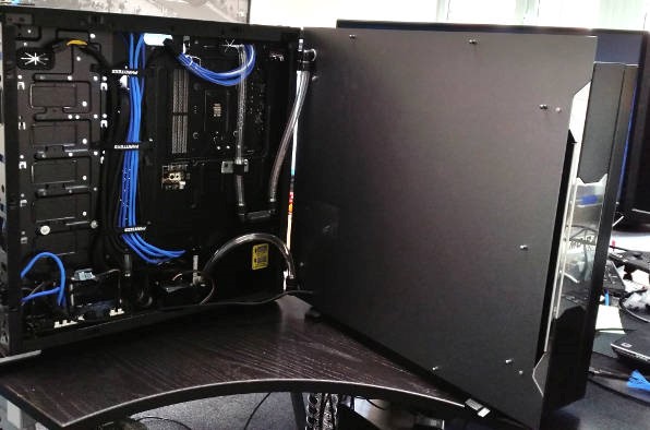
Anyway, OPEN is easy. It was getting it to close with water run between the motherboard tray and side panel that was the pain! Slapped some more panels on for an idea of external look when closed. Excuse the bad pics; light isn't fantastic in here for pics and also, I just couldn't back up any further....no more space!

All pics clickable for larger, grainier version - as always.


Aargh! Disaster! Turns out this project is being run by an idiot! :eek:

Just shy of 2 litres of coolant in so far so I start reprogramming the Aquaero so I can use it to spin the pumps to circulate the coolant round, top up repeat. Some sort of air-lock...which is odd, because not long before I'd been pleased that because the res was above the pump (unlike last build where it was about level with it but had tubing that dipped down then up) the coolant had already filled the pump so I shouldn't have this issue. Well, I wouldn't have had this issue if I'd not been stupid enough to connect the pumps backwards! [facepalm] :mad:

Now, how to drain the loop to swap the hoses around. A drain port you say? Yeah, that would have been a brilliant idea [facepalm]

Now where did I put my cluebat?!
 
Back
Top Bottom