Project: Silent Overkill

OJ46: Deliberately making something badly just doesn't sit right with me...even with the market economics behind it. Like you say, it'll be interesting if AMD can give them some competition again.

BornEvil: Good to know. I'd heard about 10C. My CPU max core temp hits the high 70's when playing a game that uses the CPU so a 10C drop would be nice. 8Pack commented in another thread that it's probably my board supplying too much voltage when the CPU is on turbo (4.4GHz all cores) so I probably need to sort that out but starting off by dropping the temp isn't going to be a bad thing! :D

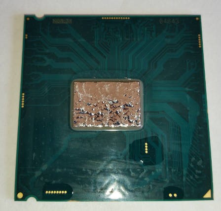
Progress pictures :D Cleaned up the existing gunk and applied some Cool Laboratories Liquid Ultra (CLU)
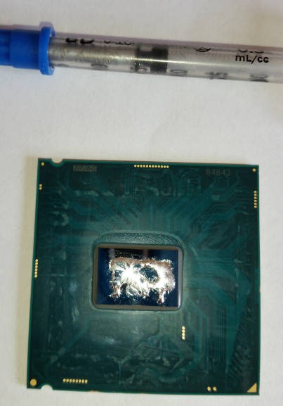


Spread it out with the supplied brush. Was a bit worried it seems a little lumpy but it seems to be the case in their instruction videos as far as I can work out. Assume it'll be fine when squashed and/or heated. Also applied a bit of clear nail varnish (who said wives weren't useful! ;) ) over the uninsulated terminals in case the CLU spreads. Just because you're paranoid.... :D


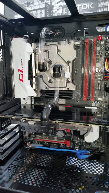
....and assembled. The black wires are temp sensors I stuck on the bottom of the M.2 SSDs to keep an eye on them. As far as I can tell, once you've stuck them in RAID 0, there's no way of accessing that data. Temp from the top of the chip would be more accurate than the bottom of the PCB but I wasn't going to be sandwiching the probe between the chip and the heatsink.
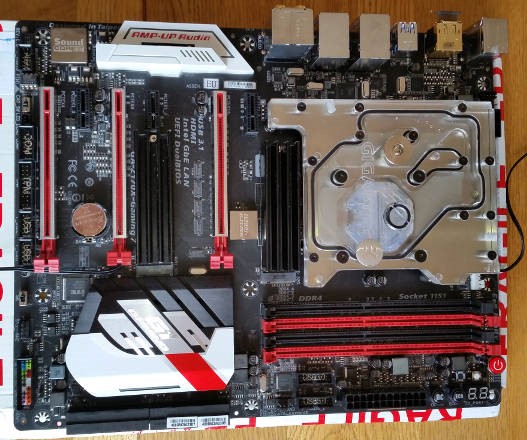


Hope to find out whether it lives later today :D
 
*drumroll* really want to see your temps, really don't have the cojones to delid my 6700K

Haha this is definitely tempting me to remove the lid on the next one and hey, if it all goes **** up I'll just steal the CPU out of the current gaming rig... Then probably attempt it again and break that one as well :p

That's definitely some strange looking thermal paste you've got there though. Still, could be bright pink with googly eyes so long as it works! :D
 
So I've got a functional system now, right? Er, no....but you're not that surprised are you?! :D
Apart from work, I hit a couple of stumbling blocks. Just before I mounted the motherboard it occurred to me that I wouldn't be able to insert the LED on the IO panel side of the monoblock once the IO shield was screwed on and that I wouldn't be able to screw that on after mounting the motherboard. I had to make up an RGB LED on an arbitrary length of cable and sleeve it. I also had to assemble the two pumps and sleeve the two cables - I tried not to but I had to cut the molex off and put a 4-pin on anyway...so it would have been rude not to! :D I can always shorten them once I know final lengths.

Pump and LED cables each have four wires. Technically you can get four wires through a paracord sleeve. Should you? Well, only if you can answer "Hell no!" to the question "Do I value my sanity?"!

So motherboard is in and pump is ready. More progress tomorrow afternoon.
 
Progress? Er, some. It's been one of those days where every time you try to get something done someone interrupts. I've got a bend done from cpu to gpu and most of one from cpu up and over the motherboard tray. Must have got through half my tubing and I'm not sure I'm happy with the bends I've got to be honest. Had to make up a bending guide for the up-and-over because the 2nd bend was too close to the first one. Will try to get some pictures up tomorrow.
 
Oh, on a comedy note. I discovered what happens when you blow the acrylic dust out of a tube bent to 180 degrees. Who'd have thought?! :rolleyes: *blink* *blink*
 
great board, but had issues with dual bios, and when you update the bios it only did one. In the end I just disabled dual and left it running with one. stopped the booting to default speeds etc.
 
Subbed! Might give this delidding lark a go.

Maybe wait until I confirm (or not!) that it still works before you take this as a good reference! :D I think it should as there's no damage been done.

great board, but had issues with dual bios, and when you update the bios it only did one. In the end I just disabled dual and left it running with one. stopped the booting to default speeds etc.

I didn't have many issues with mine but I did have with the identical board I used to build for a friend. I think that once you get a boot failure it flips to the other bios which then defaults and then you get stuck in a loop. A slightly older bios worked best for me - think it f6 but I can dig it out if you need it. Had issues with RAID 0'd M.2's otherwise. Like you I stuck his board in single bios mode but mine's still in dual for the minute.
 
Cheers. It's the holes I've drilled in it that really make it ;) I like the clear ones as you can see if/when it's getting clogged up with any gunk....although hopefully the filter going in should take care of that.
 
Just a mini update with hopefully more to come today.
I got the GPU to CPU hardline bent yesterday after a few false starts. Also got the CPU up-and-over bent after some misses, some fails, some snapping and some swearing :D


Looking to do most of the rest in soft tubing at the moment (unless I run out!) simply because it's only temporary so no point in making it harder than it needs be!

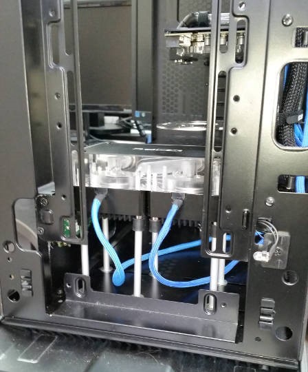
Res mount is mounted and I managed to find some existing holes - again, it's temporary so I don't want to be drilling more. Have got the res reassembled too - just need to leak test it before it goes in as I took apart the level sensor end I don't want 880ml of coolant in a leaky res! :eek:
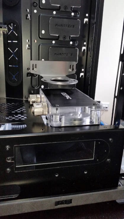
Pump is assembled, sleeved and in place. Cables are too long at the moment but can be shortened Once I've got final positions for everything.


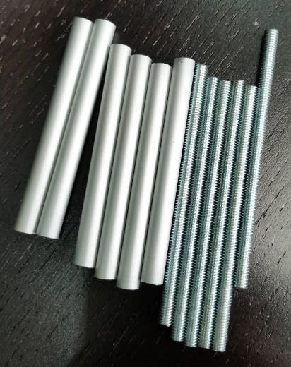
To get the pump at that height, I needed some legs. Some 4mm threaded rod and some 6mm aluminium tubing from B&Q plus a hacksaw equals legs :D Remembering the old adage: measure twice, cut once, swear once and drive to ScrewFix for additional washers so the inlet fitting doesn't hit the PSU shroud :rolleyes:


...and mounted. Why six legs? Well, clearly six is better than four and I couldn't get the additional two in without drilling holes in the bottom that I don't need there long term.


Well, back to the grindstone. More later, wife permitting! :D
 
And it.....leaks! Bit of a leak round the bottom of the glass that was sorted by tightening it up but also a weeping round the level sensor. Hopefully a smear of LS-X should sort it out. Will find out when it sets.

First time I've ever leak tested something outside the case...looks like it was a good job I did!
 
Well over 12 hours later the LS-X hasn't set. I dunno, you have a tube lying in your water cooling box for just ten short years and what's in the bottom of the tube, after you've drilled through the solid stuff at the top, doesn't set! I demand my money back! ;) Well, off to buy another tube and then its wash, rinse, repeat.

Also found that I'm going to need more Tygon and some more fittings for the rather awkward angles so I'm not going to be able to complete the loop until that arrives :mad: Will try to post some progress of mounting the bottom half of the Aquaero and the flow meter in the meantime.
 
These look quite useful for leak testing the loop, could save a lot of money and hassle if there is a leak above an expensive component :)
 
Actually that's not a bad idea. Normally I go with the kitchen towel method but it might be reassuring to test my dodgy-looking up-and-over acrylic bend!
Might be able to work out a way of getting them to send a replacement rubber grommet thing for the res to sort it properly.
 
New tube seem a to have set better. My old tube I had to drill through the solid stuff about 3" to coax out some unset stuff. I'm guessing what I got hadn't set because it was never going to. Did seem to stop the leak ironically...but wasn't happy leaving it as mush.
Have ordered a Dr Drop (cheers for the suggestion OJ46), some more Tygon and enough fittings to (hopefully!) finish the loop and find out if the delidding worked!
 
Started thinking about wiring up the RGB LEDs this morning. It suddenly occurred to me that 4-pin RGB LEDs ,with their common pin, cannot be wired in series. This means I've either got to wire them all in parallel and provide each LED with three separate resistors (cannot share them as apparently you end up with very different brightnesses) or look at 6-pin RGB LEDS which can be wired in series (oh good, more tiny pins per LED :rolleyes:) Back to the drawing board on this one I think!
 
Looked into 6-pin RGB LEDs assuming they were just RGB with shared pins so that I could chain them together in series.....no. Turns out they're four-colour Red, Blue, Green, Blue with two common pins. So I'm stuck with 4-pin RGB LEDs wired in parallel with three resistors per LED. I was thinking that for the res, where there are eight LEDs planned and one in the centre, it may end up more workable to design a PCB and mount stuff through-hole.

Anyone got any experience of doing this or know who could etch a PCB if I could give them a plan of it?

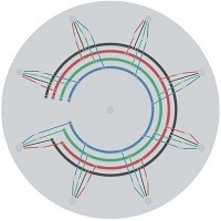
This is the kind of thing I'm thinking of. A circular PCB with the eight LEDs round the edge - the four holes are the mounting holes for the pins and the round bit just to show there's an LED there. Resistors are mounted through-hole which allows the connections to 'jump' over the intervening tracks. Central LED is planned to be a separate circuit so it can be a different colour - OJ46, this is your fault! :p


Just spotted that I need another set of holes; one for the LED pins to be soldered into and one for the resistors. You get the idea though.

Any comments, suggestions, dire warnings? Seriously, I'm going out on a limb here....trying to catch up with my sanity! ;)
 
Back
Top Bottom