build help

Soldato
Joined
14 Jul 2005
Posts
9,363
Location
Birmingham
Hi all,

Started building my new pc. Gonna use this thread for questions.

First one.

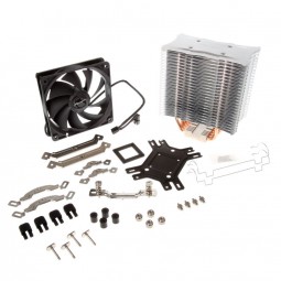
The CPU cooler backplate installation was quite fiddly, but Ive got it installed. There are four thumbscrews that hold the back plate in place along with 2 mounting bars at the front. How tight? Thumb tight or do I use a screwdriver to tighten them up more? I did it diagonally.

HS037AL_49243_285x255.jpg
 
Last edited:
Oh those, give them a quarter turn or maybe upto half a turn with a screwdriver after making them thumb tight.

You've put the rubber things on the tips and got the hole on the backplate where the screw thread pops out at the rear of the socket?
 
There was a square foam thing that went inbetween the backplate and the back of the motherboard, and there were four rubber 'feet' that went on the backplate lugs.

There were four threaded pins that went through the holes in the motherboard to the front and then a plastic spacer went on each of these pins, then the metal brackets and finally a thumbscrew on each corner.

Lol. I think I've done it right. The instructions were not massively clear.
 
The foam thing might be for LGA775 setups.

Check the manual.

The backplate has 3 holes in it, these correspond to the three screws poping out the rear of the socket.
 
Oh ****. There is a tiny little note attached to one of the diagrams saying the insulation washer is for LGA775. Its not at all clear as the section has all the socket types on it and the diagram shows the foam washer installed. The text doesn't say its only for 775 either.

I guess I need to dismantle it to remove it now. I can't leave it can I?
 
Its not going to cause any harm, but if its not letting the backplate sit properly (those rubber bits should be touching the PCB) then it needs to come off.
 
It sits much better now, not as fiddly to get the screws on so it must have been in the way.

If you take a look at my 1st pic above, those 2 metal mounting plates - the hole where the cooler strap mounts is directly over a couple of circuit board components. Do I need to orient those metal brackets inwards rather than outwards to avoid the screw being above the circuit board components?
 
You have them the way around the manual says to have them.

Do you think the cooler strap screw will hit this component when tightened down.?
 
I thought it might, but not to worry it doesn't.

Here is finished product. 1 pea sized amount of thermal paste not forgotten lol.

sdec7t.jpg


Think I'm done for tonight now, don't want to rush it.
 
Ram is in and fan is on. Fan right way around?

28svdjc.jpg


Question - what is this for? It came with the motherboard but manual doesn't seem to mention it.

303ifjd.jpg


And one more question.

The case (phantex p400) has the standoffs pre-installed. There are 9 in total, 3 top, 3 middle, 3 bottom. However the motherboard only appears to have 7 holes - 2 top, 3 middle and 2 bottom. It also seems that the middle row of 3 holes doesn't match the spacing of the 3 standoffs in the case.

Any clues on what to do here appreciated.
 
Last edited:
Question - what is this for? It came with the motherboard but manual doesn't seem to mention it.

303ifjd.jpg

It's a custom connector that makes it easier to connect all the little case leads to the motherboard. There's a collection of thin leads inside the case which should be marked HDD LED, PWR LED, RESET and so on. These need to connect to a block of little pins on the motherboard and this is usually really fiddly to do (easily my least favourite part of any build).

That connector helps the task because you first put the fiddly leads into the connector, then plug the connector into the motherboard.

If you notice, that package in your photo is sub-titled "Installation Guide" which will help explain what plugs in where.

Regarding the standoffs, these should unscrew so you can remove any standoffs that you don't need. Looking at the manual for your case they are listed as separate components, so should be detachable. If the middle ones don't line up, you might find the baseplate in the case has extras threaded holes where you can move the standoffs to suit. If not, just remove any that don't line up. Looking at a photo of your motherboard it's the one adjacent to the red DIMM slot that looks problematic. As long as the other two line up you're fine.
 
Last edited:
Thanks. Yes only 6 standoffs used. The board isnt wide enough to use the final 3rd set of standoffs. There is no standoff position in the case to use that 3rd hole on the motherboard near the red ram slot. Bit strange as board is atx i expected to use all 9 standoffs.

Think I'm done apart from a few cable ties:

35l57yw.jpg


Not switched it on yet as got to go to work.
 
Last edited:
The dimensions of the Gigabyte K3 board is a bit smaller. It measures 305 x 231 whereas the usual size is 305 x 244 so that will be why it isn't using the outer 3 holes.
 
I would have preferred that the right hand side of the board was properly supported in the case really. But i guess its ok now its installed.

Yes, but when you stand the case up the motherboard is on its side. So, the weight distribution probably isn't what you expect anyway. As long as it's secure you'll be fine.
 
Back
Top Bottom