My desk project

Soldato
Joined
18 Oct 2002
Posts
8,016
Hi all,

First off, there's some amazing desk projects going on in this section - this won't be one of those!!

First, a little background (all good stories have a start, and it's a way to add a few photos to give you something to look at!)

About 18 months ago, I got given by a work colleague an old full tower case, because I'd moved my main PC components & watercooling setup out of an HTPC case, and left the HTPC to HTPC duties.

It was beige, oh so very beige!

IMG_0448.jpg


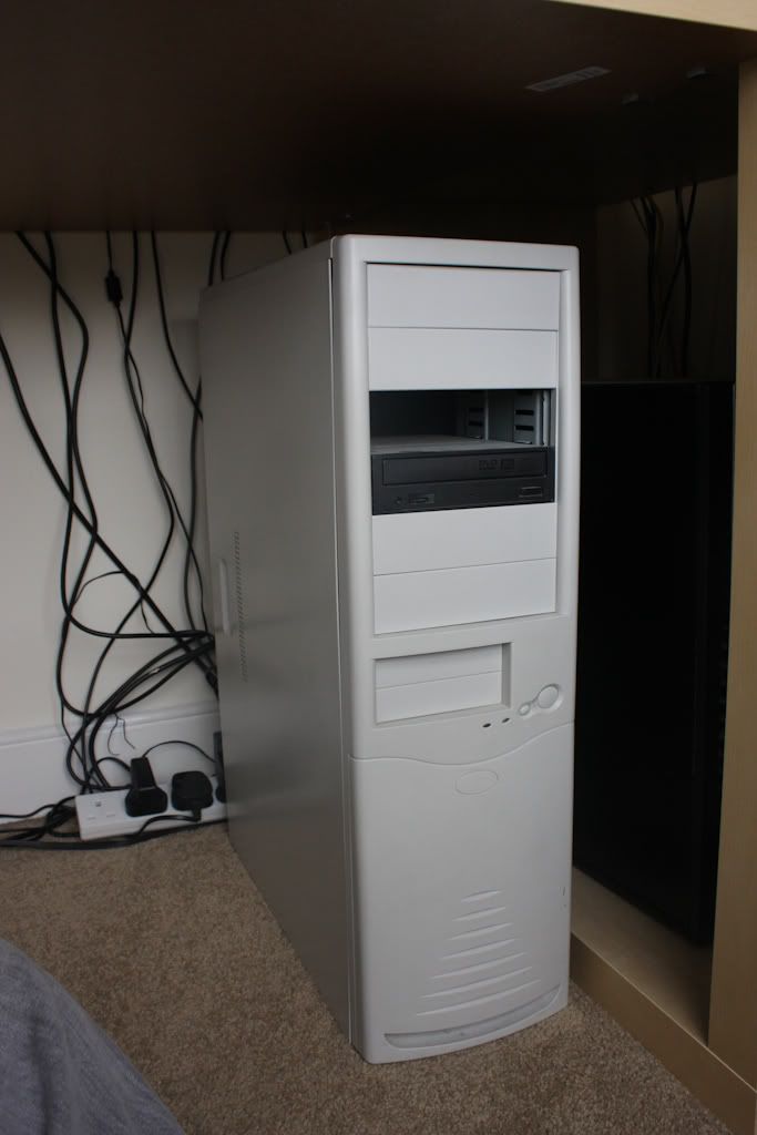
Even in 2010 when I got this, beige was bad! But - I had been given it for free, and I needed to then just do my best with it, and get my PC up and running again.

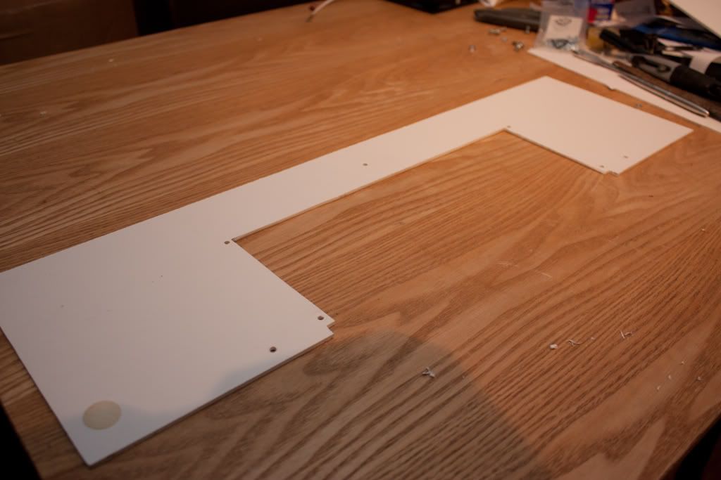
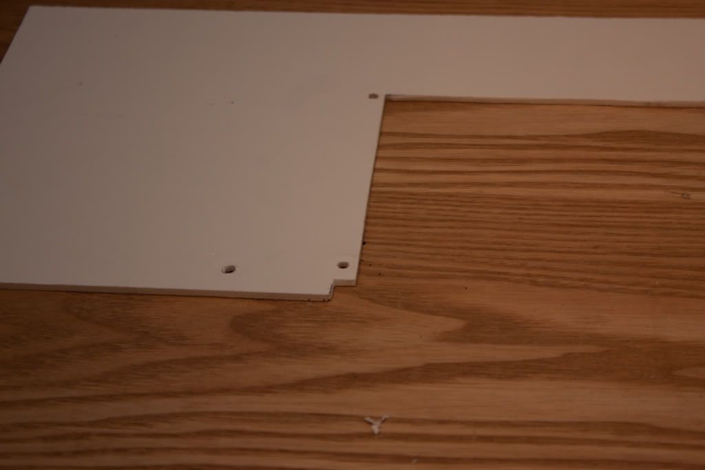
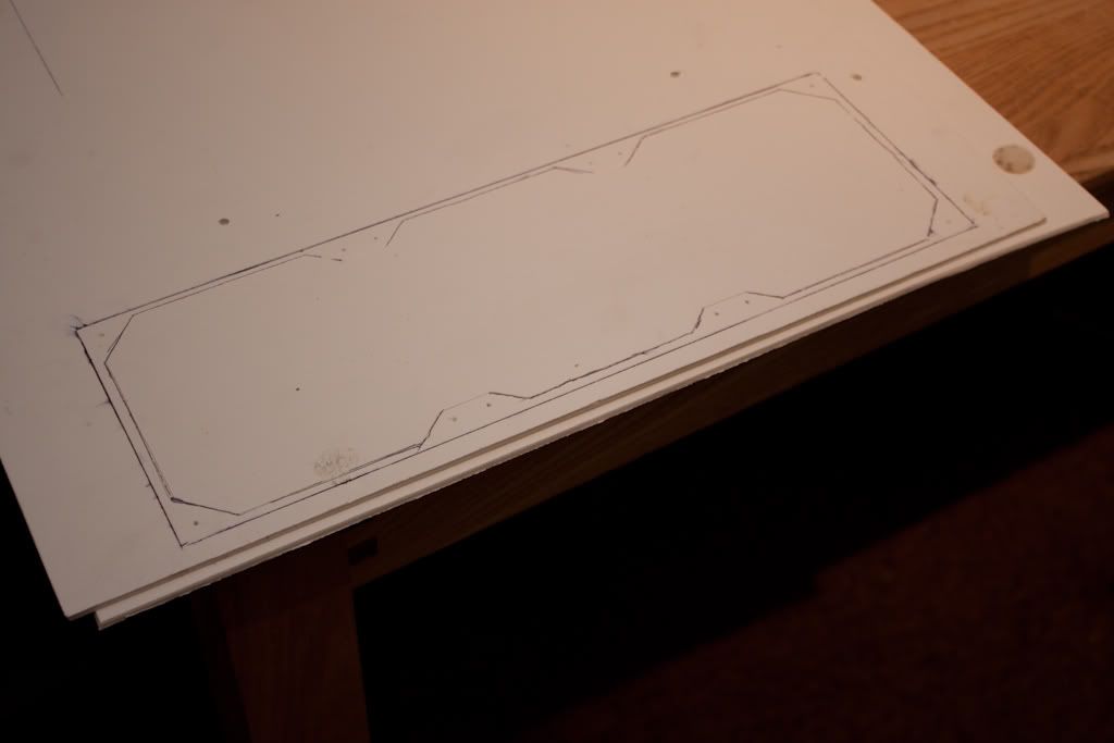
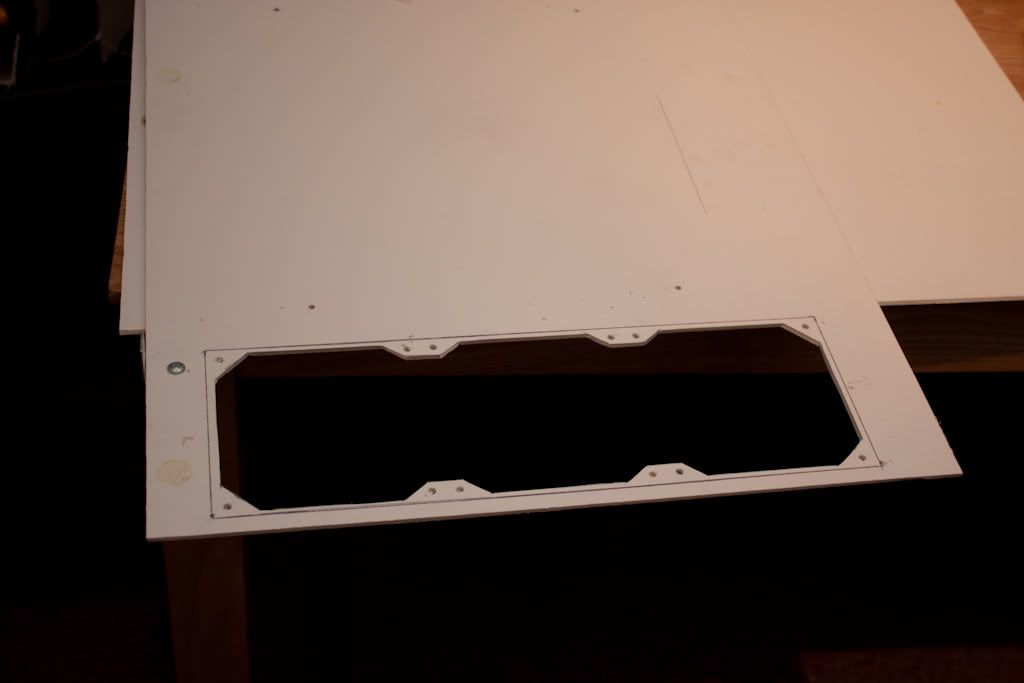
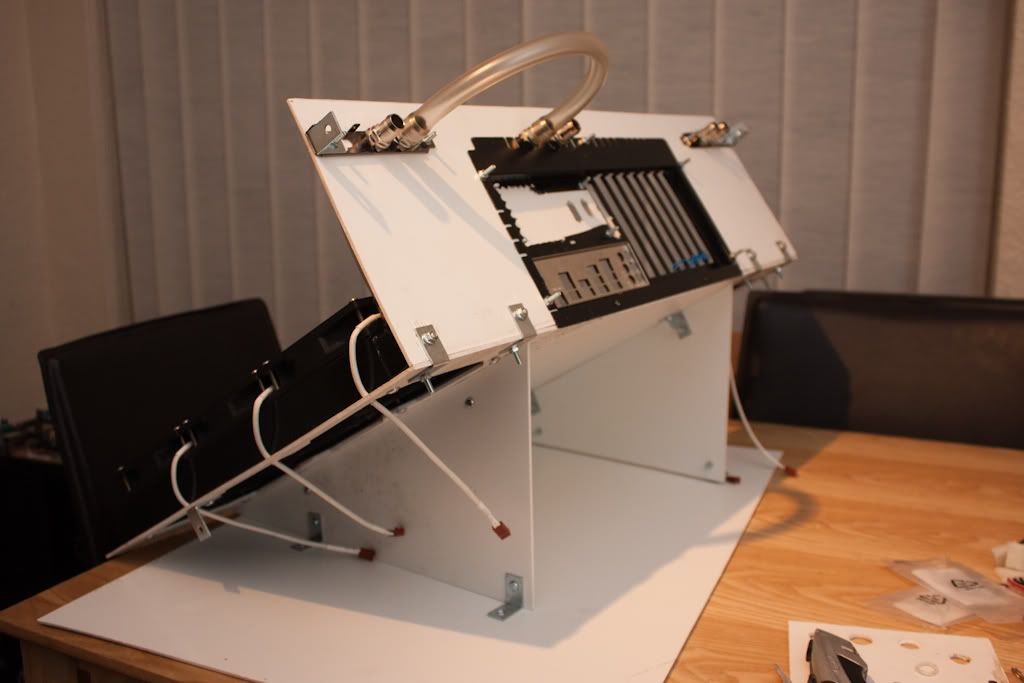
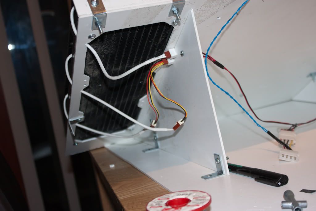
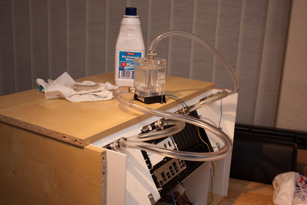
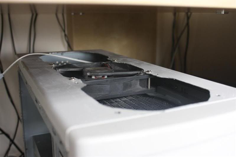
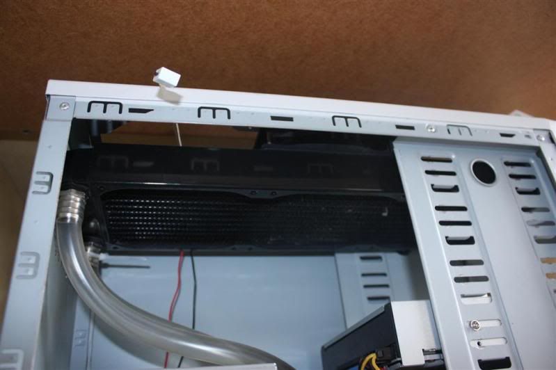
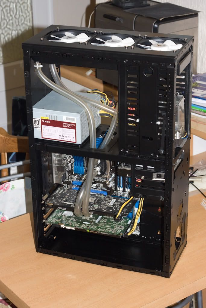
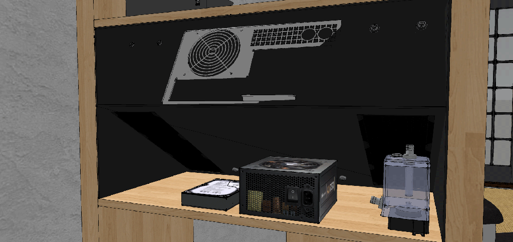
Armed with not much more than a drill, a hacksaw and a file, I went to work, and begun by marking and cutting out a hole for my XSPC RS360 radiator.

Computer03.jpg


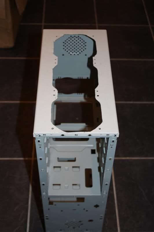
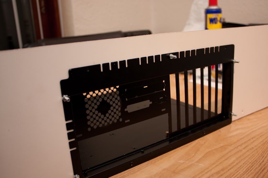
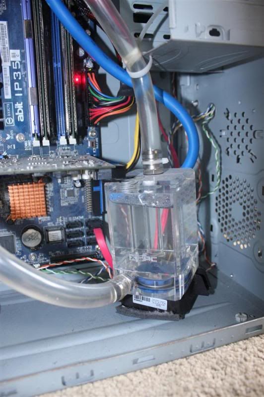
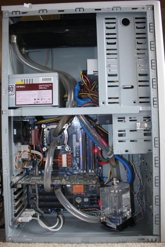
And with only a single fan, the radiator went in, as did the rest of the components - at the time an Abit IP35, Q6600, 8800GT.

Computer09.jpg

Computer06.jpg

Computer07.jpg

Computer05.jpg


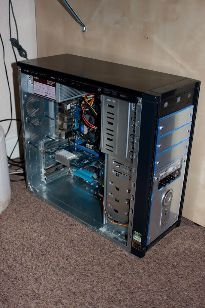
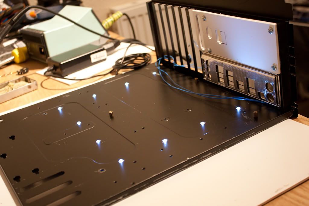
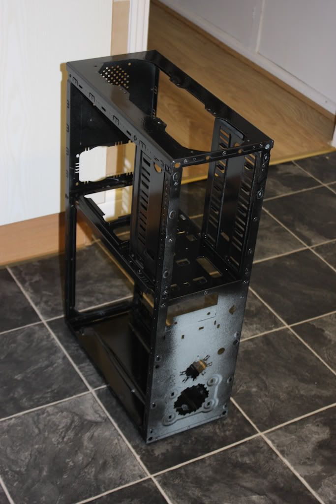
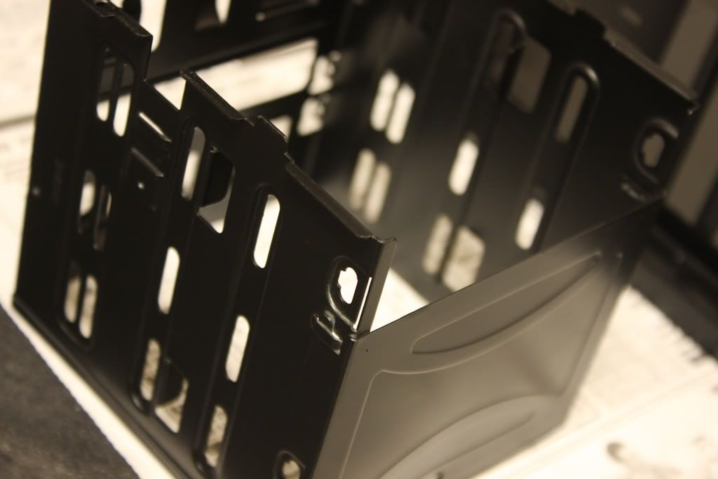
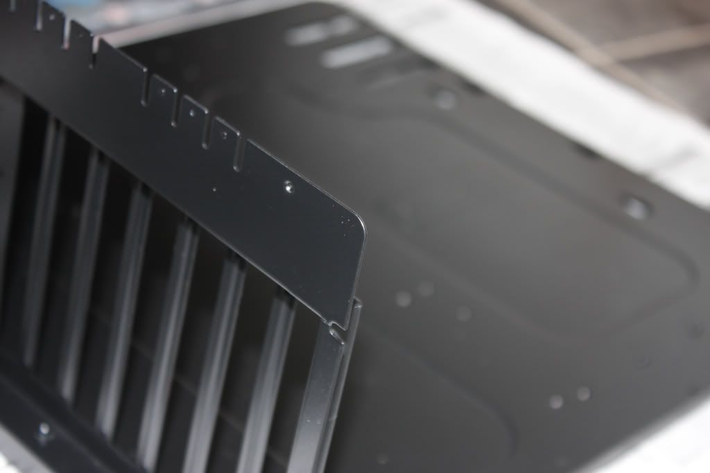
And that's how it stayed for a year or so, until one day I got annoyed with the beige, and wanted it black, instead. So, out came all of the components, and armed with a tin of black paint, I got to work again.

IMG_2109.jpg

IMG_2114.jpg

IMG_2116.jpg


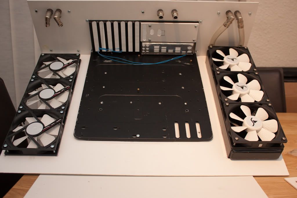
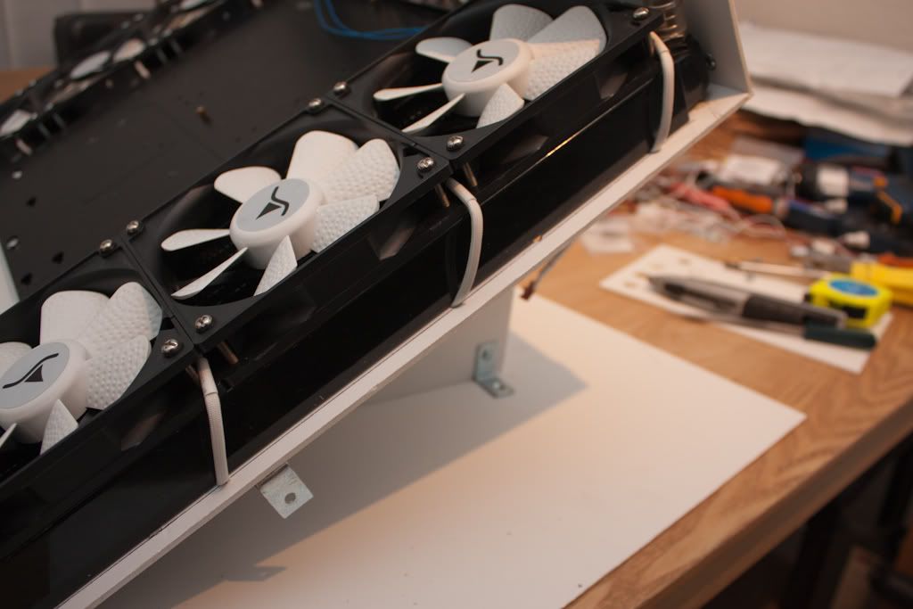
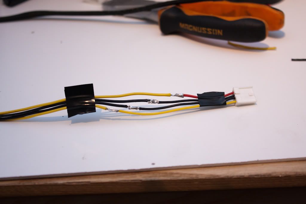
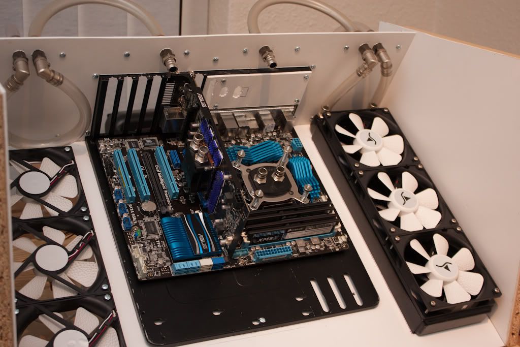
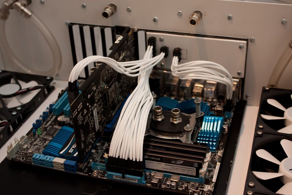
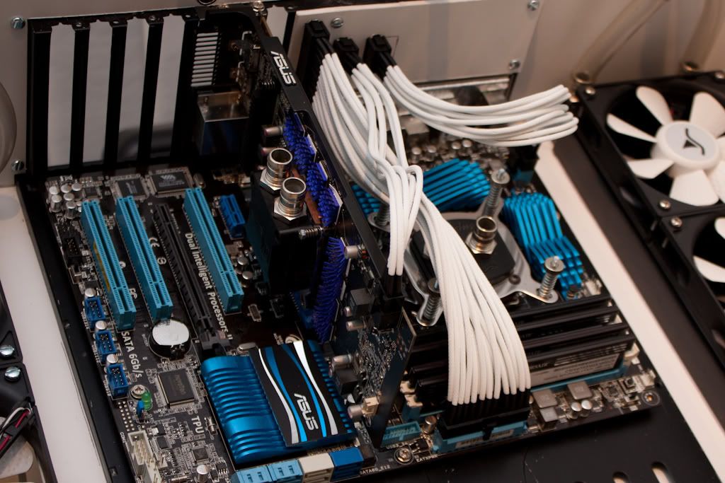
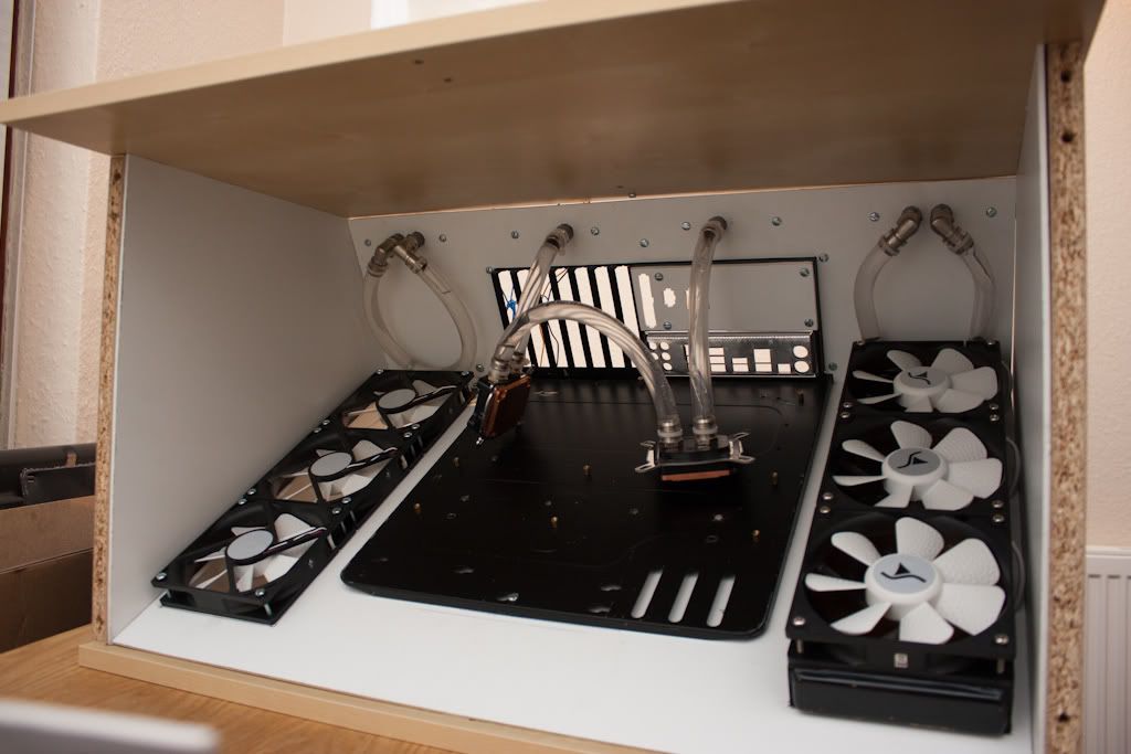
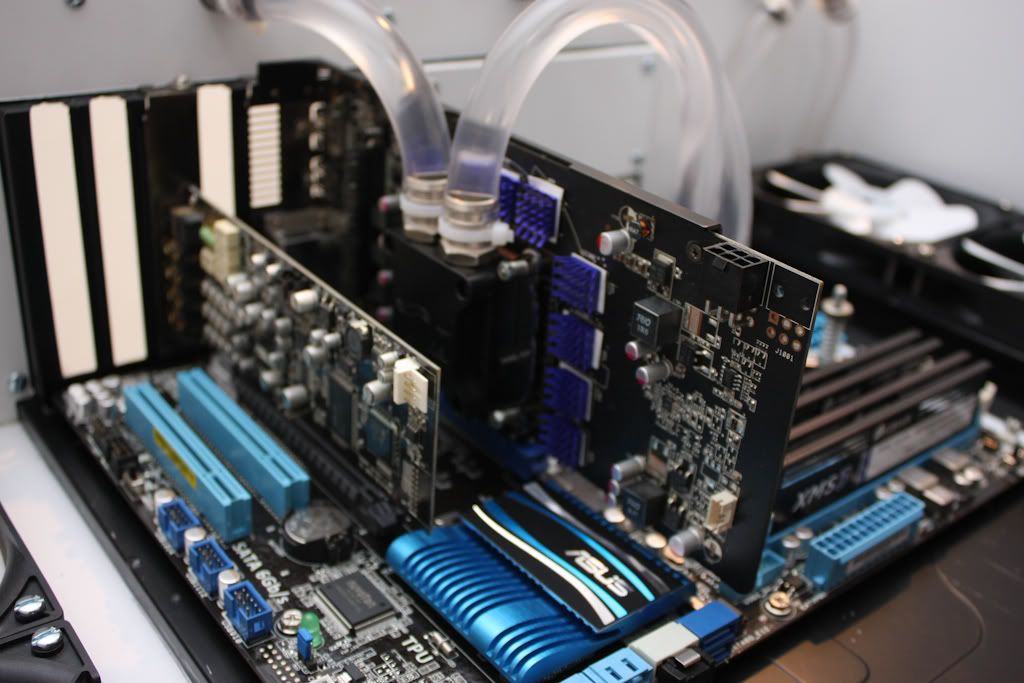
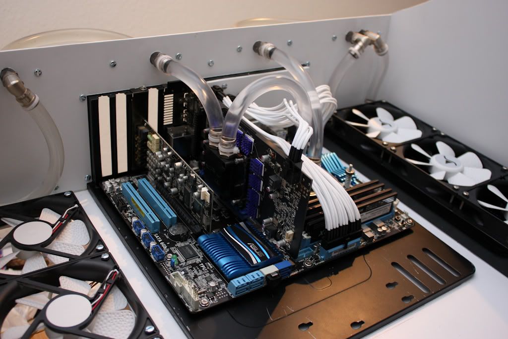
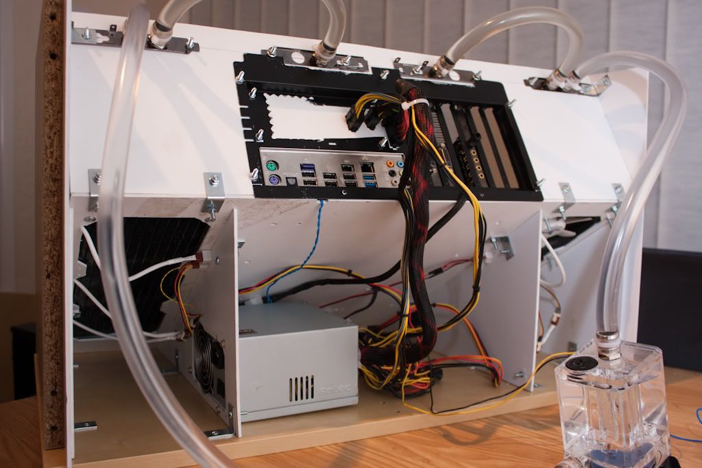
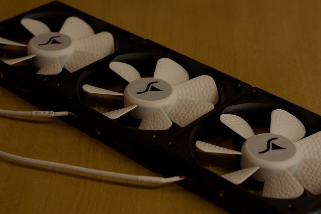
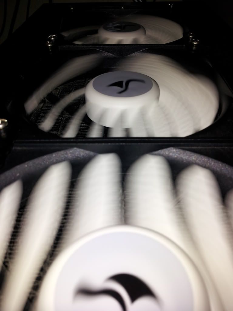
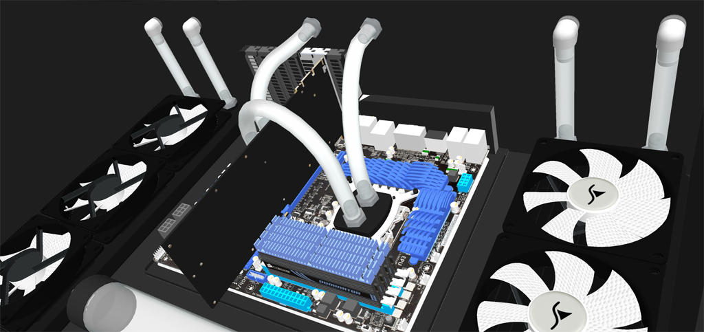
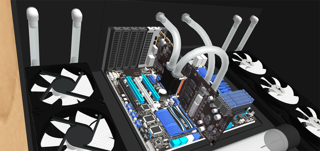
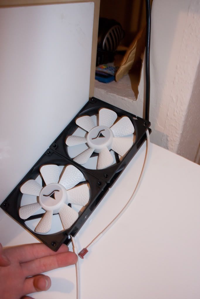
I also purchased some nice new fans - Sharkoon Silent Eagle 1000, and with those, and my other new bits - Asus P8P67, i5-2500k, HD6850, I began to reassemble.

IMG_2126.jpg

IMG_2128.jpg

IMG_2146.jpg

IMG_2140.jpg

IMG_2150.jpg

20120201_230638.jpg


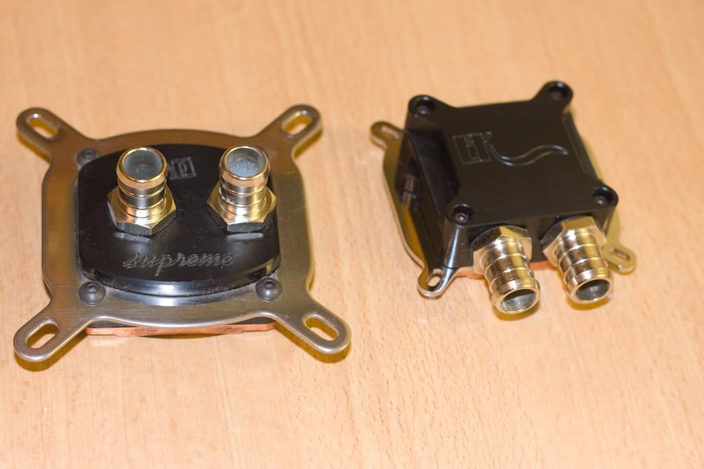
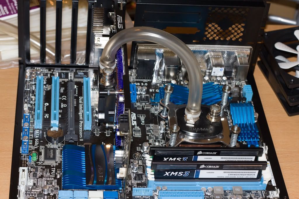
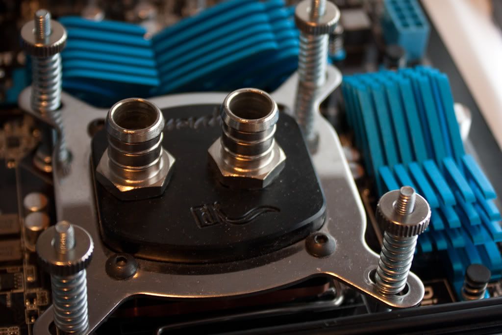
A little while later, I added another fan to the front, to blow over the hard drives and the memory on the graphics card - having a chip-only block and not a full-cover block, meant that I needed airflow over the GPU memory.

20120201_230539.jpg
 
Soldato
OP
Joined
18 Oct 2002
Posts
8,016
However, I've now decided that I want to change things around a bit. I've yet to see any cases that really grab my attention, and due to the desk that I've got (Ikea Expedit bookcase with the desk extension) and the orientation, there's few cases that will both fit in the gap I've got, and allow me to view the watercooling stuff.

Therefore, I've decided to design and make something that will fit the space, and show off my PC.

So - I introduce to you, my desk design, modelling courtesy of Google SketchUp - the 3D warehouse is great and you can find almost anything!!

desk-final-2.png

desk-final-1.png

desk-final-3.png

desk-final-4.png

desk-final-5.png


I have a home server sat on the bottom shelf, which runs mostly headless.

My plan is to have a nice sheet of either clear or tinted perspex on the front, and have the back part mostly open for the mess of cables - it won't be seen given the placement of my desk.

I may use something like the Bitfenix braided extension cables for the connectors - my theme ideas at the moment is black/white (it would have been a pain to model those - you can probably get the idea!)

I've modelled 2 radiators for symmetry - the second may not come just yet, but the 6 fans will definitely be there, so that there's a nice flow of air going over the motherboard and other components


Thoughts, comments, suggestions, improvements - all welcome :)
 
Soldato
OP
Joined
18 Oct 2002
Posts
8,016
I managed to pick up some old advertising boards from work, which are some ~3mm thick white plastic, which should be quite easy to work with - at the very least they'll be good enough to mock it up in something real, in case I decide I need some other material.

I started off by grabbing a piece, then measuring out for the angled base by using one of the original shelves from the shelving unit.

IMG_3641.jpg

IMG_3643.jpg


This stuff is really easy to chop up - something large and straight, such as a spirit level, and a sharp Stanley knife, and it goes through like a hot knife through butter!

IMG_3649.jpg


A quick calculation using an online calculator, and a left-over bit was chopped into a pair of triangles with one 30 degree corner to give some basic support at the right angle for the base part.

IMG_3646.jpg

IMG_3647.jpg


(I've not actually put them in the right positions yet, but the general idea is there!)

I think I'll be needing to get some right-angled brackets to start to secure some of this together - some careful planning and I should be able to get any screws that need to go through anything out of sight enough and behind other stuff, like the motherboard tray.
 
Soldato
OP
Joined
18 Oct 2002
Posts
8,016
So, I've cracked on again with this tonight.

First off I grabbed some power tools to begin some assembly of some bits. And of course - you can't work without a cup of tea, either!

IMG_3651.jpg


When I built the shelving unit, I was left over with 2 large shelves, and 4 of the dividers which sit upright. My plan is to use the 2 large shelves and 2 of the dividers to make a box frame which will be mostly solid and won't move (much) - but will still allow me to slide the whole unit out should I need to do any maintenance on the computer.

The dividers, however, wouldn't have given me enough space with them the "correct" way round, so I've now rotated them by 90 degrees, to give a little more height.

Also, because I want the insides black (for now!), I've cut out a piece of the plastic sheet to sit over the face of it, and one of the triangle pieces to give a guide for the angled "base" bit to be supported on.

IMG_3653.jpg


I've used the right-angled brackets as spacers so that the upright bits aren't tight against the inside faces of the shelving unit, just to give myself a little bit of "wriggle room" when sliding it in and out.


I then cut out another 2 of these triangles, so that I can have one either side, and two more further in-board to provide plenty of support to stop the angled "base" from flexing and getting out of shape.

IMG_3652.jpg


Mirroring to the other side, I placed the angled base on for a trial fit.

IMG_3654.jpg


I then decided to see how it would look using a couple of the extra Sharkoon Silent Eagle fans I'd purchased from the MM, positioning them so that they'll sit in roughly the right place once the depth of the radiator is taken into account, it seems as though I'm a little short on the depth of the bits I've cut out so far!

IMG_3656.jpg


And that doesn't take into account the space needed for the end tank on that end of the radiator which has the barbs in!


However - this isn't a huge problem - the bit that's currently at an angle will be just the right size for the roof now, and it seems as though the triangles are long enough, and I'll need to re-do the side bits - despite my best efforts at modelling it accurately in SketchUp - there's no substitution for making it for real and seeing whether it works! (And I've got plenty of those white plastic boards to mess with!)
 
Last edited:
Soldato
OP
Joined
18 Oct 2002
Posts
8,016
Measure twice cut once :p

Its getting there, will just take time and patience. Keep going :)

Where is the fun in that! ;)

None of the pieces will be wasted anyway, I'll find a use for them, if not on this then possibly my Ford Anglia project (details of which are in the Motors section!)
 
Soldato
OP
Joined
18 Oct 2002
Posts
8,016
I am, yeah.

I want the insides black, not white, not sure yet whether best would be to cover with vinyl wrap or paint.. I'm thinking that wrap would be better as I can cover some of the corners and edges.
 
Soldato
OP
Joined
18 Oct 2002
Posts
8,016
It does look similar - my colleague purchased it from the same place, around the same time too!

And yup, those are the Inspire 5300 speakers - absolutely brilliant, although in a house move I do seem to have lost at least 2 of the speakers, and the volume control is damaged... still not tempted to replace it with something newer, maybe just find some replacement bits!
 
Soldato
OP
Joined
18 Oct 2002
Posts
8,016
Been busy the last couple of nights on this, but keep forgetting to post progress updates!

The next task after my last update was to re-measure the angled base, and add the extra on so that the radiator and fans would actually fit!

Once I'd done that, I attached the two additional 30 degree triangles to the underneath of the base, and had a trial fitment.

IMG_3678.jpg

IMG_3680.jpg


Before I could move onto the next step, I needed to strip my current case down, and remove the motherboard tray. Therefore, I needed to re-home my PC temporarily, so I borrowed an old case from a friend, and transplanted my stuff - and as fitting the standard cooler back to my 6850 would have been more hassle, I have thrown in a 7300GT to give me some form of graphics!

IMG_3711.jpg


With the motherboard tray free, I could see how much space I'd have (as we've seen before, even measuring everything in SketchUp it wasn't quite right!)

IMG_3685.jpg


Looks like I'm going to be good there for putting the roof piece on :)


I then began to make up the piece to go at the back. I decided to make it the same shape as the original case would have been, so that I can attach the motherboard tray using the same mounting holes as on the original case.

IMG_3703.jpg

IMG_3705.jpg


And then affixed the motherboard tray to it.

IMG_3701.jpg

IMG_3702.jpg


Next, using a template I found on the internet for marking up a 360 radiator, I marked, and cut/drilled in the appropriate places.

IMG_3695.jpg

IMG_3694.jpg


Repeated on the other side, I then put these bits together.

IMG_3700.jpg

IMG_3712.jpg

IMG_3713.jpg


And, of course, tested it in-situ.

IMG_3714.jpg

IMG_3715.jpg


Next on the list is to re-do those side bits to fill in those little gaps in the corners - that's for another night though!
 
Soldato
OP
Joined
18 Oct 2002
Posts
8,016
As mentioned last time, the first thing to do is to remake the side pieces so that they're big enough to fill the corner from where I didn't quite measure it all up properly in the first place!

IMG_3718.jpg


I also chopped a small section out from the triangular bits to take another of the 90 degree brackets, which will secure the angled floor piece, utilising one of the holes for mounting the radiator.

IMG_3716.jpg


I was browsing on OcUK a couple of weeks back when designing this, and what made me decide to route the pipework as I have is because I was able to pick up a couple of PCI covers with through-bulkhead fittings with G1/4" threads. So a minor modification to cut off a right-angle that turned the wrong way...

IMG_3720.jpg


And with a further two going through the top of the motherboard tray...

IMG_3719.jpg


A small change to the design, by having them closer together, rather than apart, but I think it looked a little too "clinical" with the straight runs of pipe, there's a couple more on it now. That, and it made securing them much easier, because the PCI blanking plate is a lot thinner than the plastic - trying to clamp it to the plastic would have meant it wouldn't have sealed properly.

IMG_3722.jpg

IMG_3724.jpg

IMG_3725.jpg

IMG_3728.jpg

IMG_3730.jpg


I've decided to offset the central to one side so that I can put another pair of bulkhead fittings offset to the other side at a later date - will assist if I decide to go for dual-loop (or even decide in the next couple of days to feed the graphics card from that second pair of bulkhead fittings!)
 
Soldato
OP
Joined
18 Oct 2002
Posts
8,016
I ordered some extra barbs, some cheap ones for the rear that won't be seen, and a couple of EK ones for the visible bits which match the barbs I've got everywhere else already.

So, I wrapped a little bit of PTFE tape around the threads to aid the seal, and affixed as necessary.

IMG_3732.jpg

IMG_3735.jpg

IMG_3736.jpg

IMG_3741.jpg

OcUK cheapies on left, EK on right.
 
Soldato
OP
Joined
18 Oct 2002
Posts
8,016
I will only be having the 6 fans - and as the "case" will be otherwise sealed, I've decided on 3 being "intake" fans and 3 being "exhaust" fans.

This way, I should have fairly even airflow through the case, which will hopefully allow the components which aren't watercooled (RAM, motherboard, graphics RAM) to get some airflow over them to provide some cooling.
 
Soldato
OP
Joined
18 Oct 2002
Posts
8,016
I needed a neat way to bring the power cables from the power supply, which will be underneath the motherboard, up to the various components.

Without having anything useful like rubber grommets like many of the cases you can get nowadays, I had to think of something else... so, I decided to bring the cables in through the back using some NZXT extension cables...

IMG_3746.jpg


The cutting out of the metal panel is a little rough around the edges at the moment, but I only have a hacksaw available - I'll eventually get a file in there to tidy it up a bit and remove those sharp edges!

IMG_3745.jpg

IMG_3744.jpg


Not that the edges will be seen from the front, though...


I saw on here someone had set up a load of LEDs under their motherboard which provided some lighting, which I liked, so I decided to copy the idea, utilising some of the Superflux LEDs left over from when I did my Prelude headlights and taillights back in 2007.

LEDs laid out in place
IMG_3748.jpg


Now glued in position and soldered up.
IMG_3750.jpg
 
Soldato
OP
Joined
18 Oct 2002
Posts
8,016
The LEDs were hooked up to a power supply to test out with an old motherboard in place.

IMG_3751.jpg

IMG_3757.jpg


Next up, I attached the fans and the one radiator I've got.

IMG_3759.jpg

IMG_3761.jpg


And made a start on some of the "not to be seen" pipework round the back - some more tubing is on it's way because I've not got any more long enough bits left over from my old case!

IMG_3760.jpg
 
Soldato
OP
Joined
18 Oct 2002
Posts
8,016
When I purchased my 2 additional Silent Eagle fans 2nd hand, they didn't come with the 4-pin molex to 3-pin cables, so I didn't have enough to plug in all 6 fans.

Therefore, I got myself a couple of 3-pin fan splitters, and wired up the power feeds to the 6 fans. I also finished wiring up the power for the LEDs under the motherboard to another 4-pin molex adapter.

IMG_3765.jpg

IMG_3766.jpg


I've got an Asus Xonar D2 sound card to go too, but this takes a floppy-style power connector. I've struggled to find a white braided power extension which will match the NZXT cables I've got for the motherboard and graphics card.

I did, however, have an old (dead) power supply knocking around, which had some black braiding on some of the cables, so I've butchered it to make myself a power cable for the sound card.


So... take two bits which require joining...

IMG_3767.jpg

IMG_3769.jpg


Cut down one set of cables to length...
IMG_3771.jpg


And do the equivalent on the other set...
IMG_3772.jpg

IMG_3773.jpg


Solder together...
IMG_3774.jpg


Wrap with electrical tape (I didn't have any heatshrink available) - note that even now with the solder and tape, there's not a single large bulky bit - that's why the joins were staggered...
IMG_3775.jpg


Repeat for the other end of the cable...
IMG_3776.jpg


And one completed extension cable...
IMG_3778.jpg


That should do for now - until I can find one in white!
 
Soldato
OP
Joined
18 Oct 2002
Posts
8,016
No updates for a few days, but I've not been slacking off!


I wasn't happy with the back panel, putting bits in & out over the last few days has highlighted that the bulkhead barbs being attached to the motherboard tray wasn't the best of ideas - so I decided to do it again, and I took that opportunity to spread out the barbs a bit more evenly.

IMG_3780.jpg

IMG_3781.jpg


Next stage was to then begin connecting up the components again, so a couple of gratuitous shots of the graphics and processor blocks :)

IMG_3788.jpg

IMG_3789.jpg

IMG_3787.jpg


Next up, the power cables to the motherboard and graphics card.

IMG_3790.jpg

IMG_3791.jpg


Once those were in place, I could see where the tubing can run between the blocks and the bulkhead.

IMG_3796.jpg


All the electrical bits were removed, and I began to fill the loop and leak test.

IMG_3797.jpg

IMG_3798.jpg


Just under 24 hours later, and not a drop leaking out, and no more bubbles of air flowing around the loop, I was ready to put the electric bits back in place!

IMG_3805.jpg


Here's my Asus Xonar DX sound card that was in my HTPC - I've swapped it out with the D2X I was going to put in this - the DX is smaller, so doesn't hide the graphics card as much - I thought that would be a bad thing to have it in the way blocking airflow to the heatsinks on the graphics card memory.

IMG_3806.jpg

IMG_3807.jpg


Wires back in place, and next up was finding a way of mounting the power supply.

IMG_3811.jpg


The wires are untidy, unfortunately I've not got one of those lovely modular power supplies, so I've got to have every cable, rather than just the ones I need!


Finally, it went into it's location, and it's currently up and running, and allowed me to type up this update using it.

IMG_3829.jpg


I'm getting a bit of a breeze from those fans on the left because there's no front panel to direct the airflow at the moment, but other than that, I'm happy with how it's turning out! :)
 
Soldato
OP
Joined
18 Oct 2002
Posts
8,016
I was thinking originally of having it black, so only the components on show would be highlighted.

I'm not sure now, I'm liking the black/white contrast continuing!
 
Soldato
OP
Joined
18 Oct 2002
Posts
8,016
There's 3 fans (on the left) drawing fresh air in from outside, and the 3 on the right blowing out through the radiator - so should be relatively equal pressure in there once the front is on :)


I've just had a delivery - an envelope with some white braiding and black heatshrink - so huge thanks to Greboth again for that :)
 
Back
Top Bottom