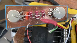
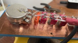
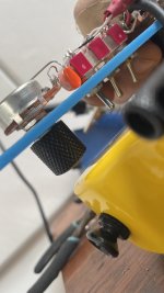
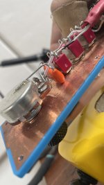
Need guitar potentiometer & volume wiring help

Pictures would be a lot easier to decipher in this case...

White and red wires: you're always going to get noise if your ground isn't connected well so make sure that is soldered on nicely. Then you've effectively just got a "hot" or live or signal wire. This is more or less linear and you can trace it forwards or backwards.

You can do work on a guitar while it's plugged into an amp and turned on,every safely. It might make some horrible loud noises if the amp is set too loud, but any electrical danger would be from a fault in the amp not your guitar. So get prodding with the thing plugged in and you'll soon find the issue!

For instance take a thin screwdriver or paperclip and hold it in your bare fingers so it's an extension of you, you big noisy antenna you. Now use that noisy poker to touch the output terminal on the jack socket. See how you can inject noise into the circuit?

Now move back along the signal wire and touch the volume potentiometer terminal where it's soldered. Same noise! Then you can switch over to the over terminal which is where the 3 pickup switches join on - you'll get noise, but only if the volume control is turned up! If you turn it down, it's stopping your finger-pokey noise from reaching the amp.

Use this method to trace connections until you have a clean line of signal from the pickup wire, through the switches and into the volume pot and then the jack.

Hint: the tone control is a parallel branch of this signal chain so you can sort of ignore it, unless your sound is all muffled constantly.

Bigger hint: all components should usually be grounded e.g. pickups, pots, bridge. Use a multimeter in continuity mode (beeps) to confirm this by checking against the guitar cable's sleeve/jack plug body.

Green wire: no idea, but I would expect there to be a bridge ground wire somewhere (unless those are active pickups). See if it has continuity with the bridge.
They're not active pickups, I know that much.

I do have a multimeter which is how I've been checking the tip and the sleeve are wired in correctly.

But I can't work out what these other wires do and it's really hard to get them connected by touching and then move the volume and tone.

I'm having difficulty understanding how it's wired; like whether the guitar input goes into the tone and then out via the volume or vice versa.

I've been doing exactly what you said but I'm alway getting noise no matter what I did.
Shall I make a video showing you? There's also that green wire and I have no idea what it does.

More photos? Video?
 
Personally I always run wires for ground to each potentiometer and don't rely on copper foil but it SHOULD work fine as is.


Having worked out what IS there - I don't see pickup grounds and there's a green wire coming out of the pickup wires bundle. So I'd bet a fiver that green wire needs grounding. Can you see where it came unsoldered from?
 
literal back of the envelope calculations. I love it.

I can't remember where it was unsoldered from BUT I can take a picture of the places it seems like something has come undone.
 
haha.
Ok.

So I've marked all the points I need.

1 - To TIP
2 - to SLEEVE
3 - green wire; you reckon I solder it to 6?
4. Place where wire has come loose I think .
5. another place where wire has come loose I think although it is also where 6 connects to 5
6. Place where wire may have come loose?
7. Tone POT
8. Volume POT.


6OMqVAY.jpg


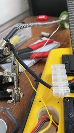
There is also a mysterious yellow wire that was wired into the SLEEVE too so I've soldered it there.

gvqoqKS.jpg
 
Per your diagram how does the signal travel from P1, P2, P3 to the tone and then back to the volume? I don't know what the three pins on each P do. Or which direction they go.
 
1 - To TIP
2 - to SLEEVE
3 - green wire; you reckon I solder it to 6?
4. Place where wire has come loose I think .
5. another place where wire has come loose I think although it is also where 6 connects to 5
6. Place where wire may have come loose?
7. Tone POT
8. Volume POT.
I think you've got this all right - 4 is the output of the volume control so presumably the jack wire came loose at some point.

If something came loose from 6 I imagine that was your green wire. Could be from 5, but usually I do as above and feed wire from the lug (5) to the back of the pot (6).

Then connect (1) to (4) and (2) to (6) or to 5, or any other convenient ground.

There is also a mysterious yellow wire that was wired into the SLEEVE too so I've soldered it there.
Probably the bridge ground wire if it just emerges from the cavity wall.

Per your diagram how does the signal travel from P1, P2, P3 to the tone and then back to the volume? I don't know what the three pins on each P do. Or which direction they go.
The red line is all one common wire so the signal exists all along it - three pickups and a tone control, all in parallel connected to the volume control. They're all just connected together.

Three pins on pickup switches: middle is the common/output pin. Then each side is connected only when the switch is up/down. In other words, the red line running through the middle is the "output" of the switches and along the bottom pins, is each individual pickup's signal wire. Each switch turns one individual pickup on/off.
 
lU20aOS.jpg

Soldered it all in and everything works great EXCEPT the tone knob now does nothing. Any idea what I've done wrong?
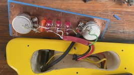
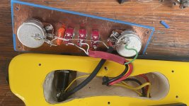
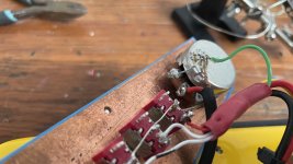
That capacitor is mounted in a very hairy "might easily short out and ruin the sound" way. Could you get a photo of that potentiometer so it's really clear what's going where?

It is!
I got someone to make it left handed. That doesn't change anything right?
Just makes you a wronghander :D Technically the potentiometers might have a right handed audio taper so they have uneven travel, but it's not a big deal.
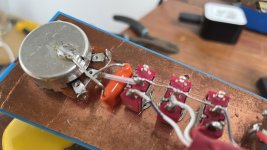
 
Looks to me like the capacitor has shorted a leg to the signal line, circled in red. If this is true the tone control would be "all the way down" all the time. So would sound dark/muffled.


I'd also keep an eye on the bit circled in blue, that's a bit close too. As I say it's not ideal layout so make sure nothing crossing over is touching, unless it's soldered.
 
Last edited:
Looks to me like the capacitor has shorted a leg to the signal line, circled in red. If this is true the tone control would be "all the way down" all the time. So would sound dark/muffled.

I'd also keep an eye on the bit circled in blue, that's a bit close too. As I say it's not ideal layout so make sure nothing crossing over is touching, unless it's soldered.
Ah the picture didn't come through.
 
Back
Top Bottom