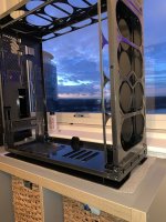
Project: Little Bit Big.

I'm not massively fussed about if its Chrome or Black - given the glass on the 1000D i'm not sure if you could see the difference. Is it the same model that is compatible with the Gigabyte Gaming OC 1080ti?

Do you need the chrome one or would a black one do? I have a used black block with the led lead that I might not need anymore if u might be interested

You might want to take this discussion via trust before mid action, given you cannot do it via members market...
 
I just don’t know why the eLoops are out of stock...

J2OlI1N.jpg

Now all I have to do is desolder and resolder 34 of them...
 
Last edited:
Waiting! - id love to see the build costs too! :)

Have a bunch of updates coming, I don’t really know the costs to be honest but the hardware was already owned so not sure I’d count that :)

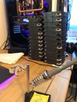
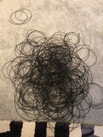
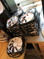
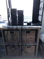
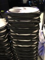
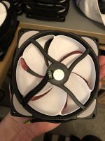
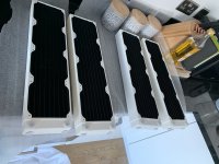
Currently the case is stripped bare and been modified, probably going to send it and parts for powder coating just deciding on colour choice. Radiators now all refinished white and there is a pile of 32 fans desoldered ready to resolder and braid on my desk... terrible job awaits but also finishing my apartment renovation so bit slow progress!
 
Also interested to find out. On my last build I searched ages for a company to anodise some heatsinks. WhenI finally found someone who would take on such a small job, the price was very reasonable :)

Yeah I think powder coating should be ok, need to finish some more mods on the chassis then I’ll ask. Literally 2 miles up the road there is one which looks decent.
 
Where do you send it for coating? Is it very expensive?

Also interested to find out. On my last build I searched ages for a company to anodise some heatsinks. WhenI finally found someone who would take on such a small job, the price was very reasonable :)

Quoted roughly £75 from somewhere up the road gents, colour choice to be confirmed but I’m coating the chassis and removable metal probably smooth gloss with metallic.

The tray and new res mount will then be covered by a Matt black thing sheet. Metallic grey/colour... thoughts?
 
Can’t wait to see the finished article. Looks mega already.

Me too, been struggling for time but works winding down now so hopefully get a few bits in next week. Possibly even get to the powder coaters and see about picking colour and how the metallic top coat looks!

Some pics to post so will most likely do that next week...
 
Well, long overdue proper update as promised... Been pretty hectic the past month or so but making some strides in to the base of the build. First up, the case... Well it doesnt quite look like the 1000D that was delivered:

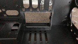
Drive bay removed and some areas cut out to get rid of some parts which get in the way of the res:
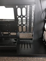
lvL1q5k.jpg
oClEEZJ.jpg

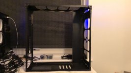
Since then its been stripped even further, the basic reason for this is for powder coating. It will be dropped off the get shot blasted/stripped clean and then powder coated probably dark in colour with a metallic finish:
xOhl3rN.jpg

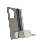
Seems pretty extreme I know but the glass panels are all separate and hopefully I can figure out how to put it together again :). Whilst doing this I've pretty well decided the board tray mount is quite flimsy and not exactly as I want it, so i'll be designing a new one which I will get machined in some much thicker brushed aluminium. I think this will look really nice in the middle of the new chassis, you wont see much of it but it will be far more sturdy and more fitting for things like board cable routes which currently do not align with the standard slots.

See parts removed, these will be coated also. The current plan above is likely to be the end result but i'll probably get the existing tray coated also as it wont cost any more money that the current quote.

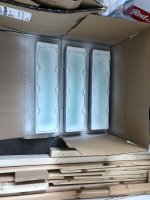
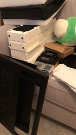
Whilst I've been doing other work on the apartment (new floor now in, you will see in the pics just some underlay and bathrooms finished) I've also completed the radiator sprays. You might recall from above that XSPC decided to stop doing runs of the XR series in white and after a month messing about they confirmed all gone so I got hold of 3 more in black and sprayed them all white. Now completed I have 4 matching white rads:
4pyuwul.jpg
0XNMgW6.jpg

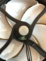
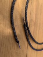
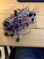
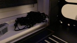
And on to the very long job, I have too many fans to go with these rads... And as above I wanted to rewire the short connected eLoops to a single long wire all the way to the Commander Pros (in pairs). This as predicted was VERY long to complete and crazy boring, but I have to say improved my own solder skills working in the tiny space. Long story short, 28 fans completed:

Remove short rainbow crap:
So9mPeQ.jpg
b8WWjMQ.jpg
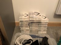
I now realise I have about 60+ fan extensions as each fan comes with 2... I'm not using any so will probably sell them off/give them away!
IHMTwgK.jpg
Cut to size a hell of a lot of wire:
KKZr8ZZ.jpg
Resolder 4 wires on each fan...
3s7RvMS.jpg
BTHzArL.jpg
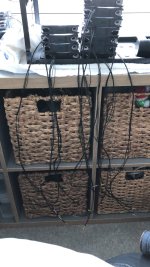
Group all the wires to make cleaner braids, also taping the colours to make the new connections easy - this took a lot of time...
BEMZq7c.jpg
OtZO0wK.jpg
But made the braiding much easier!
GnifHbW.jpg
upWhYOl.jpg
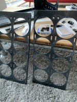
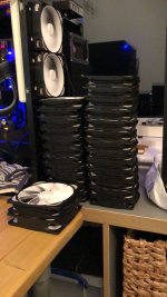
This read of the fan will be covered by an aluminium disc, for ease and exact fit i'm getting some laser cut as its only about £20 for the 30 odd i'll need, should look pretty clean as the braid is fit through the rubber grommet nicely.
hODQiqD.jpg
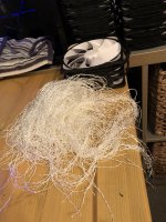
Paracord guts everywhere ;)
WHpV8DS.jpg

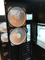
One other thing of note, as you will see in the snaps i've got 2 x 140mm as the rear exhaust fans for which there are rails cut to mount this or 120mm. However, two 140mm do not fit vertically within the rail limits which seems to be an error in the measurements if you see the top fan it sits over the end of the slot limit by about 10mm:
hFJ0b19.jpg
wsrrLqn.jpg

I dont have any other 140mm fans but I measured the 120mm Noiseblocker vs Corsair MLs and they are EXACTLY the same physical size. I assume then they cocked up the measurements and the channels designed for the 140mm were not extrapolated out as the width was, there is clearly room for the two and channels for two but looks like a mistake... I've since measured and drilled a hole above each which fits them both perfectly (a few plastic washers under the top two mount to create the stand off probably).

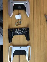
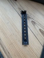
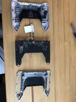
Next up, I own two 2080Tis. This probably makes some people angry, some laugh and some furiously type in the GPU section about AMD - call it what you will the cards are fantastic so far and i'm in it for the love of trying new things. This aside I dislike the NVLink bridge design against my metal build, so its been dismantled with a view to designing my own cover (which looks mega easy):

If anyone was wondering the LED is the small white panel, the NV logo actually pushes out so if you wanted a minor mod you could probably replace that with something of your choice:
oJcbrDx.jpg
5clG1ZC.jpg

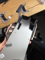
One of the blocked Dukes checking for the standoff and fit which looks ample:
onyKvTx.jpg
C0SPNK8.jpg

I'l not planning anything crazy, having seen the vendor bridges not really hitting the market fast its probably something a little like the Asus design but again brushed metal plate on top, there is probably room to get creative and put a temp display in there if you wanted ;)

So thats it for now, I need to sand a few parts of the chassis then off it goes to get coated. I've got more heat shrink arriving to finish the fan pairings as I forgot I only had white left, then those will be paired and fit to rads ready. The main things to work through now are:

  • Get the frame powder coating in metallic glossy goodness
  • Finalise the designs of the distro/res and whether I attempt to build the pumps in to it (tips welcome!)
  • Finish up the mega fan job, I need a few more most likely
  • Design a new board tray and get fabricated with the res - could be brushed alu or matt black acrylic like a Parvum case...
  • Fit the rads in to the new chassis and play with bending the black chrome tubing
  • Look at various parts in the base where I probably want to make panels to cover up some of the holes where other mounts formerly were
A slow project I know but one which is making progress ;)

Cheers!
 
Fantastic update.

These things take time but you are making good progress and I'm loving the detail in the description of the process and the accompanying photos.

I have a question about some fans that I have that you might be able to help with.
I have 9 pwm fans that i need to connect to my pc but they are going on an external radiator. I was thinking of using extensions and then connecting each fan to a controller, probably a thermaltake one since that is the only one i've seen that will 9 (10).

Since you are using so many, do you find you have any issues with controlling them? Does having 2 fans on one port create any problems with fan curve, or speed, or reporting?

And finally one you may not be able to answer, but may be able to test? Do you think it would be possible to daisychain x amount of extensions to allow a 3m connection from the external rad (controller) to the pc (a 4 pin to usb header connection i am guessing)? I understand that this wont look the best but since I don't solder it is an idea I am playing with. At least in the near term.

Please don't put yourself out trying to test for me, i realise that you have a lot going on so if it isn't possible no problem. Thanks for the update. :)

Howdy,

You could use splitters with fans in pairs or more. In the last build I had some Splitty9 which needless to say take 9, three of those with fans in to them and single outs to the controller. Outcome is that the controller can control the bank of fans on the splitter, with one in a designated slot to provide the tac feedback on RPM.

I would do something like that, in my eyes is fine as you tend to want to control them in radiator banks not as single fans - so guessing you have 9 on one of those big square rads. The key is to connect the read from just one in order to keep the PWM current speed, then the other wires are basically + and - and then a set speed. A splitter 9 would be my solution and they are about £9, short cables to that then one to a controller with the appropriate wattage on the channel.

Extensions you could do, simply connecting the wires is all it’s doing. That said you could easily get some wire and just make the extension up, connecting all 4 on the input to the controller. If it’s a long distance I believe higher AWG is advisable, mostly they seem to be about 24/26AWG on fans but you could do a run of higher quite easily and it’s just a fan plug on each end then - no solder required as you crimp on the connectors... I have a bunch so if you are stuck possibly make you one after Xmas.
 
Great build, dont think ive ever seen so many fans going into a pc build!

Tell me about it, with 4 x 480 radiators minimum fans would be 16 though :). I’m on the fence about push pull on the top radiators so will see when it comes together a little more...

Good fun though ;)
 
Howdy...

Long time no update, go side tracked eating and drinking all Xmas followed by illness and back to work! A few updates:

1. The frame and all parts is now at the powder coaters, i'm hoping to be able to get a sample piece next week to see if the colour I ordered is good and the finish looks ok. Looking forward to that!
2. Fans are paired and braided, working fine in testing and will be starting to mount on the radiators ready this week - long boring task they were but they look good. I will be getting Aluminium discs laser cut to replace the old stickers, this will be a little while as...
3. Design and get made new motherboard tray, although the old one is being powder coated its just flimsy and crap so i'll get a simple done when its back to replace with some nice thick 2-3mm aluminium.
4. Distro designs on hold until above is done for precise measurements but I have come to the conclusion I need to split the cable management from the res/distro for future proofing. For example when I change hardware I only need to get a simple acrylic panel recut not an entire sealed distro plate (I hope).
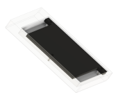
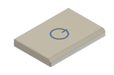
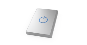
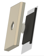
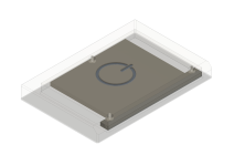
5. Custom NVlink bridge now started/designed, see below - this is to fit the insides of the NV standard bridge, the logo is TBC its just a bit of a meme which I was about to write RTX and the power icon :D

Slow and steady wins the race, I think... Designs finalised this morning:

8mWFO2r.png
19vAFzm.png
2lZPOQp.png
PxmnDhr.png
Ez33AjO.png
Pu4N4ax.png

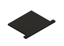
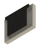
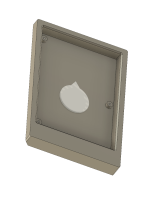
This will likely either be just black acetal with an aluminium/metal plate OR i'll just get the top bit milled in solid Aluminium, the internal back plate in acrylic pins it to the standoffs. If you are wondering its deliberately offset the be larger at the bottom, what this does is mitigate the offset you get from the natural fit of the link when attached as the bottom SLI fingers are at the top of the card... In short I hope this centres the bridge over both cards to the eye ;)

More to come next week I hope!!!
 
something like JB Weld?

Yeah pretty much but this is a specialist compound called Just4Copper or something lame like that. When you twist it in, if you followed the directions, you have about 5 seconds before its never coming out or turning again... Its tricky to work with but gives you confidence given you cant pull it apart no matter how hard you try even after about 2 minutes. Its supposed to be water resistant to 7 PSI within about 10 seconds as it cures super quick in the joint where there is no oxygen.

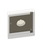
Few more shots of the NVLink bridge which is pretty much done, I've learnt how to translate this to drawings so will have a look at printing a 1:1 and checking my measurements before it gets made ;). The more astute of you will notice I was a weetard and had the bridge the wrong orientation so corrected that and added a simple logo in the centre, this will be frosted clear acrylic and lines up to the existing LED panel in the bridge so I can still RGB all the things.

nRR03Ac.png
M2BWRfY.png
qJTaeok.png

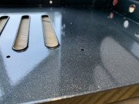
Now, its time to GET HYPED. Because I just picked up this sample from the multitude of bits left at the powder coaters, basically to confirm I like the finish before we do the whole job... I like. A lot. Difficult to get pictures but the former 1000D stock of matt textured black next to dark grey sparkle with gloss finish. The quality is well worth it vs. painting myself so i'm really glad I went this route - what do you think?

Old left, new right:
m5yUXJd.jpg

Sparkle is difficult to photograph but it looks very tasteful:
H1kq7DF.jpg

And under a strong white light in the bathroom to show the real life colour a little more:
FdjKn0e.jpg

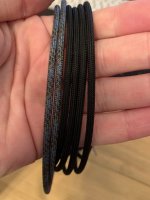
I cant wait to see the rest all coated up! While we are at it the new paracord colours are in, all the way from the USA - a massive thanks to Atwood Rope for not declaring the VAT paid and ignoring all my emails :D. So glad you were there to support me by ignoring all my communications and leaving me with about $20 charges to pay on $22 of rope. It looks good though, will probably be the odd single strand or two next to black matt. I've also been trying melting the ends to secure in place of crimping over the sleeve - works really well so this will be the new method for me, more reliable and no need for sacrificial sleeve as the para melts neatly and sets like rock.

Odd flecks of bright blue, bits of black and matching grey to the case:
Fw8tPMA.jpg
XAuSuAS.jpg

Did someone say progress? ;)
 
Looks good @Smffy colour looks like Skoda Grey, had my Golf R wheels powder coated in the same colour. Good choice. Keep it up mate.

Thanks mate, it’s a special colour blend, base is Matt black and then a top coat with the special flecked finish. Whole rig is now back and I’ve been rebuilding/riveting back! Will get some snaps up soon, managed to face plant some ice while skating so been out of action getting my head stitched up ;) (doh!).

More measuring to do and designing for more internal parts I’m going to replace... getting there!
 
Update time!!!

So the case parts (all of the various bits individually) are now powder coated, in the end the special colour was worth a few extra quid in my opinion as it gives a really subtle finish but a few white LEDs will show it sparkle ever so slightly. A few shots of the finish, hard to tell in these photos how different it looks but i've done a quick video also ;)

T1f6Ask.jpg
Yes even all of these coated...
ULomajn.jpg
Fan/Rad mounts:
sqx80K3.jpg
This shot shows the colour reasonably well, i've kept the 'foot' and the top as stock in the nice brushed dark aluminium:
PLjfFxz.jpg

Next up needed to flush out ALL the radiators, this was a fun hour... Have to say they cam out pretty clear really so kudos on that job XSPC:

ulr5oQb.jpg

Needed to test mount...
aPH4fd0.jpg
X9OZule.jpg
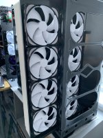
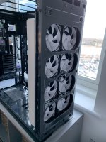
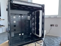
Added a layer of the push pull fans... I have some more to pair so will get those done in no time - they look very neat so glad I did all the work rewiring and braiding. However... I couldn't mount them as planned at the top with the mount tray inverted, so sadly I CANNOT fit 4 x 480 56mm radiatiors :(. Solution: I've got a pair of the 36mm and going to stealth fit them in the tray above as you can see here:
sLv7wW5.jpg


Its annoying but you cant quite get the radiator to sit on the tray mounts due to the lip at the side, I could design new trays but instead i've opted for the slimmer radiators hidden in the top tray. I will mod some hols through it to get to the ports, then a row of fans over it and it will look like it was all on purpose ;).

Right now i'm working on the designs to replace the board tray, i'm probably going to remove the old piece above the rear doors in the picture above again and just have a gap through which I think will be a good look. Its just been put back in with rivets so not hard to take out or change my mind.

The main design will look something like this:

U5OOLDQ.png
mbxqOFi.jpg

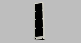
PSU shroud is completely done and measurements tested with a cardboard version from printed 1:1 drawings. The rest is early days but most likely i'll have two distro plates, the base one connecting in the front rads and back from built in D5's (x2) and the vertical one connecting all components and top rads before heading back to the pumps. work to do here but i'm currently focused on checking and rechecking the mainboard tray as its a crucial thing to get right. In order to then fairly accurately map out the distro plates i'm modelling other components which is really pushing my CAD learning to new levels but so far i've created the front radiator model based on XSPC measurements and some judgement:

mbxqOFi.jpg
j57n0qz.jpg

Done to scale to be best of my knowledge but drawings will be tested soon and anything which needs to be adjusted will be, pretty sure the ports are in the right place horizontally which is the main thing! Finally, see below video of a quite round the case to show the finish - sorry the size is a bit off just a quick job so dont go full screening it :D:

 
Back
Top Bottom