

Cheers. I've checked and it's currently limited and correctly set...but it still merrily plots moves beyond range. Trying to do a 2D Pocket instead of a faceing, it also plunges the whole tool and shaft through the stock and the bed...which is helpful. If you simulate with machine, it does at least spot there is overtravel and collision. I might need to reconfigure the Z axis limits as currently they're -30odd to +30odd which if I remember matches what the machine spits out but might not be helpful for programming.
You are using an out of date browser. It may not display this or other websites correctly.
You should upgrade or use an alternative browser.
You should upgrade or use an alternative browser.
Project: Silent Overkill
- Thread starter Cenedd
- Start date
More options
Thread starter's postsWell, time for some updates. Nothing too exciting but it's news at least.
Firstly, we are, at least in theory, moving house. "in theory"? Well, it's complicated. The sale of this house is all lined up...finally. The move date is set and our buyer can just about do that date before their mortgage disappears. Our solicitor has agreed the date with everyone...and THEN said that by the way, we might not be ready to buy the new house by then. *facepalm* So yeah, at the moment it's pack-and-pray.
So onto directly related stuff. I found that the nice relay I'd built into the CNC's PSU to start and stop the router works nicely....apart from the fact the router refuses to spin when you restore power with the switch turned on. So, some open-router surgery, new flex and we now have both a switched live and a permanent live. Restart protection bypassed and it works nicely. At some point, it might be possible to do speed control if I essentially remove the pot and substitute in something providing the voltage level it's looking for. A project for another time though.
I worked out the CAD issues so that the Z coordinates aren't crazy and I worked out how to constrain it to an area so it doesn't go out of bounds. But oddly, it left an uncut ridge on the CAD. Whack in a negative amount of stock to leave and bam, perfect....except now the coordinates are negative again. So somehow, despite carefully calculating it all, I can't get right to the edge without hitting the limit switch and having it e-stop. I had a play but it's not going to work....so I escalated things
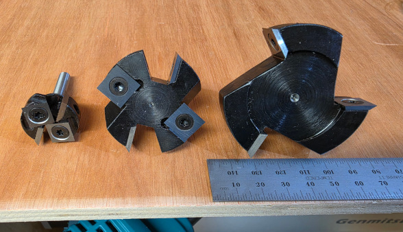
If 45mm won't reach, maybe 60mm will! I've turned down the 12mm shank (that won't fit in the collet on my router) to 8mm. Is that wise for a cutter this big?! No, almost certainly not...but then it's only going to be taking a very shallow cut in some quite soft plastic...so I reckon it'll be ok.
We've got this weekend and next before we have to move...so I suspect that making chips is going to have to wait until after that...and after moving in...and after getting stuff sorted...and...and....ah, I'll get there someday!
Firstly, we are, at least in theory, moving house. "in theory"? Well, it's complicated. The sale of this house is all lined up...finally. The move date is set and our buyer can just about do that date before their mortgage disappears. Our solicitor has agreed the date with everyone...and THEN said that by the way, we might not be ready to buy the new house by then. *facepalm* So yeah, at the moment it's pack-and-pray.
So onto directly related stuff. I found that the nice relay I'd built into the CNC's PSU to start and stop the router works nicely....apart from the fact the router refuses to spin when you restore power with the switch turned on. So, some open-router surgery, new flex and we now have both a switched live and a permanent live. Restart protection bypassed and it works nicely. At some point, it might be possible to do speed control if I essentially remove the pot and substitute in something providing the voltage level it's looking for. A project for another time though.
I worked out the CAD issues so that the Z coordinates aren't crazy and I worked out how to constrain it to an area so it doesn't go out of bounds. But oddly, it left an uncut ridge on the CAD. Whack in a negative amount of stock to leave and bam, perfect....except now the coordinates are negative again. So somehow, despite carefully calculating it all, I can't get right to the edge without hitting the limit switch and having it e-stop. I had a play but it's not going to work....so I escalated things
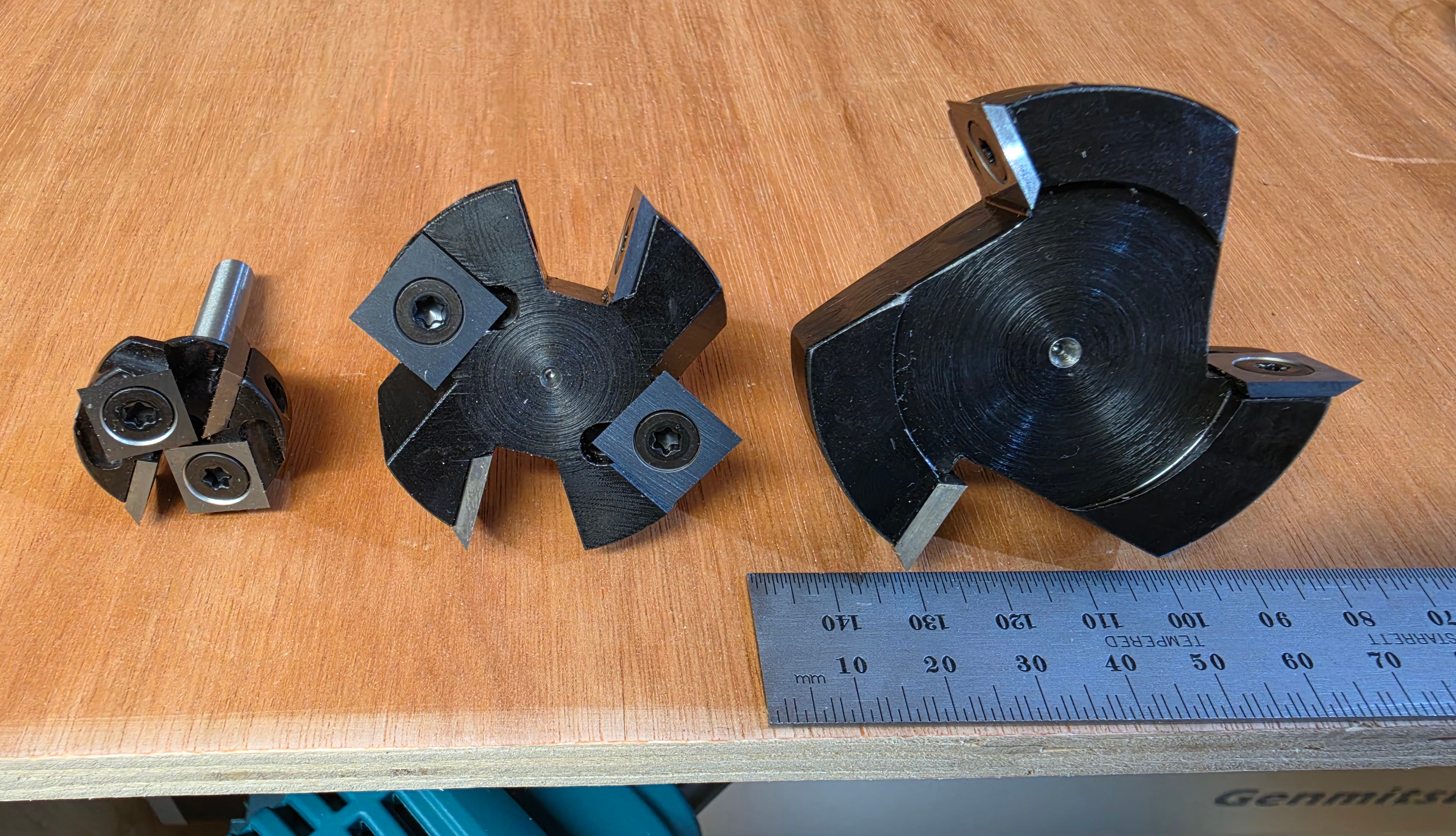
If 45mm won't reach, maybe 60mm will! I've turned down the 12mm shank (that won't fit in the collet on my router) to 8mm. Is that wise for a cutter this big?! No, almost certainly not...but then it's only going to be taking a very shallow cut in some quite soft plastic...so I reckon it'll be ok.
We've got this weekend and next before we have to move...so I suspect that making chips is going to have to wait until after that...and after moving in...and after getting stuff sorted...and...and....ah, I'll get there someday!