Project: Silent Overkill

Ok, I'm calling that finished!


Fits in rather nicely.....


.....until you turn the lighting back on :(


Checked and the blue of the RGB LEDs is shot in the GPU and the res. CPU and pump block are ok. So now to contemplate whether to replace them. It's not just that I'm being lazy (although that's certainly some of it!) but now the room has been moved round, the window of this case it almost up against another PC.....so I'd do all the work and not see the colours not clashing any more. :-/
 
Is that 550 paracord? Do you find it a little too big, even when tight? I'm using some thin wall 17 AWG for my main cables and it's a touch thinner than stock cable, and I find the 550 paracord is positively baggy and just won't get nice and tight even at maximum stretch. I've dropped down to 425 for my main cables and it's nicely snug now.
 
Holy crap you finally did the 24 pin.

/faints.

Hey, I said I'd get round to it "eventually" for a reason :D

Is that 550 paracord? Do you find it a little too big, even when tight? I'm using some thin wall 17 AWG for my main cables and it's a touch thinner than stock cable, and I find the 550 paracord is positively baggy and just won't get nice and tight even at maximum stretch. I've dropped down to 425 for my main cables and it's nicely snug now.

Yes, it's 550. On some maybe. Since I started with a pre-made extension the wires were somewhat different gauges....or at a minimum the insulation was very varied. Some thicker and stiffer than others at least. For a proper attempt you'd definitely want the wire all the same thickness and probably more flexible than some of mine. You'd also want to consider how it'll be bent as if it's only one bend, you'll need to have the wires on the inside of the bend slightly shorter. I got away with it by making it enough of an S-bend that it evens out. There's some definite OOSOOM going on behind the rear door right now :D
 
Might have bought myself some fans to replace the Aerocools that I try not to let spin. They're small and subtle! :D That's a 120 for comparison.


Waiting on a fan grill that'll take the thicker fans as these are a fairly standard 30mm thick and the existing grill will only take up to 25mm.
 
It's hard to go wrong with Noctua fans, especially now that they've recognised that their traditional colours aren't to everyones taste when putting together rigs with the hardware on display.
 
I'll confess to exactly that. I think I actually paid extra for it not to be in the browns. I suspect that's the extra expense of the coloured rubber (TPU?) corners given that there's 8 in each of 6 colours. I'm going black at the moment - did consider a splash of colour but it's going to be a black fan against a black mounting board with a black grill.....and I'd never settle on a colour. I'd go blue but then I'd have to replace all the failed RGB LEDs in the main section that have popped their blue - as is, I just changed to green.
 
Yep, same for me. That said I think if you're locking in a colour pallet with custom cable sleeves then choosing one of the coloured corners that ties in probably makes some sense (I did exactly that, albeit with their black industrial fans in my Core v21 build), but otherwise neutral black is the obvious choice.
 
Last edited:
No, NO! I can't rebuild the case so it's inverted so the window is on the visible side (after a room reorganisation)! That's just crazy talk. Yeah, but I dug out the CAD and checked :confused::eek: It would mean flipping the res, all the drain ports in the wrong place. No, not enough spare sanity....or enough to realise it's a bad idea, depending on your take on it!
 
Hmmm, considering I was hoping to replace the existing fans with better ones, I didn't exactly make it easy for myself!
Fans: https://www.overclockers.co.uk/forums/posts/29493382
Wiring: https://www.overclockers.co.uk/forums/posts/29720336
3-pin wiring when the controller supports 4. Forward-thinking at it's finest.
Fans soldered instead of plugged - for reasons of clearance, to be fair but I've got some motherboard style 4-pin headers on order which will fit in the gap.
Female fan connector where it plugs into the case when it ought to be male. This, I'm pretty sure I did so it wouldn't short out against the rad fins if unplugged (it's also a motherboard style header rather than enclosed plug) but it doesn't make things easier!

So, having chopped the hard-wiring to get the fans out, I am obliged to push forward. New grill has arrived, fans are fitted and I've got temporary wiring to make 3 of them run as voltage controlled for now. Thought they might have been louder than the old....but that's at a full 800rpm when the old ones were 540rpm max and throttled down to 33% so may have been (I forget to be honest) around 380 - 400rpm.

I'll add pictures once I have things wired properly and not just jury-rigged and propped against the case :D
 
Thanks Doug. That's a fair amount of dedication making it through 18 pages of my ramblings!

Still waiting for 4-pin motherboard fan header style connectors to turn up. Those are slim enough to fit in the gap between the fan panel (metal panel with four 200mm holes cut in it) and the rad so there isn't a tangle of wiring on constant display. The normal enclosed style are nearly twice as thick and just won't fit without damaging the fins.
 
Well, the 4-pin headers arrived and I set to it. Nope, with the 22AWG wire I've got, I can't get four of them down a sleeve. So I checked ampacity, expected draw and what Noctua are using in their extensions and it only needs to be 26AWG. Ordered, arrived, not thin enough as I ordered the nice stuff with the silicon insulation :-/ Also, discovered I only have four fan pin crimps left and need eight, assuming no fails. Bah, what IDIOT is running this project?! :rolleyes::mad:
So now, there's an OCUK order waiting to ship with some fan pins and a selection of sleeving that (one of) should accommodate the wiring. I'll take some pics once OCUK have finished compensating for my complete lack of planning!
 
Once you've finished having a word with the Project Manager you might want to have a word with Stores or whoever else it is that is responsible for keeping consumables in stock. :)
 
Well, stuff turned up in the end. I ordered two sizes of sleeving just in case it was still too small but the smaller was fine in the end.


I can't say that it's my finest work but this is what you get when you fail to plan anything and just wing it!
I tried initially to solder to one connector and then daisy chain off there round the circle but it's fairly close and quickly becomes (as you can see!) a tangle of wires. In the end, I dismantled it and split them all off from one feed. The connectors and a lot of the wiring are hot-glued down in an effort to keep the thickness to a minimum so the plate can be screwed back onto the rad without taking chunks out the fins.
In theory, with a bit of faffing about with more hotglue (the fan's connectors are currently glued down instead of the feed's) I can swap out a fan if necessary.


Tested it quickly yesterday and the fans spin up....mostly. One or two of them take a few attempts to start even at 12V. I'm not sure if that's normal for these fans - the rotor is fairly heavy and they are deliberately fairly low powered - or if it's an issue with the amount of current draw. I went with 26AWG for this section to fit in the sleeving. In theory that should still support ten times the current the fans draw when running (as opposed to starting - but still nearly 7 times rated max). This is on voltage control though (but at full power) since the feed from the controller is still 3-pin. I started making up the cable to replace that but getting it threaded through the rad is somewhat tricky. To get enough clearance to thread the wire between the rads fins and case, it needs the case to be gently pried away....and that requires removing a screw from each side of the frame. No problem.....for one of them! The other would, I think, require removing the rad from the case to get at the screw...and that would require a complete drain. There's part of me saying that it's the proper thing to do.....and a big part saying that it can't be bothered! I may reassemble for now and think about it at next drain time.
 
Oh, and in case I haven't mentioned it: which idiot made everything black?! Have you tried working on black wiring against a black background, in a black case on a black carpet under a black desk? It's frustrating enough without the constant cries of "I can't see $*%^!" :mad:
 
Well, it turns out that bloody-mindedness won out. You see, if you're just that stubborn, you CAN get a screwdriver bit on the end of that screw - just the bit mind, not the entire driver! Then turning by spanner until it's loose enough to hand turn and JUST comes out before the driver bit is stuck against the side of the PC. Getting it back IN again though....well, that was just a delight once the internal holes didn't quite line up!

Screw marked in red. Picture from the back looking up.


You can just see the sleeving for the new cable to the right of the arrow. In the picture below you can see where that cable reappears at the bottom of the fins. You can also see that some idiot managed to clock it 90° out and had to reroute that cable (that was luckily slightly too long previously!) so that it pointed downwards. The panel only fits on the right way up - or 180° out.


and mounted


And with the grill back on.


I made the feed from the Aquaero to the rad with 22AWG wires for the ground and 12V and 26AWG for the tacho and PWM just in case. Didn't seem to make any difference and some fans still seem to take a couple of attempts to start. At least being PWM, it will always apply 12V with the lower speed limit (about 312rpm) being set by the fan - ie, you give it a lower duty cycle than 45% and it just ignores it and runs at 312rpm. Max is 800rpm (nominally - actually seems to be clocking 725) and that's fairly audible. Not disturbingly so though. I've got them set to come on at 36°C coolant temp and run at their slowest speed until 37°C from where they step straight up to 100%. They don't switch back off again until it drops below 35°. Previously they'd come on a time or two during office use and periodically during gaming. I don't think they ever ramped up from the slower speed though but if necessary I can either tweak the slowest speed or have them ramp up more gently from there.

Well, have a good Christmas all - if that's not a taboo subject now!
 
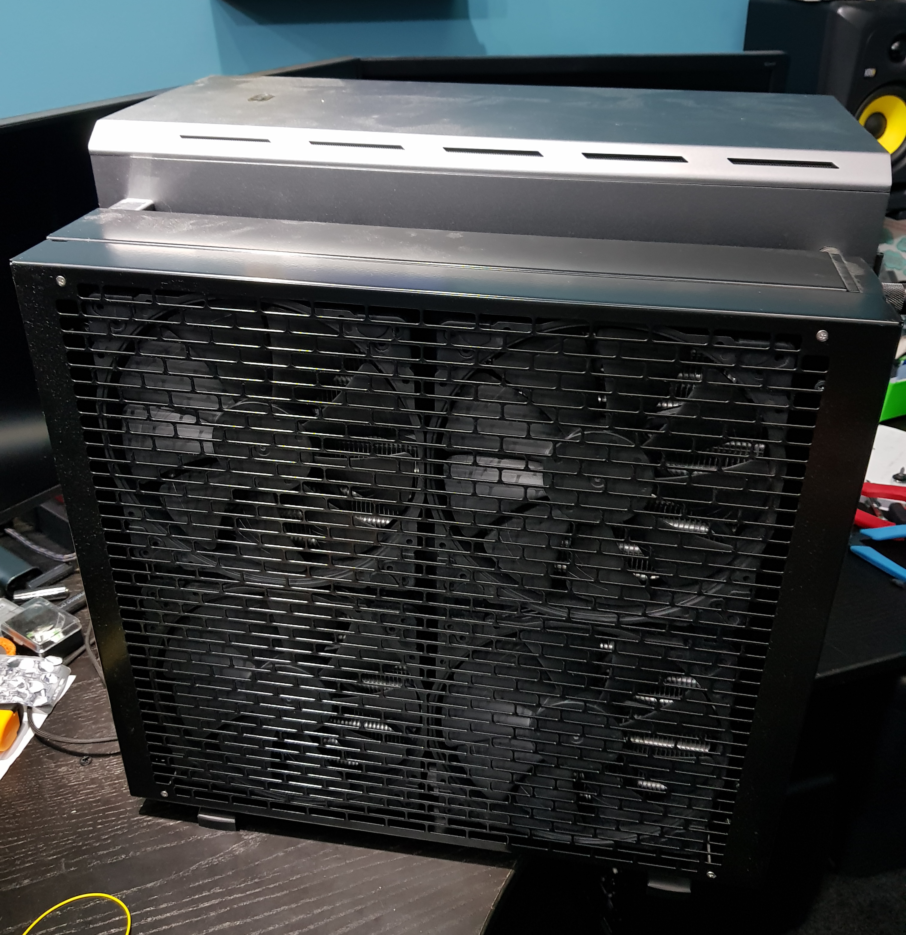
Well, another year gone - hmmm, that brings this PC to nearly 6 years old already. Must be time to put a new head on Trigger's broom! :D 
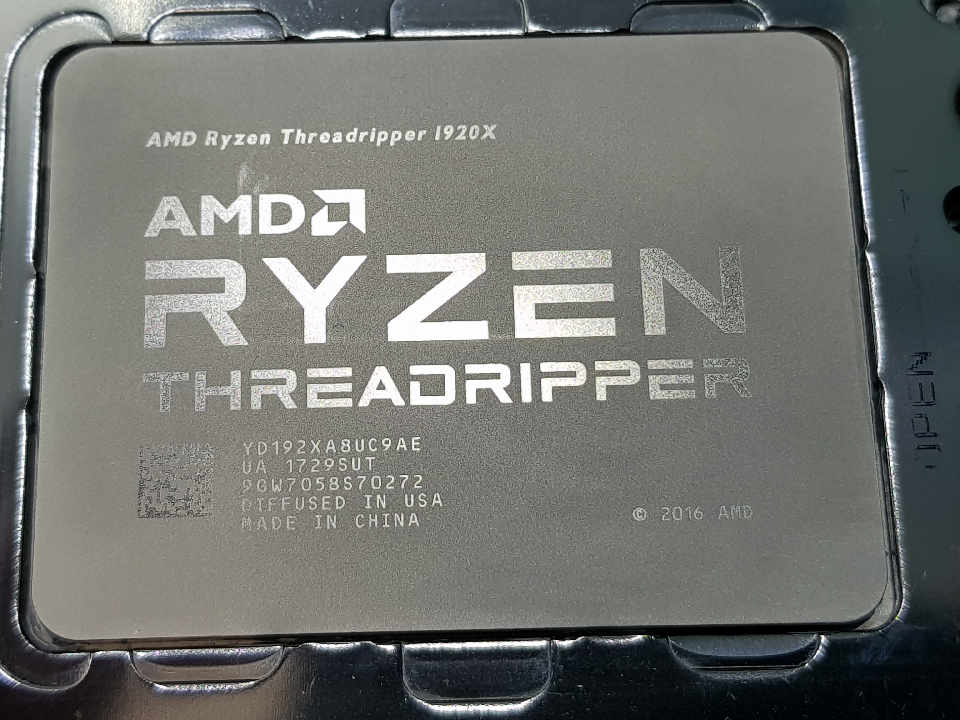
So, I have sitting here - courtesy of 
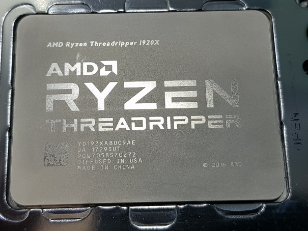
@ALXAndy - a Threadripper 1920x on an MSI X399 Godlike with a Bykski water block. It'd be rude not to put it to good use! :D


Glad I ordered another gramme of Kryonaut as that's the ENTIRE tube right there!
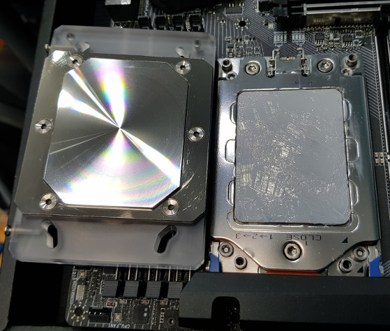
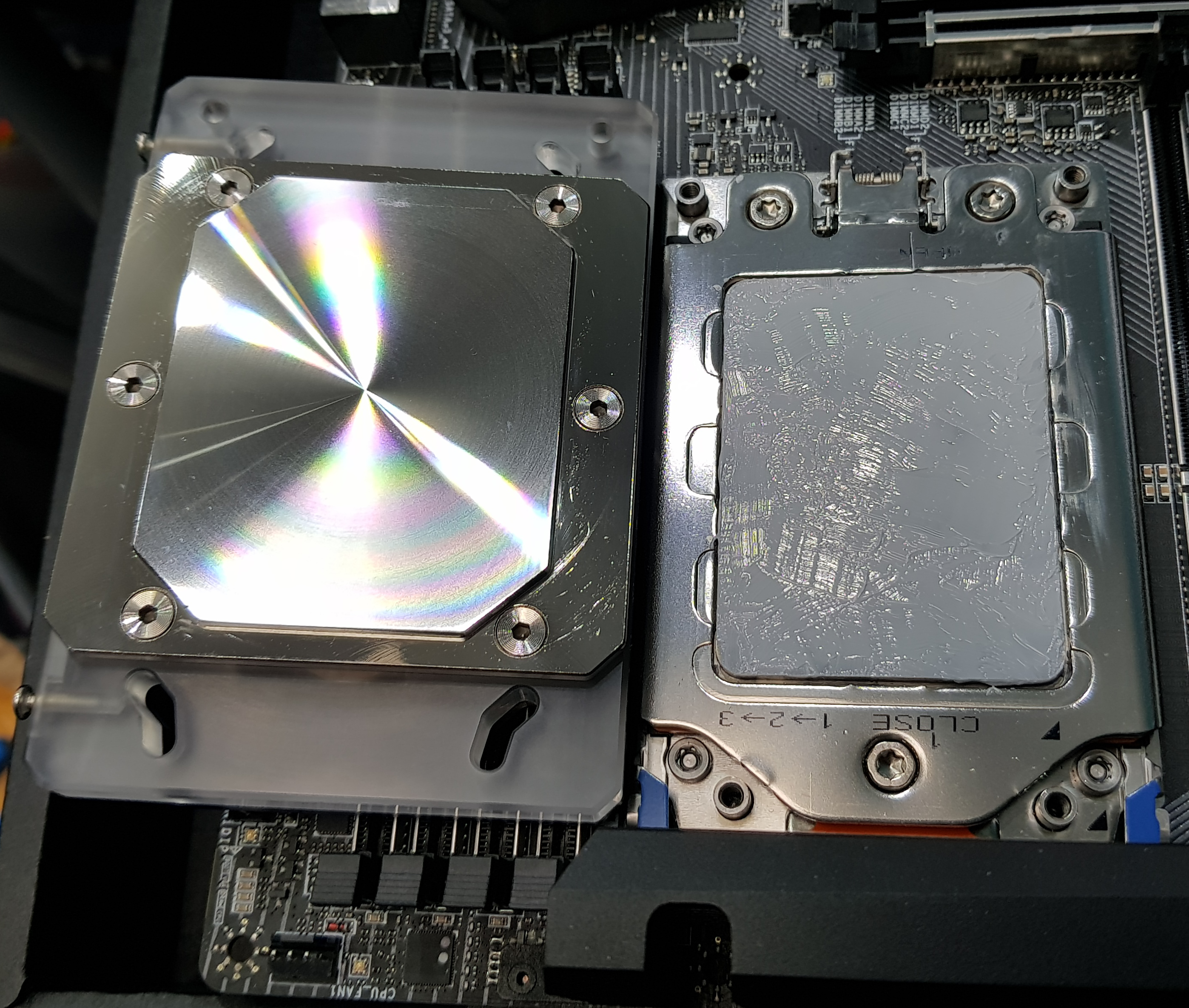
I'd not heard of Bykski but you can't argue with the surface finish of that cold plate :D
Incidentally, I cleaned the inside of the block (previously had black coolant in it) and pressure tested it for paranoia's sake.
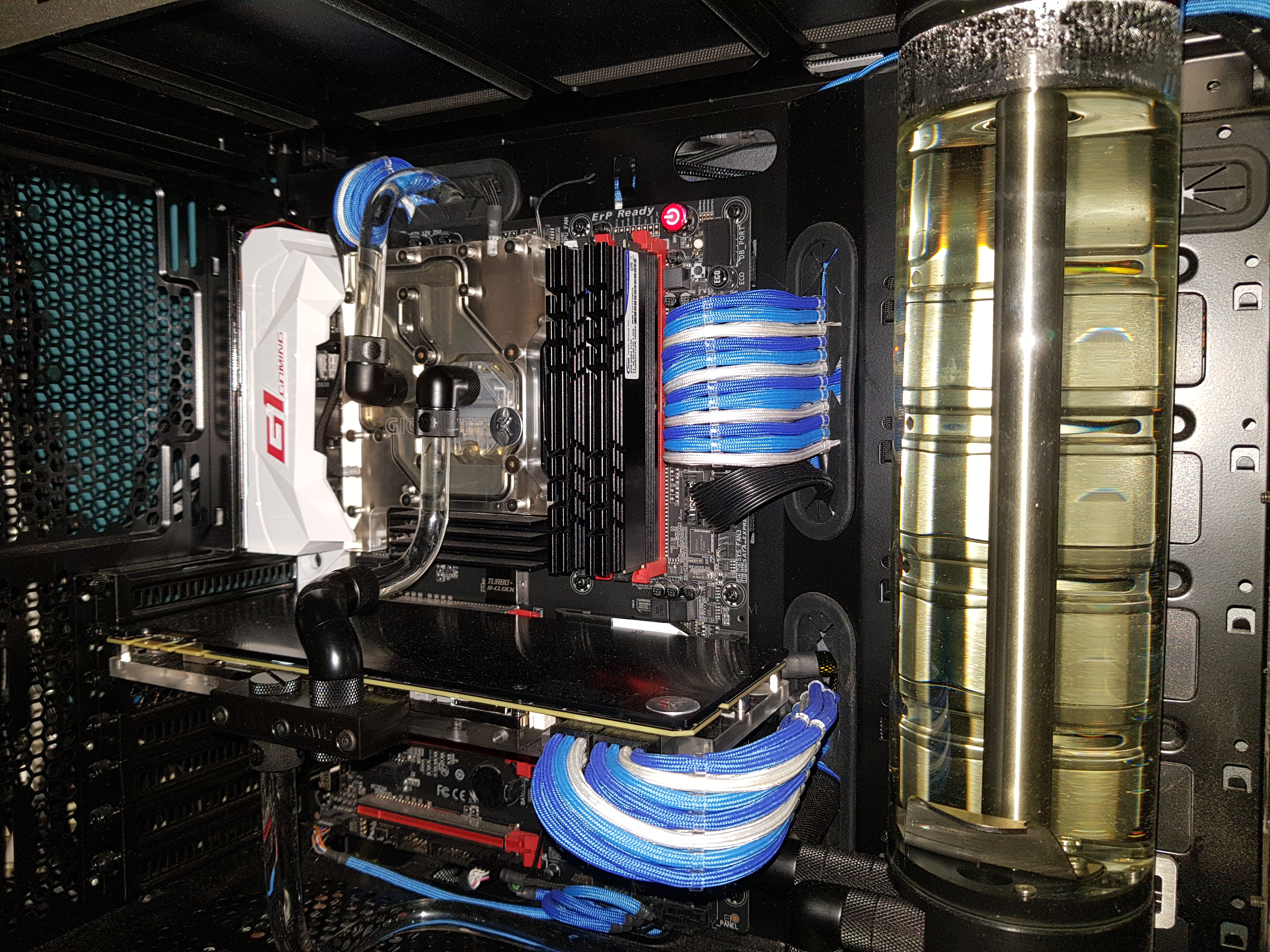
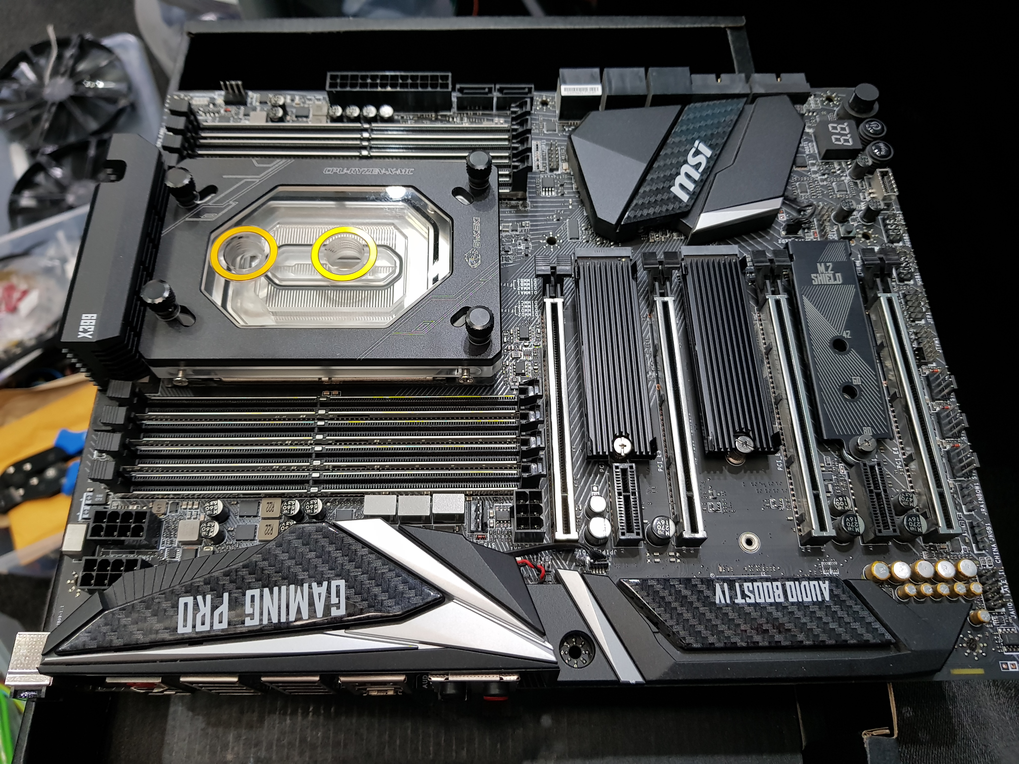


And all together:


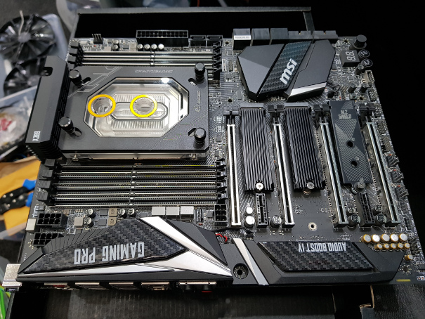
That's a pair of 1TB Black Friday special M.2 SSDs under those heatsinks. Probably overthinking it but the M.2 Shield (one on the far right) didn't seem to offer much in the way of heat dissipation so I replaced the two that have actual disks under them. Yeah, I'm surprised I didn't populate all three too! :D

The sharper eyed of you might have noticed TWO EPS power connectors in the bottom left and also a PCIE power connector by the PCIE slots. From what I can find, the PCIE power is only really required if you're going to be doing excessive things to the GPU or running several of them. As I'm not, I'm going to plan to leave that unused. The second EPS connections seems to be one that's recommended.....and guess what my PSU doesn't have! Can't have the PC down (used for both work and recreation) for too long....and so begins Project Procrastination!

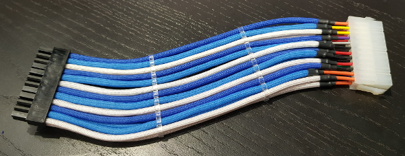
My PSU does have many spare PCIE power sockets which are almost identical to an EPS connection - in fact it actually uses the EPS connector but the wiring is PCIE stlye - ie 3x12V and 5xGround when EPS is four of each. I should be able to make up a secondary EPS connector and run it off that by just forking one of the 12V lines. All I need are some ATX crimp pins....which I can't find. Ordered some more....and forgot the shells they go in. Ordered those....and failed to get one for each end of the cable. Yeah, I'm on a multi-day roll! Where's the facepalm smiley when you need one?! *facepalm*
 
That's not the Godlike. That was the 2011 board I sold you haha. That's the Carbon ;)

Glad you're finally getting it sorted. He's had it ages BTW, came down and got it in the summer *grasses*. I didn't trust that heat shield either. I had AC sinks on the drives I had in there.

In hindsight I wish now that I had buffed off the writing on those carbon bits with some plastx. Would look so much better with that gone.
 
So it is.....told you it was a facepalm kinda day! I'd think about buffing the writing off....but since my office was reconfigured to use the space better, the window in my PC is actually facing another PC and hence I can't see anything of it but a green glow. Could really do with one of those inverted cases.....but I'm not starting from scratch now!
 
Back
Top Bottom