

You are using an out of date browser. It may not display this or other websites correctly.
You should upgrade or use an alternative browser.
You should upgrade or use an alternative browser.
Project: Silent Overkill
- Thread starter Cenedd
- Start date
More options
Thread starter's posts")
Replacement fan ordered. It's a 30mm fan (yeah, really!) with no speed control and driving me nuts whenever the power is on. Was looking up what sort of cfm a 30mm fan pushes just so I wasn't downgrading it and stumbled upon a seller who described (honestly, to be fair) it as
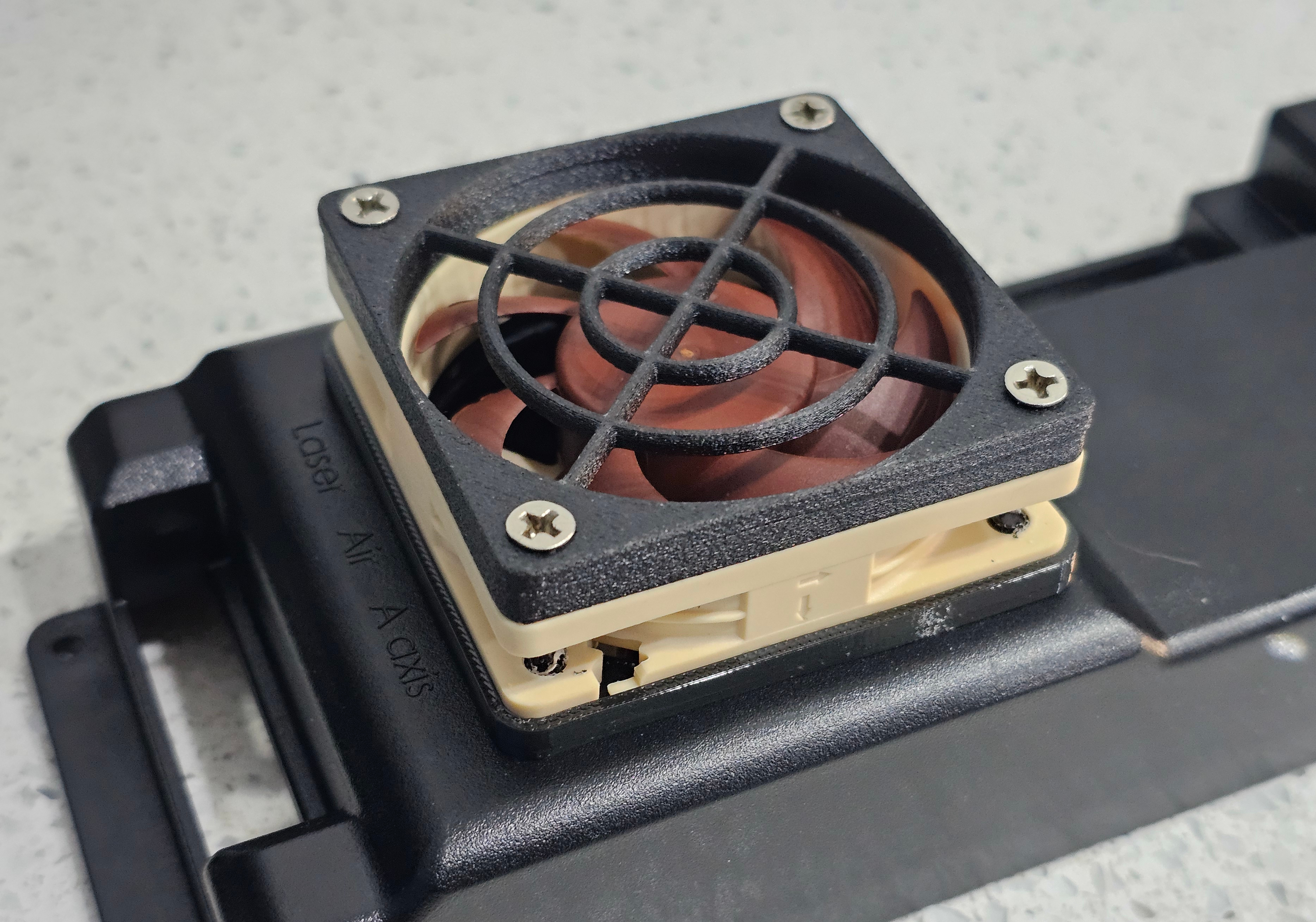
...and that's exactly why I want to change it! A nice Noctua at 60mm will fit and push about twice the cfm....but quietly. I think it would technically fit inside the existing case but I'm planning to mount it externally just for some extra space. Might have to print a TPU gasket to seal it. Don't they sell those? Yeah but at over a tenner, I'm printing my own! Might have to print a finger guard too as the chances of having a 60mm in stock are slim....and I'm not ordering one either!
Reason for taking it apart in the first place was actually to see if I can tap into the Z axis limit switch. I've got the touch probe (temporarily) wired as well as the tool setter. Those are all on the probe input. The tool setter also has an over-travel switch (basically to stop it crashing if it doesn't register) and the easiest thing to do with that is hijack the Z axis limit switch. Tell a lie the easiest thing would be to cut off the extra wires and ignore it....but that's not happening!
Was also wondering if I could run a mains relay off the 48V output to the spindle. Would let it turn the router on/off but only give me manual speed control - which is a step better than the current situation where I'm bound to eventually start a cut without the router turned on! *P'TWANG*
It's noisy (most small fans are), like "I don't want to sit in the same room as this damn thing" noisy.
...and that's exactly why I want to change it! A nice Noctua at 60mm will fit and push about twice the cfm....but quietly. I think it would technically fit inside the existing case but I'm planning to mount it externally just for some extra space. Might have to print a TPU gasket to seal it. Don't they sell those? Yeah but at over a tenner, I'm printing my own! Might have to print a finger guard too as the chances of having a 60mm in stock are slim....and I'm not ordering one either!
Reason for taking it apart in the first place was actually to see if I can tap into the Z axis limit switch. I've got the touch probe (temporarily) wired as well as the tool setter. Those are all on the probe input. The tool setter also has an over-travel switch (basically to stop it crashing if it doesn't register) and the easiest thing to do with that is hijack the Z axis limit switch. Tell a lie the easiest thing would be to cut off the extra wires and ignore it....but that's not happening!
Was also wondering if I could run a mains relay off the 48V output to the spindle. Would let it turn the router on/off but only give me manual speed control - which is a step better than the current situation where I'm bound to eventually start a cut without the router turned on! *P'TWANG*
I fitted tiny Noctua on my 3D printer they are amazingly quiet, I even stacked a couple on the heatsink to ramp up the pressure and still quiet as hell. Some 40mm I think so slightly larger on the main board. Highly recommended!Replacement fan ordered. It's a 30mm fan (yeah, really!) with no speed control and driving me nuts whenever the power is on. Was looking up what sort of cfm a 30mm fan pushes just so I wasn't downgrading it and stumbled upon a seller who described (honestly, to be fair) it as
...and that's exactly why I want to change it! A nice Noctua at 60mm will fit and push about twice the cfm....but quietly. I think it would technically fit inside the existing case but I'm planning to mount it externally just for some extra space. Might have to print a TPU gasket to seal it. Don't they sell those? Yeah but at over a tenner, I'm printing my own! Might have to print a finger guard too as the chances of having a 60mm in stock are slim....and I'm not ordering one either!
Reason for taking it apart in the first place was actually to see if I can tap into the Z axis limit switch. I've got the touch probe (temporarily) wired as well as the tool setter. Those are all on the probe input. The tool setter also has an over-travel switch (basically to stop it crashing if it doesn't register) and the easiest thing to do with that is hijack the Z axis limit switch. Tell a lie the easiest thing would be to cut off the extra wires and ignore it....but that's not happening!
Was also wondering if I could run a mains relay off the 48V output to the spindle. Would let it turn the router on/off but only give me manual speed control - which is a step better than the current situation where I'm bound to eventually start a cut without the router turned on! *P'TWANG*
Definitely. Ran a couple of 40mm Noctua's on my first 3D printer. Hotend was quiet but layer fan wasn't so I ran PETG and left it off 99% of the time. Not Noctua's fault, a weird implementation of PWM by Creality so they chopped the ground in very course divisions and it made it sound awful. This one I've got more space and weight isn't the issue it was on a hotend so I can go up to the dizzying heights of a 60mm fan Just designing the gasket for it now...obviously before I have the fan in my hands to measure!
Mind you, harping back to 3D printers, I've just realised I'm back in the same boat there. I could use the CNC to cut a nice circular hole and screw holes in the case...but the case holds the controller so the CNC doesn't currently work. Its 3D printer control board upgrades all over again! *facepalm* Might be time to get the adjustable hole cutter out for the manual mill. Why don't I use it often? 'cos it's damn scary, that's why! More so as the size goes up and on thin stuff. So yeah, if this thread goes quiet, you know what happened!")
Just designing the gasket for it now...obviously before I have the fan in my hands to measure! Mind you, harping back to 3D printers, I've just realised I'm back in the same boat there. I could use the CNC to cut a nice circular hole and screw holes in the case...but the case holds the controller so the CNC doesn't currently work. Its 3D printer control board upgrades all over again! *facepalm* Might be time to get the adjustable hole cutter out for the manual mill. Why don't I use it often? 'cos it's damn scary, that's why! More so as the size goes up and on thin stuff. So yeah, if this thread goes quiet, you know what happened!
Some progress for you. Complete? No, waiting for parts. Need some JST-XH connectors to finish up. Yes Andy, I could cut them off the existing fan and solder it on...but I refuse!
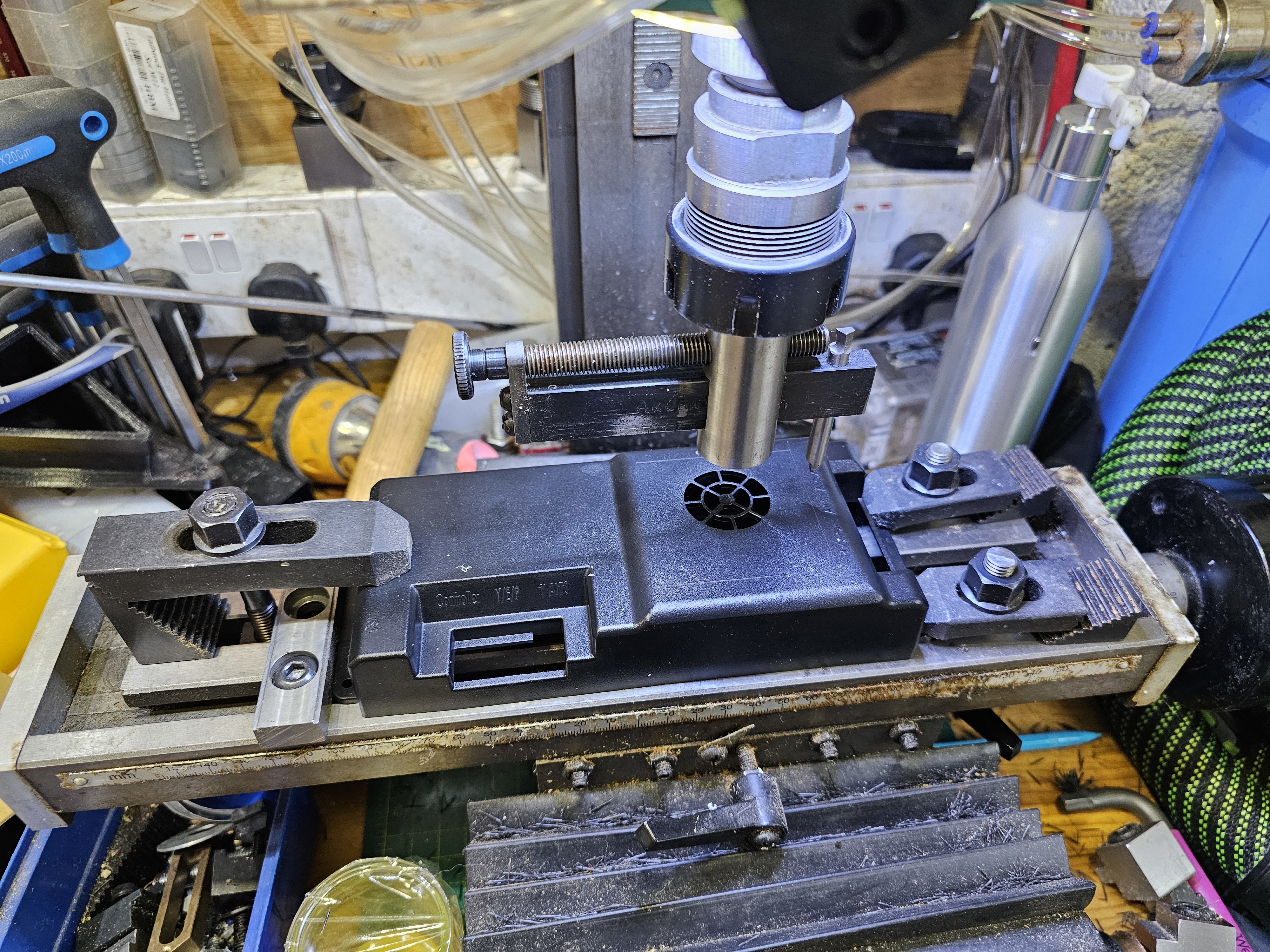
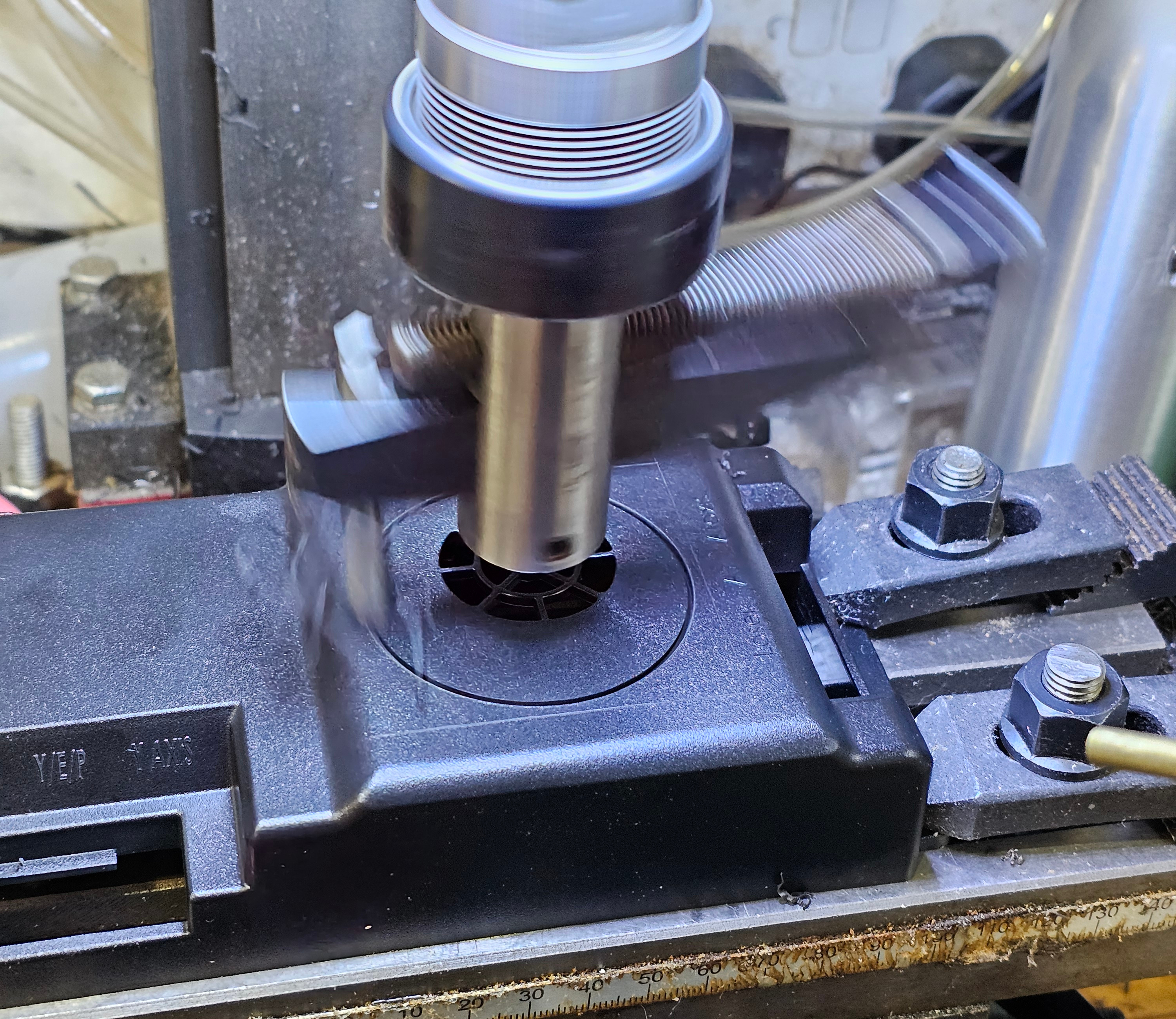
So this is the infamous vintage adjustable hole cutter. 1/4" tool bit ground in a fashion I don't hope to be able to touch-up let alone recreate. 12mm shank and pilot....'cos they were half inch and needed tidying up
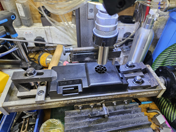
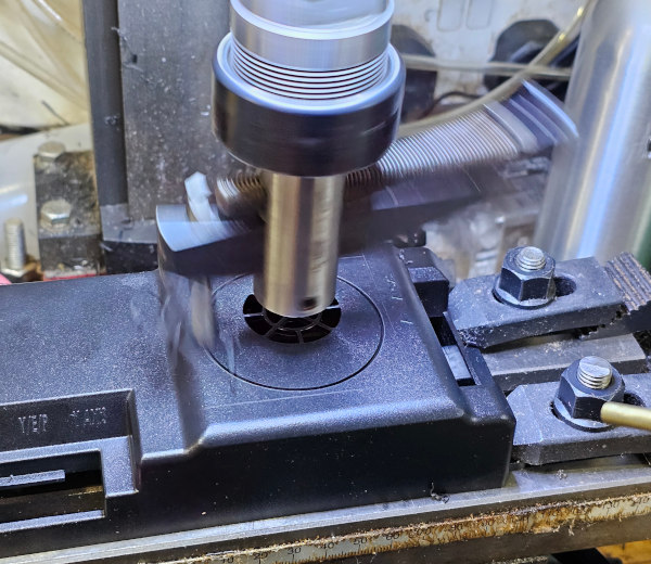
...and this is why it's terrifying! Slowest speed it'll run at and that blur is with a high enough shutter speed (1/50 or 0.02sec) that most moving stuff will be almost still. Eye protection (always) as you can't game without eyeballs. Even wore thesexy woman-repelling leather apron. Cowardice/prudence...I'll leave you to decide!
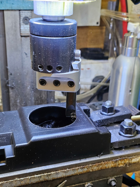
Wasn't getting reliable adjustability for diameter on that and the edge of the hole was somewhat rounded over. So I set up a boring head (which can enlarge an existing hole/bore and is adjustable in tiny, graduated amounts)...and immediately overshot the diameter by 0.25mm Not that it matters in this case but still.
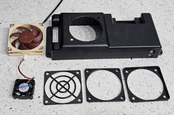
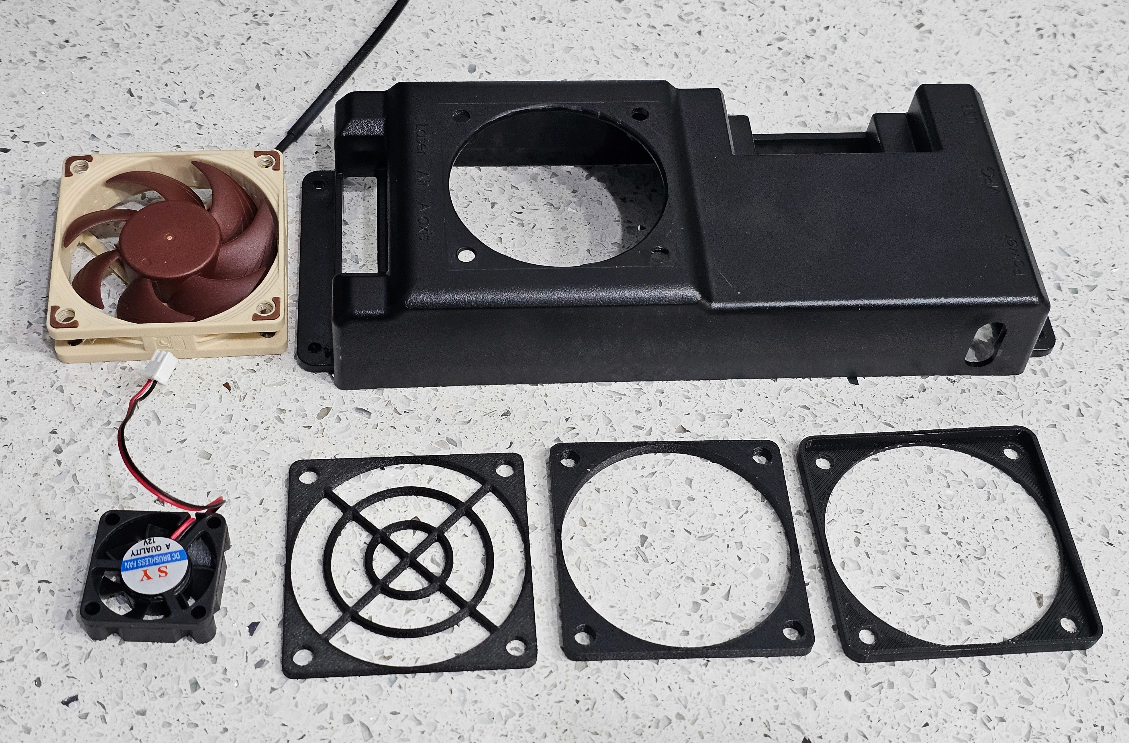
Clockwise from top right: Case with new holes, new fan, old fan, guard, spacer, gasket.
...and assembled.

Got the 2mm silicone o-ring cord delivered. It looks....dirty. I'll try the high-tech fix of warm water and Fairy and see if it comes up to scratch. The whole point was for it to look less visible than black, not look manky!
So this is the infamous vintage adjustable hole cutter. 1/4" tool bit ground in a fashion I don't hope to be able to touch-up let alone recreate. 12mm shank and pilot....'cos they were half inch and needed tidying up
...and this is why it's terrifying! Slowest speed it'll run at and that blur is with a high enough shutter speed (1/50 or 0.02sec) that most moving stuff will be almost still. Eye protection (always) as you can't game without eyeballs. Even wore the
Wasn't getting reliable adjustability for diameter on that and the edge of the hole was somewhat rounded over. So I set up a boring head (which can enlarge an existing hole/bore and is adjustable in tiny, graduated amounts)...and immediately overshot the diameter by 0.25mm
Not that it matters in this case but still.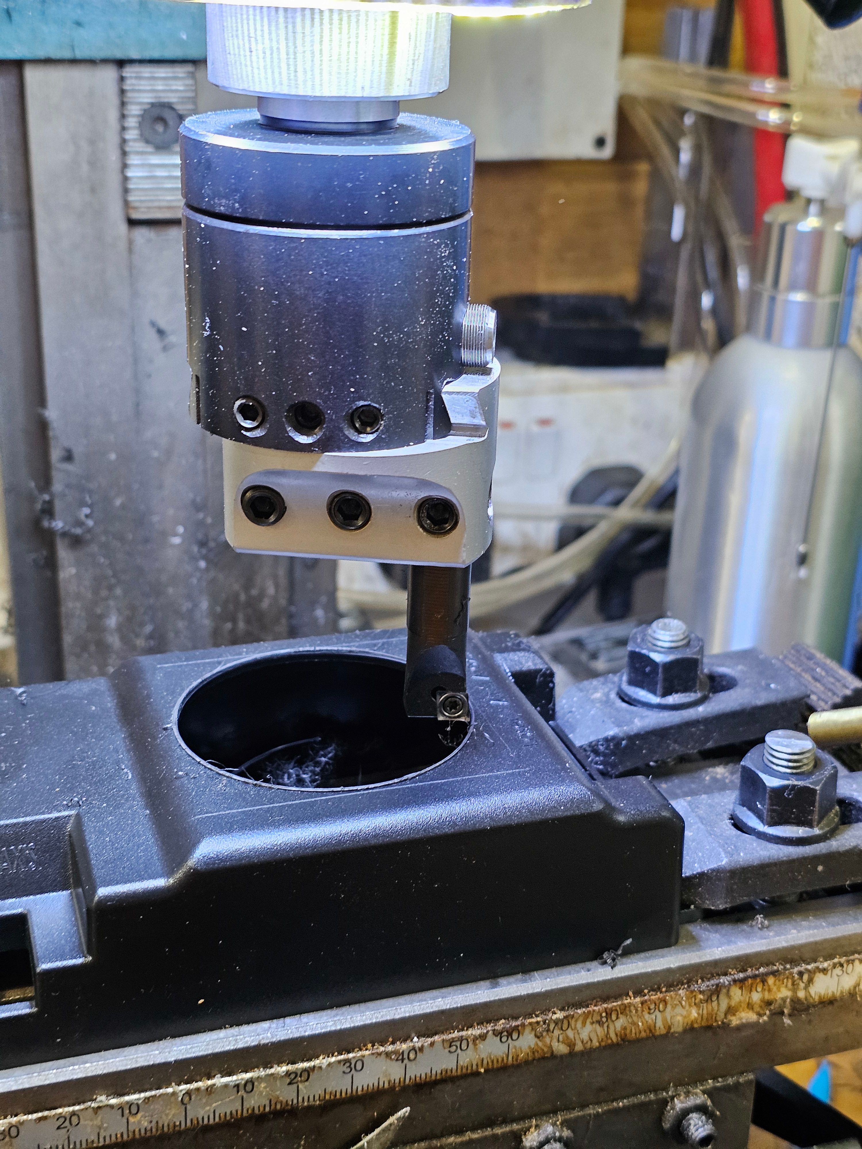
Clockwise from top right: Case with new holes, new fan, old fan, guard, spacer, gasket.
...and assembled.
Got the 2mm silicone o-ring cord delivered. It looks....dirty. I'll try the high-tech fix of warm water and Fairy and see if it comes up to scratch. The whole point was for it to look less visible than black, not look manky!
Silence means that nothing's happening, right? Ah, well you've partially got me. There's a lot been going on with looking for a house to move to, getting gazumped, failing to find anything suitable and generally getting depressed. I've also been waiting for things to sail across the seas.
The o-ring cord came up a bit better after a wash - should be useable at least and there's plenty for trial runs. The spoilboard cutter arrived to surface the fixture plate. What fixture plate? Ah yes, a lot of that I'd been discussing that behind the scenes. LePhuronn originally pointed me at Bit Tech's video of making a fixture plate and it's slowly dawned on me that all the stock screw holes in the bed are in really unhelpful places. So this is the plan for that 20mm thick piece of acetal:
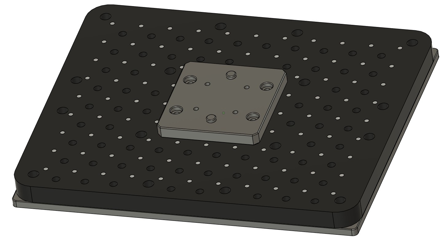
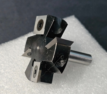
That needs to be flattened and I need to be able to reach the edges of it or slowly end up with a recessed middle and walls round the edge. So a 45mm diameter cutter with a 12mm shank that won't fit in any of the collets I've got as the max is 8mm. Have lathe and stubbornness and hence this now on a 8mm shank:
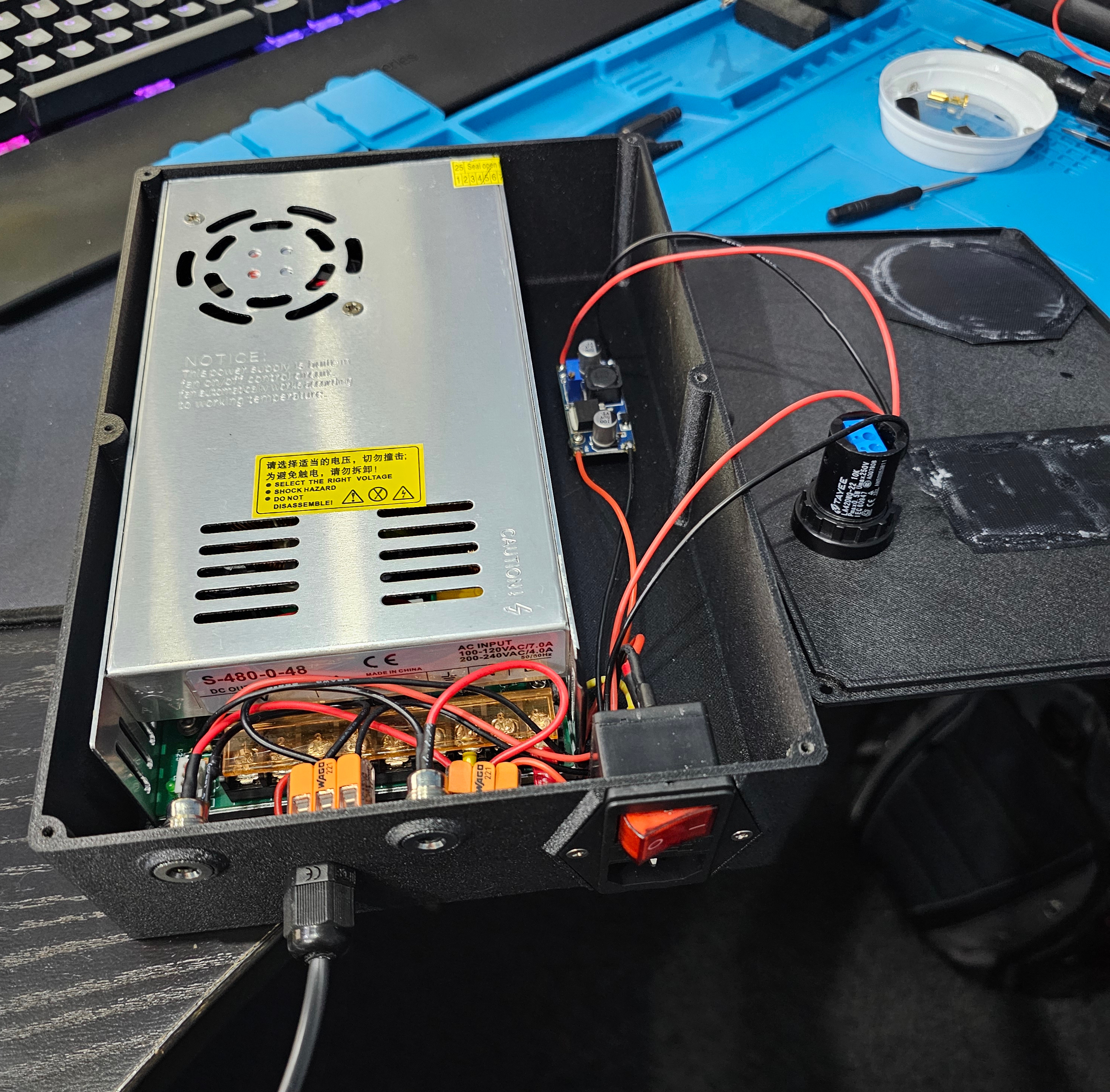
What else. I've been trying to get probes wired up so I can locate work on the bed and also measure the length change or a tool once I change tools. I've mostly got that working using UGS (Universal G-code Sender) which is priced at my favourite price-point....free! I'm now trying to understand some of the other wiring because I want to install a relay to turn on the mains power to the router so I can start and stop it automatically. Why bother? Simply because I well know that at some point I'll forget to turn it on and crash the tool into the workpiece with it not spinning. Blackadder may have said that "We're not at home to Mr Cockup" but unfortunately I'm well aware that I'm not only home but often have the guest room made up ready! Anyway, delving into the PSU box I've discovered a few things:
So rather than try to run a 48V relay to control the mains power to the router and mount that relay outside somewhere, I'm thinking that I can remove the 48V PSU entirely as it does nothing at all for me. That gives me the space inside the box to run a 24V relay for the router and install a C13 socket in the back of the PSU box a bit like PC PSUs of yore used to have to power your monitor.
So why are there four wires to this board and how does speed control work? THAT is a very good question and one that took some serious poking with a multimeter with everything on and a careful attentiveness not to poke any of the mains voltage parts...that are on terminals next to the safer voltages.
The wires in question are: 24V, Relay, VRef and Ground. 24V and ground are exactly as labelled.
'Relay'is held high (24V) is allowed to float to turn off the 48V PSU and pulled low (0V) to turn it on. I suspect the actual relay has a NC connection for the 48V PSU that is disconnected by turning on the relay but it's impossible to trace the circuit without desoldering the relay from the board.
'VRef' varies between 13.5V and 0V and runs through some sort of buck circuit so that it gives an input voltage to the VTR pins on the 48V PSU of between 4.7V and 0V. That causes the PSU to output between 48V and 0V (on what seems to be a 10x multiplier) and that is your speed control. With no input to the VTR pins, the 48V PSU stays off.
Now I just have to work out how to set up a relay so that it's off when there's 24V applied, on when 0V is applied but it doesn't cause the router to turn on unexpectedly when you turn off the controller!
Why do I mention all this? Two reasons: it's a good reference for me when I inevitably forget all this and also, there's a chance this 48V PSU and spindle may find a new home soon....and they may need to run a buck convertor from their 24V PSU to supply enough juice to the PSU to get it to turn on!
Pinout of PSU to Controller:
Edit: Correct information for 'Relay' pin.
The o-ring cord came up a bit better after a wash - should be useable at least and there's plenty for trial runs. The spoilboard cutter arrived to surface the fixture plate. What fixture plate? Ah yes, a lot of that I'd been discussing that behind the scenes. LePhuronn originally pointed me at Bit Tech's video of making a fixture plate and it's slowly dawned on me that all the stock screw holes in the bed are in really unhelpful places. So this is the plan for that 20mm thick piece of acetal:
That needs to be flattened and I need to be able to reach the edges of it or slowly end up with a recessed middle and walls round the edge. So a 45mm diameter cutter with a 12mm shank that won't fit in any of the collets I've got as the max is 8mm. Have lathe and stubbornness and hence this now on a 8mm shank:

What else. I've been trying to get probes wired up so I can locate work on the bed and also measure the length change or a tool once I change tools. I've mostly got that working using UGS (Universal G-code Sender) which is priced at my favourite price-point....free! I'm now trying to understand some of the other wiring because I want to install a relay to turn on the mains power to the router so I can start and stop it automatically. Why bother? Simply because I well know that at some point I'll forget to turn it on and crash the tool into the workpiece with it not spinning. Blackadder may have said that "We're not at home to Mr Cockup" but unfortunately I'm well aware that I'm not only home but often have the guest room made up ready! Anyway, delving into the PSU box I've discovered a few things:
- There's a 24V PSU to run the control board, the stepper motors and the screen.
- There's a 48V PSU to run....just the spindle I'm not actually using.
- There's a "3040 Max relay signal board V1" with four wires running back to the control board.
- Some of the 'fan' noise is actually stepper whine when the hold current is applied.
So rather than try to run a 48V relay to control the mains power to the router and mount that relay outside somewhere, I'm thinking that I can remove the 48V PSU entirely as it does nothing at all for me. That gives me the space inside the box to run a 24V relay for the router and install a C13 socket in the back of the PSU box a bit like PC PSUs of yore used to have to power your monitor.
So why are there four wires to this board and how does speed control work? THAT is a very good question and one that took some serious poking with a multimeter with everything on and a careful attentiveness not to poke any of the mains voltage parts...that are on terminals next to the safer voltages.
The wires in question are: 24V, Relay, VRef and Ground. 24V and ground are exactly as labelled.
'Relay'
'VRef' varies between 13.5V and 0V and runs through some sort of buck circuit so that it gives an input voltage to the VTR pins on the 48V PSU of between 4.7V and 0V. That causes the PSU to output between 48V and 0V (on what seems to be a 10x multiplier) and that is your speed control. With no input to the VTR pins, the 48V PSU stays off.
Now I just have to work out how to set up a relay so that it's off when there's 24V applied, on when 0V is applied but it doesn't cause the router to turn on unexpectedly when you turn off the controller!
Why do I mention all this? Two reasons: it's a good reference for me when I inevitably forget all this and also, there's a chance this 48V PSU and spindle may find a new home soon....and they may need to run a buck convertor from their 24V PSU to supply enough juice to the PSU to get it to turn on!
Pinout of PSU to Controller:
| PSU end (green connector) | Wire colour | Function | Control board end (white connector) |
| 1 | Red | 48V+ | 1 |
| 2 | Green | 48V- | 5 |
| 3 | Orange | 24V- | 6 |
| 4 | Black | 24V+ | 2 |
| 5 | Blue | 24V (back to relay board) | 7 |
| 6 | Yellow | 'Relay' (back to relay board) | 3 |
| 7 | White | 'VRef' (back to relay board) | 4 |
| 8 | Brown | Ground (back to relay board) | 8 |
Edit: Correct information for 'Relay' pin.
Last edited:
Ok, the 48V PSU is now out and I've got an AC outlet (C13) on the back of the box now. Relay works so I just need to mount that, wire it and put it all back together.
The spares are now put together ready to pair with another CNC's 24V PSU. Case is done, speed control is done, buck convertor done, all the power inlets done....and suddenly I realise I've not designed in any way of getting wiring OUT to run the motor. *sigh* So the walls of the box are solid and also of PETG-GF so maybe I can drill a hole in it without it fraying like you get when you hit infill. Yup. Installed a small IP-rated gland to solve that and added a switch (the rotary one) as it dawned on me that there wasn't a convenient way of turning it off - it would switch off when the 24V PSU was off but the only isolation was to pull the lead....and now I think about it, the spindle would be running the entire time the CNC was switched on *facepalm*
Here's the result:
I also found out after doing all this that the 24V PSU isn't on a 5.5mm/2.1mm barrel jack, it's on a 5.5/2.5mm barrel jack....so the jacks in this are scrap. So parts ordered and may have to redesign and re-print the box. Also ordered some (hopefully!) better crimps as I discovered that mine suck and leave the connector nicely loose on the wire. Just what you want for mains voltage connections, right?! Don't worry, I didn't leave them like that I stripped off the insulation and crimped them properly and then heatshrink'ed them. Back to the drawing board then. Might be able to make it less of a pain to assemble for next time!
The spares are now put together ready to pair with another CNC's 24V PSU. Case is done, speed control is done, buck convertor done, all the power inlets done....and suddenly I realise I've not designed in any way of getting wiring OUT to run the motor. *sigh* So the walls of the box are solid and also of PETG-GF so maybe I can drill a hole in it without it fraying like you get when you hit infill. Yup. Installed a small IP-rated gland to solve that and added a switch (the rotary one) as it dawned on me that there wasn't a convenient way of turning it off - it would switch off when the 24V PSU was off but the only isolation was to pull the lead....and now I think about it, the spindle would be running the entire time the CNC was switched on *facepalm*
Here's the result:
I also found out after doing all this that the 24V PSU isn't on a 5.5mm/2.1mm barrel jack, it's on a 5.5/2.5mm barrel jack....so the jacks in this are scrap. So parts ordered and may have to redesign and re-print the box. Also ordered some (hopefully!) better crimps as I discovered that mine suck and leave the connector nicely loose on the wire. Just what you want for mains voltage connections, right?!
Don't worry, I didn't leave them like that I stripped off the insulation and crimped them properly and then heatshrink'ed them. Back to the drawing board then. Might be able to make it less of a pain to assemble for next time!Got my PSU box reassembled now. Need to test it but it should allow me to turn the mains-powered spindle on and off with G Code.
Got new parts for the other PSU box. Had to redesign the box and it's currently printing off. Stuck filter mesh to the intake and outlet with mitrefast (superglue and activator) but last time I got it on my fingers and had to sand it off, so this time I'd obviously learned my lesson and wore gloves....and instead I was gloved and glued to the mesh.
Trying to make some progress on other parts but a lot of time and sanity is being taken up looking for a new house and being either depressed (lack of properties that tick the boxes in the price range) or messed about on offers. Hoping to end up with somewhere to put the CNC so I can actually use it!
OK, Take 2! ...now with on/off switch and jacks that are actually the correct size!

Not content with supergluing myself to things, I discovered that if you have the spindle on the floor and start it up at full pelt, the torque makes it jump about. If you then try to grab it, the 'fan' part at the top slices neatly into your fourth finger *facepalm*
Not content with supergluing myself to things, I discovered that if you have the spindle on the floor and start it up at full pelt, the torque makes it jump about. If you then try to grab it, the 'fan' part at the top slices neatly into your fourth finger *facepalm*
Last edited:
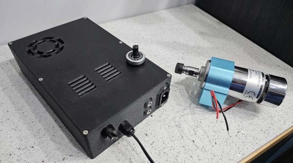
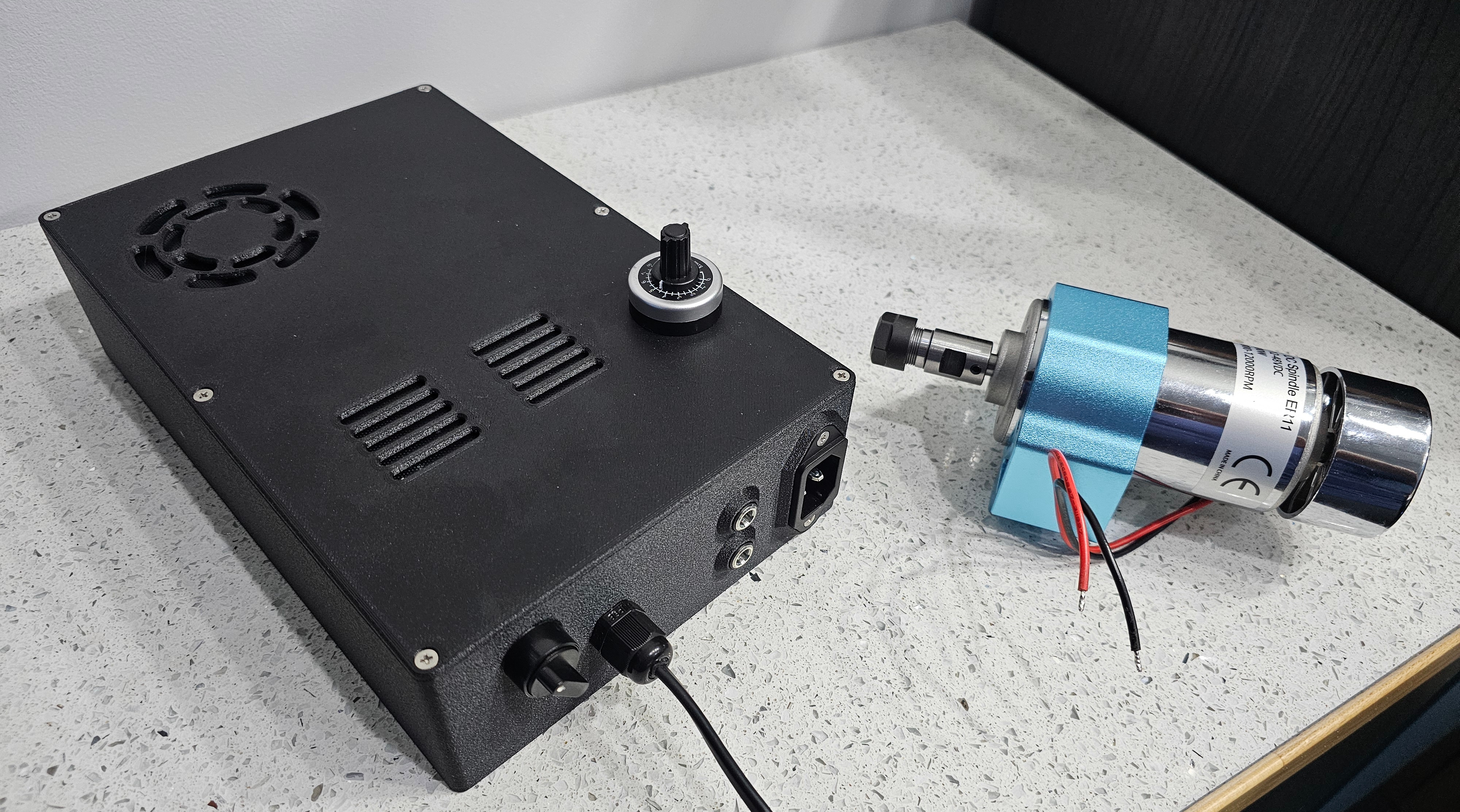
Yes....this is the donor kit. PSU is variable output and doesn't output any voltage unless you feed it a control voltage (0-5V). That's what the 24V input is for (from the control board PSU) and the buck convertor to bring that down to 5V and 10k pot to vary it from 0V to 5V so that the spindle runs from 0-12k rpm.
a lot of time and sanity is being taken up looking for a new house and being either depressed (lack of properties that tick the boxes in the price range) or messed about on offers. Hoping to end up with somewhere to put the CNC so I can actually use it!
Well, at the risk of jinxing it (the legal stuff's going through currently) this shall be my new workshop:
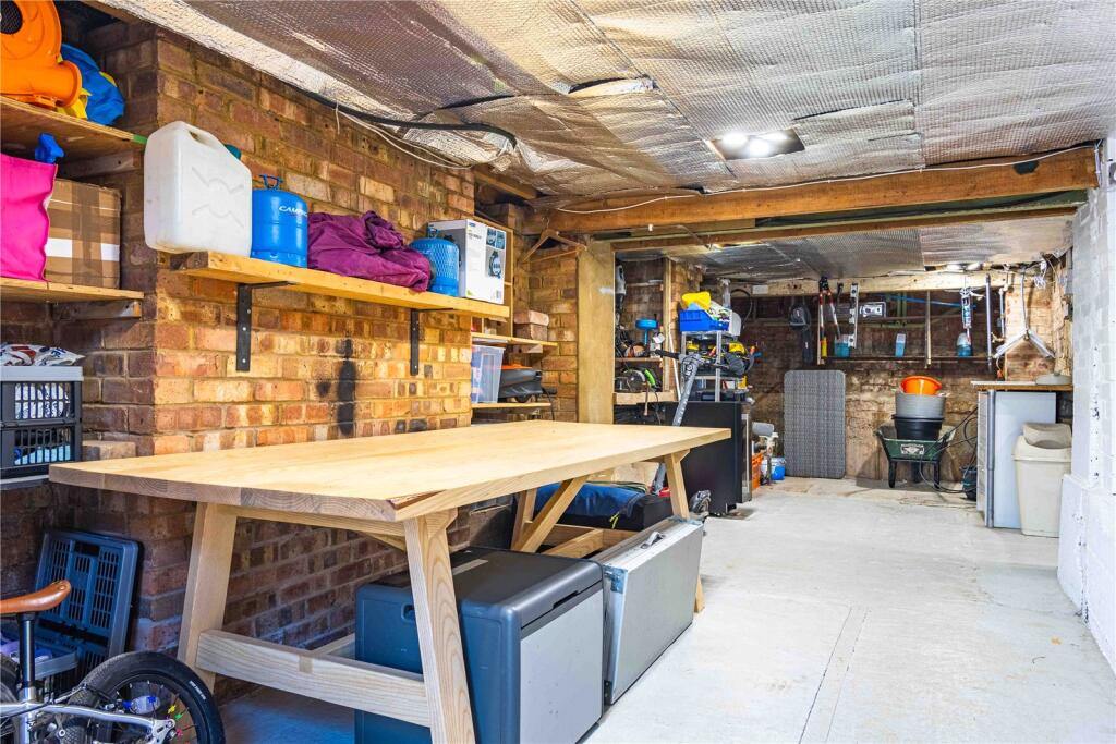
Needs a few niceties like a ceiling and more lights (I know, I'm a fuss-arse!) but it's quite a bit more space. May have to see about heating too!
I suspect there may be very limited progress until I get settled in to the new place - what with packing and moving and unpacking again.
I joke. TBH Gary has more time and faster machines tbh.
Don't blame you on not moving again, but you probably will when you retire. It's a massive pain tbh. I know people who like to move a lot, never did understand what sort of S&M it was !
Don't blame you on not moving again, but you probably will when you retire. It's a massive pain tbh. I know people who like to move a lot, never did understand what sort of S&M it was !
My house move was a disaster, I have zero intention of doing it ever again.
Although it's now been almost one exact month since I finished it, maybe I should start unpacking now...
I’ve still got 3 boxes in the eaves I never unpacked. So I’ve only been here 7 years lmao
Well, at the risk of jinxing it ...
Damn me and my big flappy face-hole!
