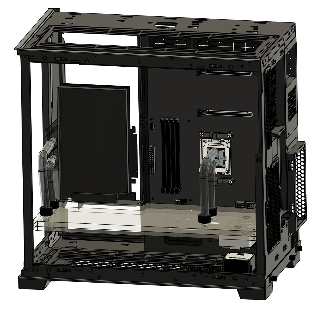
Project: Silent Overkill

PETG is even more hygroscopic (reason #2839 to not use that junk in a hardline loop) so I fear you'd end up in the same boat.

Honestly, FDM printing is likely a dead end for a final product simply because the layers are never a 100% cohesive mass. Now, you can get post-processing materials to add coatings and whatnot and maybe you could form a seal (at least an external skin) that way.

It sounds like your prototypes are functionally sound though. Question is, do you want to drop £400 on an M70x2 tap and die set :P
 
Hah, you reckon it'd be that cheap?! Hang on, curiosity.... first hit is £986.12 +£12.50 delivery....but there is one for JUST £333.79 with free delivery...and it's in HSS! :D ;)
You probably have to single-point it anyway; the lead-in would probably be the better part of half a metre!
Anyway, you're not thinking like a man with just a hammer...you make the part touching the coolant out of delrin, leave a flange and make the two clamping threaded parts that don't touch the coolant on the 3D printer. Simples :D
Since I've printed a pair now, I'll see how much air pressure (or how little!) it'll hold before an end cap blows off, for giggles....and then worry about it if it even fits the plan*.

I did have fun modeling up the GPU and how it fits in the block I'd previously modeled. Ideally need the GPU in one hand and Fusion in the other. Onboard GFX to the rescue! Can now position it in the model though and that lets me put the ports in the right place etc. The bends are easy...in CAD! Although saying that made me realise I can't have two bends in a tube if I want them to be glass *facepalm*

*All references to a 'plan' are for brevity only and do not in any way infer or imply an actual clue as to how things will pan out :D
 
Delrin component for the coolant contact areas sounds like a plan, the glass fibre PETG should have enough strength to support it all.

Can't have two bends in a glass tube? Sounds like a man without a blowtorch and blow hose...
 
Last edited:
Half right. I'm a man who dangerously wields a blowtorch, not really appreciating how quickly it'll get something not to softening temperature but to puddle temperature. The glass is borosilicate though so softening temp is either 820°C or 1200°C depending which figure is applicable. It's also 16/11mm so getting a nice bend in it at home is likely to be near impossible - a rough by-hand blowtorch bend has been done by JZ Two Cents on YouTube I believe but I think I'm better to just plan the loop to only need the single pre-bent 90°s you can buy.

I'll be honest, the only reason I'm looking at tube res's is because it'd be a convenient place to put a LeakShield...and I rather fancy the new toy :D
 
Might for giggles put a pressure test on it
Well, giggles yes...but probably the unsurprising kind. There is, of course, a reason why nobody else is doing it this way! Pressure tester got to a whole 1.5 psi (about 0.1bar) before it blew the top off with a POP. Always the smaller end; the other stays on better - in fact it's quite difficult to pull it off. I suspect one end flares a little so you could maybe do this if you were able to shape the glass. Did also test it with a pressure relief membrane to see if it would be useable that way....nope. Top pops before the membrane opens. Ah well, the drawing board beckons.
 
Now I've got more in to Fusion and also manufacturing is so much more available, I've gone and started watching videos on the sorts of dimensions that might be required and how I might integrate the pump tops into it.

Shout if you need a hand with anything.

Well, funny you should say that! Was just digging about and stumbled up this Custom DDC Pump Top Design and who should it be by? :D
Was wondering how you got on with the shape of the volute and the positioning of the outlet? Like you, I've seen plenty that are just circular but I'm led to believe that some sort of spiral is preferable for performance. I'm looking at the XSPC tops and they're definitely not circular.
Inlet is about 10mm but restricted just before entry to 7.5mm - given that's a glued on piece, I suspect it's important.
Outlet is 7.4mm angled upwards 10° but I can't tell if that's just for ease of manufacture (it's a single block, not two layers) or important for performance. I suspect it's just to raise the G1/4 hole high enough that there's space round it for an o-ring to seal.
I've also got to chain two of these together.....can't go backwards in spec!
I have the luxury (in theory) of CNC to do this rather than a drill press. It should be comedy and there will definitely be pictures! Why comedy? Well, what I have access to is a CNC router for wood...but it should handle acrylic....and the bed is about 12 foot long! We shall have to see how it handles tiny o-ring grooves near an edge!
What did you find out about the importance of the shape of the volute and position of the outlet?
 
It was actually a pre-EKWB Joe Robey (JR23) who chimed in on that thread you linked when I was planning to just hack at a chunk of Acetal with some Forstner bits. The images he linked died very quickly but they showed how the spiral forms between minimum and maximum radius, and I just copied it Illustrator as a basis (I was only just starting out with Fusion at the time).

He didn't actually explain why, but I would presume it'll be about increasing centrifugal force and therefore exit velocity at a lower RPM (plenty of stuff online about spiral volute fans). Besides, when a well respected and prolific modder at that time rocks up to your pre-planning log and says "it's best done this way" you tend not to argue and just do what he says :P

There was nothing special about the position of the outlet, other than it's at the maximum radius for the spiral, and of course in the direction of the water flow. Any angle I put on the outlet channel would've been to maximise the amount of material for walls and such in the limited confines of the pump top (I 100% had to keep it 20mm tall in order to fit the build).

Now, the pictures are dead in that thread so it's actually of an older design that was still square to match the DDC body size. You'll see in the Asteria II log proper that I extended the size of the pump top and completely reworked the inlet and outlet as a result (milled out pockets instead of tubes and then sealed with a single steel top plate, just like Aquacomputer did with their multi-port top I used as inspiration). The volute shape is still the same though.

You want me to see if the older files are still around and send you some drawings or Fusion for the volute shape?

As for your CNC, if you can cut acrylic then you can cut Delrin/Acteal, but it can get gummy in a hurry and doesn't like super fast tooling.
 
Last edited:
Definitely, if you've got them. All input is good to be blunt.
I've turned Delrin and it does so very nicely.... doesn't break a chip though (at the sort of parameters I can manage, at least) so you end up with a long string being pulled off....or worse, wrapping itself at high speed round the part and whipping about. Can imagine how that could be problematic if you take away the nice exit route and instead hem it in, in a trench! Thing is, Delrin as great as it is, would look rubbish for a distro plate....unless it's some sort of stealth build!

First port of call is to 3D print it anyway. Yeah, I've proved it's a terrible idea for a production part but for dry prototypes, it should be a lot easier than trashing acrylic in someone else's workshop out of hours!
 
Oh, you're putting the DDC into the distro. Gotcha.

I'll see if I can dig out some bits for you then, should be on a hard drive somewhere. At the very least I should have the V1 DDC top on Fusion, and I still have the extended Asteria II top for sure. The Fusion models should give you an idea of what I did and have editable sketches and whatnot.
 
That's the plan (that term still feels wrong! :D). Except obviously two of them in series, just to make it more complicated!
Was originally thinking to incorporate a strainer like the Aqua Computer one but it seems quite restrictive so now since the rad is going to be external in QDCs, I'm thinking that it could be an inline filter somewhere in that chain of QDCs so it can be removed for cleaning without draining. A genius idea if one could but buy the right QDCs!
 
Here you go, preliminary ideas complete with 'impossible' double bends to the GPU :D

LianLiEvo6.jpg


Hmmm, might need a gnat's more clearance for those 12V ATX connectors :D
 
Last edited:
If you're building your own vertical mount for the GPU anyway then you can shove the GPU anywhere you want to line up those tubes better and get rid of the horizontal kink.
 
I've got the upright mount from Lian-Li but I've not committed to the £86 PCIE cable yet :D So horizontal alignment is a bit fixed.
Might be able to shunt the block ports across a little but my initial layout of the base block was done with the idea of mounting it on the fan/rad bracket so it would need to slide to clip in. That limits the size a bit at the front. But if it comes to it, I could even drill my own holes :eek:

I've also since realised that I need to raise the block up (as can be seen in the pic) because I'll need to fit stuff under it - the pumps at a bare minimum! I'm thinking I might restrict the loop to the front section of the case and have the loop exit the case (to/from external rad) where the flow meter is in that pic. Have found that Alphacool Eiszapfen QDCs are available as bulkhead style. Might sort out the lack of availability of the Koolance ones. Not sure they have 16/10 versions though so would either have to be a chain - not ideal for compactness - or hope that Koolance and Alphacool fittings are compatible. They LOOK the same but what are the chances!?
 
That looks mad!

Cheers. No, "mad" is self-designing it and self-making it. Not so much perhaps if you've done it before but... let's say there's going to be a lot more colourful language before we're through!
Worse case I can farm out the manufacturing to a Chinese fab but I definitely want to have a go at loading a (friend's company's) 12’ CNC wood router with some tiny endmills* and setting it at a lump of acrylic. Being aimed at wood, it might have the spindle speed to not snap them as soon as they touch the workpiece!

*Autocorrect thinks I mean windmills....I assure you, I don't! :rolleyes:
 
Found a load of the old deign files for the spiral volute. Trying to rebuild them as dimensioned sketches in Fusion so they're more usable. Inner circle diameter is 41mm, outer circle diameter is 46mm, spiral between the two. Will give you a nudge when I have something.
 
Last edited:
Back
Top Bottom