Random 3D printing chatter

Soldato
OP
Joined
4 Jun 2007
Posts
2,632
Location
Watford, UK
Just check it doesn't have upgraded springs already. I just bought an Ender 5 Pro and it seems to have them already - they're orange/yellow instead of silver and quite stiff. Not certain these are the same or if they've bothered to apply the same to the 3 Pro but just a heads-up as I've already bought a silicone sock (that a guide said I needed) for mine only to find it already had one :rolleyes:
 
Soldato
OP
Joined
4 Jun 2007
Posts
2,632
Location
Watford, UK
The heathen (for this forum) in me is saying just drill two holes in a spare one. You may want a smidge more clearance than 0.2mm purely as things will move and expand and you don't really want it dragging on your tubing and either damaging it or pulling it out.

Progress on mine involved cutting a 92mm fan hole. Panel too big to swing on the lathe, too big to spin on a rotary table (would hit the column) and too big for my boring head on the mill. So the vintage adjustable hole cutter it was. Worked but its kind of terrifying spinning round that wide and my mill doesn't have the torque to run it any slower. Looks good though....for the bottom where it'll never be seen!
 
Soldato
OP
Joined
4 Jun 2007
Posts
2,632
Location
Watford, UK
Progress so far (click for larger image). I'll be shortening the wires from the buck convertors to the PSU, they were left long until I'd decided where to place everything. The Creality control board is going to be shunted further up towards the top left corner. That'll allow the display connector to clear (hopefully!) the fan blades....but it's going to be down to a mm. I'll probably have to mill down the last factory mounting post you can see there so it doesn't risk shorting out the board. Might be able to mask it off, not sure yet. The other three have custom 3mm thick washers made up so they can be used to screw the base plate into the box. Had I thought about this beforehand, I'd have left a tab on the far right of the base plate so I could screw that end down with one of the PSU screws. I think that some form of double-sided tape may fix this oversight without needing additional holes in the top of the case though. Sometimes the call of the path of least resistance is too strong!

The base plate is from an old Cooler Master case - it's 1mm aluminium plate. Just means that I've not had to drill holes in the top (once mounted in the printer upside down) of the case so I can change my mind at worst. All the boards are up on standoffs. The Pi is on 6mm M2.5 standoffs (Pi mounting holes are M2.5 rather than the more common M3), the Buck convertors are on 10mm M2.5 standoffs because there were a limited number of the 6mm's in the kit and I didn't want to buy a bag of 100! The Creality control board will be on 6mm standoffs but I'm going to have to mill them down to 4mm (like the original factory ones) or find out which wins of plastic fan blade vs ribbon cable connector!

I'll have to blank off the extra fan hole - I'll be honest, I'm thinking that duct tape will do the job here. I'll also blank off the vent on the left edge so the air should then be forced to travel over things and exit on the far right and the top vent - otherwise it'll mostly just leave via the nearest exit without cooling anything. I plan to leave the lid off the PSU too - I don't think there's an EMI issue as there's still a metal wall between it and the control boards and there's still grounded metal surrounding it and preventing finger ingress.

I also have a small LED-illuminated tactile switch that I'm going to mount on the front edge of the case. That will light up when OctoPrint is ready to go and shut down the Pi when pressed. That's this GPIO Shutdown plugin. I just need a fragment of PCB (or something rigid and heatproof) to mount the switch in and clamp it to the front panel.

USB header is going to go in the bottom right corner to plug in the obligatory webcam. No doubt an ethernet header will have to join it when I find out that putting a Pi in a grounded metal box results in no wifi reception! We shall see though.

 
Soldato
OP
Joined
4 Jun 2007
Posts
2,632
Location
Watford, UK
Afternoon all. Some progress, some to go and some issues.

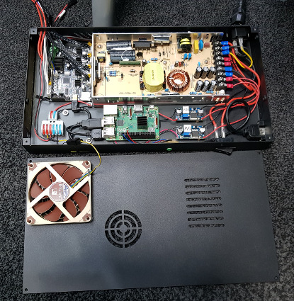
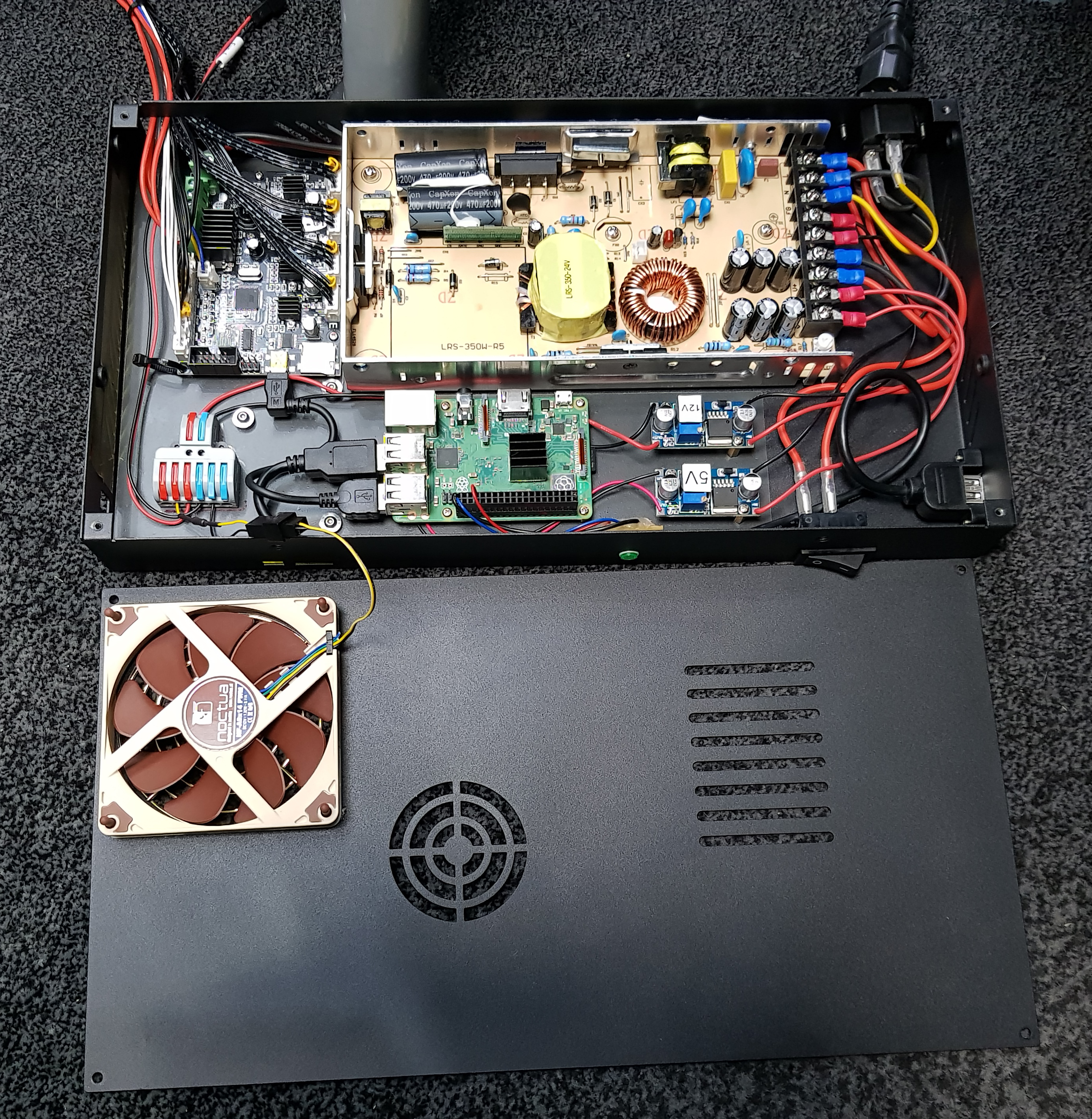
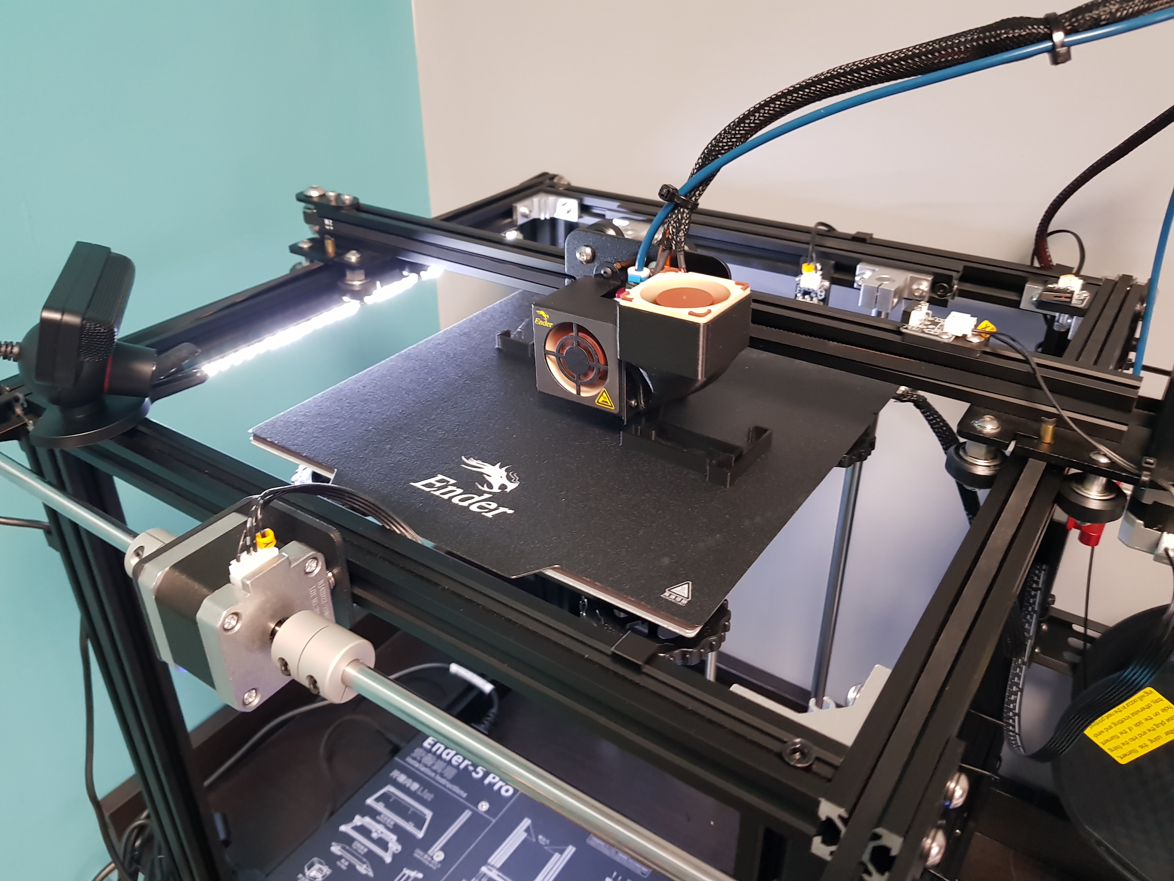
I needed things to be quieter or I wasn't going to be able to use the printer much - wife shares the same office and is now full time. So far we have a Noctua 40x20 as the hotend fan. That's currently got just a couple of M3 standoff nuts holding the cowl further out since it's twice as thick as the stock fan. Went with the thicker one as it was quieter and had higher static pressure. PSU fan (60mm) and control board fan (40mm) are now gone and replaced by a 92x14 Noctua. Went 92mm simply because that was the only one thinner than the 25mm standard....and I was pushed for space as it was! Some of the factory vent holes at the sides have been blocked with Kapton tape and the 60mm fan hole in the lid has been block with some lovely black duct tape - classy! This should mean that the 92mm fan blows air over everything though. I fitted the low-noise adapter (you can see the inline resistor that's left after I stripped it down) and that does mean it's pretty much silent. I can feel an outdraft of air from the vents that are open so hopefully it's all good.

I still need to sort out the layer fan as that's horrible. The bearing is.....bad and the PWM done by the control board is noisy. Can't do much about that until I'm able to print a duct to allow an axial fan to replace the existing radial blower.

So, a mounting board for all the stuff so that I wasn't making ugly holes in the top of the case - mainly gave me the ability for a do-over if necessary. The new base plate used to be the side panel for an aluminium Cooler Master case and it's 1mm thick. Modelled out the insides to make sure everything would fit. Used transfer punches to mark out and then drilled 2.3mm holes in it. Then tapped those with an M2.5 roll tap. These form the threads by displacing the metal rather than cutting it. Apart from the bonus they don't make any chips (not so relevant in this but very useful in blind holes) they also seem to do a better job in very thin sheet materials like this. M2.5 simply because that's what the Pi is pre-drilled for - in hindsight it probably would have been more sensible to just enlarge those holes as the hex of the standoffs is the same size anyway. Ah, you live and learn....well, hopefully.


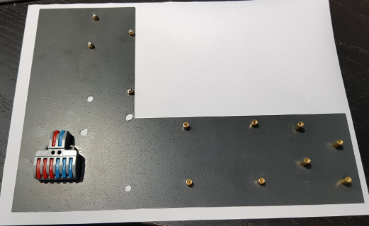
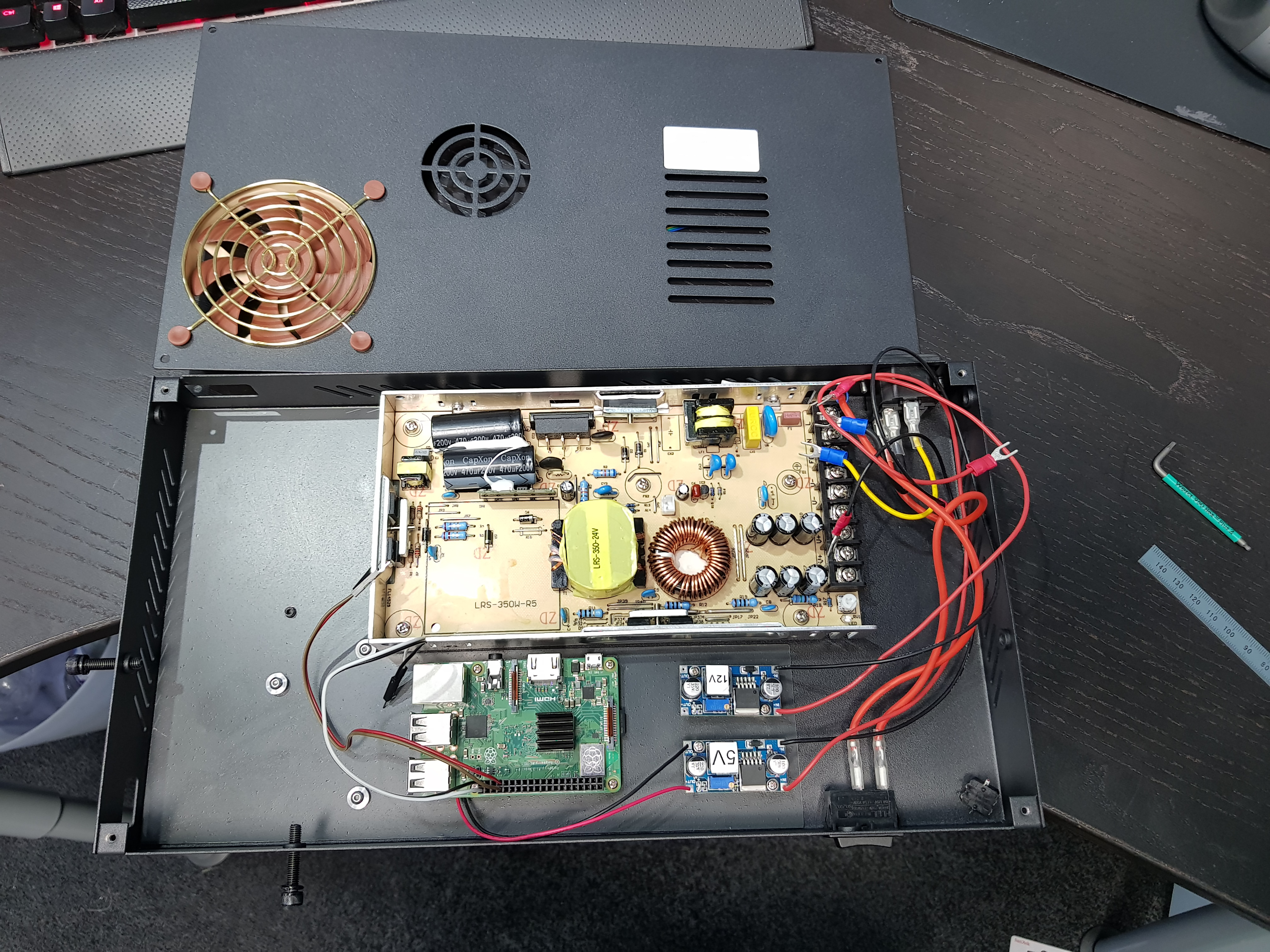
The lever block (SPL-62 Wago-style) is for distribution of 12V. The convertors are LM2596S buck convertors at five for £9 online. One for 12V for the fans and one at 5V to power the Pi. I soldered wires to the points on the bottom for this because I wanted the protection of the polyfuse on the microUSB port (which is bypassed if you feed the header pins directly) but didn't have room for an actual microUSB plug. The Pi is connected to the USB of the control board so I can load prints via OctoPrint.
The USB on the right is for the webcam. I went with a Playstation 3 EyeToy because it was a tenner all-in (and on the supported list)....but mainly 'cos it was cheap :D
The green LED you can see on the front is an illuminated tactile switch. Using GPIO Shutdown to light up when Octoprint is ready and a press of it shuts the Pi down before power-off. I found some copper-clad PCB, drilled the through-holes for the switch's 6 pins and milled the copper off to leave pads to solder to as well as a track to the resistor. The whole thing is friction fit into the 8.2mm hole drilled in the case - step drill essential here or it'll end up triangular and followed up with the 8.2mm after getting to 8mm.

So it's all good now, right? Yeah, you'd think. I wiped down the bed with IPA and levelled it. Started printing a 20mm calibration cube. Got 4mm up it and it left the bed. Good news is that The Spaghetti Detective worked and stopped the print. I was there but left it failing for a bit to test whether TSD worked. I suspect if you pay for the premium version it'll spot the fail earlier as it samples more frames than the freebie.

Re-levelled and had a few goes at printing a hollow cube and got problems. Those turned out to be Cura settings issues with thin walls and I eventually got that printed. It does look like I have adhesion issues though. The nozzle prime down the right hand edge sticks very nicely but the actual print right in the middle, does not. I checked all the corners were level - a sheet of A4 drags - and then checked the middle of the bed. It took three sheets stacked to get a light drag. Is this the infamous Creality bowed bed issue?
 
Soldato
OP
Joined
4 Jun 2007
Posts
2,632
Location
Watford, UK
Is it a Fat Man missile and/or launcher from Fallout? Took me a minute if so!

I just printed some clips that clip into the bottom of a 2020 extrusion and hold a strip of waterproof 3528 LEDs ('cos that's what I had) so I don't have to leave the lights on when printing. Only took me 6 iterations before the strip fitted the slot! :rolleyes:
 
Soldato
OP
Joined
4 Jun 2007
Posts
2,632
Location
Watford, UK
1.5mm layer height? I'm a noob so forgive me if I'm not sure whether that's a typo or just my ignorance. I'm used to a layer height being more like 0.2mm. Are we talking bigger nozzle diameters here?
 
Soldato
OP
Joined
4 Jun 2007
Posts
2,632
Location
Watford, UK
Not a problem, just wasn't sure if I was more clueless than I was aware! :D
Looks good by the way.

Having bought an Ender 5 Pro on the grounds that I wanted to be able to use it and didn't want to be replacing parts of it straight away or printing upgrades to it.....I've dismantled, modded and upgraded it.

The fans in the control box I changed already but now I've done the hot end fans too. The joy, of course, being to make sure that the duct doesn't crash if the head moves full scale.
I've also made and printed some brackets to hold that light strip you can see - they just clip into the bottom slot of the 2020 extrusion - and I've added a toggle switch to turn on/off a jack socket that feeds them off the same 12V buck convertor that runs the fans.

The layer fan isn't totally quiet but that's mainly due to the fact that it's running off a really poor PWM implementation. I believe I could turn up the frequency of the PWM by modding the firmware.....but I'm not sure I'm there yet! It's a lot quieter than it was already.

The other thing that may not be obvious is that I've rebuilt it bass ackwards. This allows the Y-axis motor to be at the front instead of the back. Flipping it means that 0,0 is still in the back right corner. This means I can push it back far enough that it will fit on the work surface (39.5cm deep - nominally 40) without the front feet falling off the front. Previously I had to have a couple of planks under the feet to extend the surface....not the best of looks!

Web cam is now also mounted on a 4mm shaft that fits in the corner bracket much like the Y-axis stop does.

 
Soldato
OP
Joined
4 Jun 2007
Posts
2,632
Location
Watford, UK
Cheers. Since you seem to be diagnosing print issues, would you care to comment on one of mine please? The first support I printed upright at 150mm long with the intention of joining two of them to span the 300mm length. As you can see, it wobbles somewhat towards the end and that scrapped it because I couldn't slide the LED strip in. I 'foxed' the problem by printing three runs of 100mm instead but wouldn't mind knowing what the issue is called and maybe how to fix it. I was thinking it looked like lost steps but it would seem odd that it conveniently lost them in the other direction to bring it back again. The three 100mm sections all printed fine.


Soldato
OP
Joined
4 Jun 2007
Posts
2,632
Location
Watford, UK
I printed it with the length of it straight upwards. Mainly because I wanted the layer lines of the end clips to run in the direction that they would spring rather than the movement pull the layers apart but also I thought it would work and look better. So the movement is sideways rather than downwards. There was support printed between the two clips.
I definitely had issues with the rollers on the extrusion. There were definite detents as you rolled it by hand. I initially thought it was dents/chips/flatspots on the wheels but when I tested it rolling it up and down a short length of extrusion (while I had the top frame apart) I found it stuck slightly on an imperfection in the extrusion. I can't find any on the actual lengths that the Y axis runs on and the effect seems to have gone. Actually that may be a lie as I found some again. It seems to go with cleaning but I suspect it comes back again so there's definitely an issue.

I've retensioned the Y-axis belts as part of rebuilding the top frame. They're slightly tighter than the factory-set X-axis. How tight should they be set?

In terms of wheels on the Y-axis, there are four on each extrusion. I've just checked them and on the left side, the outer wheels will spin with axis still - one very easily and one with just a little resistance. This, I suspect is not a good sign. On the right side, one will free spin. The inner wheels have a hex shank and the outer a round shank so presumably the inner are adjustable by loosening the top screw and then rotating the hex and the outer not adjustable?
 
Soldato
OP
Joined
4 Jun 2007
Posts
2,632
Location
Watford, UK
That's true, but I bet you have a better working knowledge of it already......less sanity left, perhaps, but all things have a price! :D
Part of me wanted to shove an Aquaero in mine so I could tell if I'd got temperature issues after I totally re-jigged the control box (and hence PSU) cooling. I can tell the Pi 3b+ is staying under 40°C though so I think it's all good.
 
Soldato
OP
Joined
4 Jun 2007
Posts
2,632
Location
Watford, UK
The one tip I can offer is to make sure your electronics box is accessible. Mine is, I think, partly structural in that it stiffens the frame. It's also mounted upside down - presumably to keep falling things out. All the wires have joiners half way along them so that it's easy to put together out the box. Trouble is, the slightest problem (I'm looking at the Pi not booting or not playing nicely on the wifi here) and you have to cut all the cable ties to disconnect the cables, unscrew the box from the frame, flip it upside down and unscrew the lid. At a bare minimum, it would be preferable to be able to unplug the box without having to cut all the ties - although I've been replacing a lot of them with printed clips. Failing that, an HDMI and USB port mounted on the case would be another option so you can get to the console of the Pi. Access to the SD card would have been another good plan.
 
Soldato
OP
Joined
4 Jun 2007
Posts
2,632
Location
Watford, UK
Agreed but at least visually, the CR-6 looks to be in a different class to the Enders. Be interesting to know if it's just appearances.

@Rilot That CNC is clearly subtractive machining and therefore not at home in an additive forum ;) :p Looks good though. Hefty linear rail on the back there. Is it limited to Aluminium by the spindle or can it handle steel? I'd have guessed by the size of the rail that with the right spindle it could handle something tougher.

@Vince Sorry, missed out on notifications for a couple of pages worth. Mini Nuke is looking nice.

@ChrisLX200 Had my printer in bits again but have had a go at adjusting the wheels. Seems the inner wheels are adjustable and the outer not but I think the whole plate is on slots so loosening the screws adjusting and then tightening them seems to have allowed me to get a reasonable balance....I hope. Proof will be in the printing but spent all my time swearing at inanimate objects in an entirely sane fashion :D

OctoPi networking issue. I took everything (the control box, specifically) apart again.....and again....and again - hence the swearing - because I had issues with the Pi running OctoPrint. It stopped connecting to my wifi on at least half the boots if not more. Then found it wasn't pingable reliably but I could SSH into it and the web interface was working. All very odd and I put it down to wifi being as reliable as your average plumber (apologies to any plumbers reading, if you're offended you're clearly above average :D) and also that the Pi was shut inside a steel box.....which obviously is great for signal propagation! Ordered a panel-mount ethernet port and have shoe-horned that into the case too. This was going to fix the problem. Tested it, all fine. Put it together, nope. After much faffing about (Pi has to be unmounted to get an HDMI cable in), I found that sometimes when it boots dhcpcd reports "eth0: waiting for carrier" and then "Timed out". "Fixed" this by setting a static IP and testing it worked. Put it all back together and it decided it wasn't going to stay working. You can see why there was swearing, right? Anyway, it seems that sometimes it correctly initialises networking and sometimes it doesn't. If it does, it works fine. If it doesn't then restarting dhcpcd or downing the interface (ifconfig eth0 down) and bringing it up again make no difference. I don't know why it happens but I do have a badly-implemented workaround that perhaps some of you can improve and at worst it might spare someone the diagnostic phase if they have the same problem.

This is the thread I found: https://www.raspberrypi.org/forums/viewtopic.php?t=269898
My workaround is to add "ethtool -s eth0 autoneg on" to /etc/rc.local both before and after the octoprint stuff - just adding it before didn't seem to work 100% of the time - like I said, this is a badly-implemented workaround and almost certainly in the wrong place. The same could probably be done for wlan0 but perhaps a different command - any successful ethtool command seems to bring it to life. Incidently, I tried reflashing the SD card with a new copy of OctoPi and it did the same. I've also tried apt-get upgrades, full-upgrade and dist-upgrade as well as uninstalling and reinstalling dhcpcd5.
 
Soldato
OP
Joined
4 Jun 2007
Posts
2,632
Location
Watford, UK
I think it depends how hard you're pushing it and for how long. I manually mill steel without any coolant most of the time since on a small mill it's more of a pain. A carbide endmill can handle the heat and the right feeds and speeds should send a lot of the heat into the chip. If I were to do coolant it would be mist at most and a lot of the time I'd go air only so it moves the chips out the way but doesn't fill the air (newer mists are better here so I'm told). I'd need a compressor to do it though.....and the space to put one!
 
Soldato
OP
Joined
4 Jun 2007
Posts
2,632
Location
Watford, UK
Cool! I trust it has a removable lid and the traditional hidden smuggling compartment! :D

Kinda jealous of the CR6 to be honest. Sounds like it would have had a lot of the things I had to mod mine for - mainly the silent fans and actually fitting in the space I have for it without having to build it apse about face! I just printed some new LED strip holders - I spotted the strip moving back and forth slightly with the Y axis...and it dawned on me that the belt runs in the groove I'd clipped into. New place is on the inside of the front rail and I've lifted it and tilted it up more so it lights up the start of the print. I really must get round to printing something that isn't for the printer itself!
 
Soldato
OP
Joined
4 Jun 2007
Posts
2,632
Location
Watford, UK
List of good/bad/ugly would be useful. I'm currently running some Geetech filament and it's not hideous but it does have a massive tendancy to shatter before, during and after being pushed through the tube!
 
Soldato
OP
Joined
4 Jun 2007
Posts
2,632
Location
Watford, UK
Started a large print yesterday. PLA, my default settings. Yeah, 9 hours later it had printed about 5mm of plinth so I had a closer look at the model. Plinth had been designed as 10mm thick. My default settings are an 15% Auxetic infill.....which is strong but complicated and wiggly - or "slow", as it turns out. This is Fusion 360 as a slicer, by the way. Now we're 21 hours in and starting on the part that actually matters! :rolleyes: Ah well, you live you learn....well, sometimes!

I thought I'd reduced dribbling by setting the retract length to 6mm up from the default of 0.5mm. However, it seems that what it does is retract 6mm at 30mm/s and then as it moves to the next location, it feeds that back again.....and starts dribbling. There is the possibility the filament snaps in the tube since the Geetech filament I'm using seems to be very prone to shatter. Assuming it's not just a filament selection issue, what should I be doing to try to counter this? Retract further?
 
Soldato
OP
Joined
4 Jun 2007
Posts
2,632
Location
Watford, UK
Am using Octopi with the Sidewinder X1, and a webcam temporarily attached to the build plate (it's a MS LifeCam and it's rubbish for this job - need one with manual focus). Waiting on delivery for a new one for the CR-6 SE.

What did you go for in the end? I'm running a Sony Playstation 3 EyeToy because it was on the OctoPi compatible list and could be had (at the time) for a tenner. It has the manual focus - or rather I think it's fixed focus - and it'd fairly wide angle, which is good if you're mounting it quite close. What it doesn't have is an onboard encoder so the Pi has to do the processing and the quality isn't fabulous - you can make out if it's printing spaghetti but none of the finer details.
Did try borrowing a Logitech C920 which is a decent cam but like you experienced, it constantly autofocuses on a moving target. PiCam isn't really a great option for me as I don't think the ribbon will reach from the top of the frame to the inside of the case - USB is much more attractive for that reason alone.
 
Soldato
OP
Joined
4 Jun 2007
Posts
2,632
Location
Watford, UK
I have a C920, you can manually focus with Octoprint.
I'd not spotted that. I'll have another look. Can't run to the current cost of one of those and can't pinch it as it seems to be on involuntary permanent loan to my wife for work. Might make ones with autofocus useable though.

My print finally finished after 33½ hours! I've printed me some Maleficent horns!
Plenty of pre-dribble - for those of you not au fait with the latest technical terms* that's when it's finished the layer on one horn, retracted, moved to the next horn but unhelpfully started feeding (or rather undoing the retraction) before it gets to where it's going to start printing. This results in a small string of spaghetti that then gets wiped onto the leading edge of the next horn as the head arrives. Not too difficult to trim off but irritating nonetheless.

@ChrisLX200 Boat looks good. As does the hand-vise. What else are you into to be tooled up as such?
Jealous of the thermal camera too - can't justify the cost for the casual playing about I'd mostly end up doing with it.


*ie ones I've just made up!
 
Soldato
OP
Joined
4 Jun 2007
Posts
2,632
Location
Watford, UK
Hmm that's odd. You might want to check if your teflon tube goes all the way down to the nozzle and not letting the molten plastic pool below the end of it.

I'm pretty sure it is because it previously wasn't. I took it out when I was faffing with something and only reinserted it part way as I wasn't sure how far it should go in. Then saw on a random YouTube video that this was wrong and shoved it further in while it was hot. I'll double check it though. I'm using Fusion 360 to slice since it's convenient to slice directly from CAD where they are things I've designed (and I use the term loosely!) myself. You can watch it pull a fast retract when it stops doing one of the towers, start moving to the next one and while it's travelling it starts undoing the retract. I guess it has to do that before it starts printing but it seems to be too early and that causes a mid-air dribble. I have the starter spool of white Creality filament I can try testing with and it's probably worth checking there's nothing amiss with the config of the extruder - some Googling to do in some of that mythical free time!

I'm into all sorts of maker/DIY type stuff, have a workshop and recently added a little 3020 CNC mill/router (which I've done nothing with so far other than set the thing up)

Nice. My first thought looking at that mill was PCBs. I've got a manual mini-mill and used some cheap copper-clad PCB quite successfully to knock up a little PCB to mount the push-button LED on the front of my 3D printer. Just some through-holes to keep the rather spindly legs from getting damaged and mount a resistor into. Proper CNC on it would let you do far more complicated stuff. I only went down to a 2mm endmill at 2500rpm (max speed) and it worked fine - thin copper's cladding's not exactly fighting back!
 
Back
Top Bottom