Random 3D printing chatter

I use dumb toolboards for the extruders on my iDEX and they use ribbon cable, no issues with the hotend. Take a look at Jon channel he did a couple of videos on custom connectors/quick connectors. Like this one

Cheers Bulb, that's interesting. I was more excited by the 36W4 connection....until I checked and it's £20 for the female version (with solder bucket pins) and they don't even do the male version. Might have a browse round and see if anyone else does them. Either that or I have to buy an MLSA printer! :D
 
Spotted some BasicFil for £7-odd for a ½kg spool. A spool of orange (like hazard warning ORANGE!) and one of red turned up this morning. My 9yo son immediately started bouncing up and down and making repeated excited strangled shouts of "Penguin!". He's very happy and had been hassling me all morning about slicing this damn penguin. He's wanted one ever since the demo cat (which has been named Chairman Meow! :rolleyes:) rolled off the printer as a first print. I told him I wasn't spending £22 on a spool of orange just so he could have a penguin! ....but £7 ain't so bad. So in true rod-for-my-own-back style, we now have parts in black, white, orange and red queued to print.
So far so good with the first of the BasicFil. Bit stringy....but that's my extruder setup. Fed very nicely into the tube - much smoother than anything previous. So much so that I took some calipers to it to check it wasn't undersized! Measured 1.74 - 1.75 so I think it's just smoother.
 
Very nice. What's the ribbon cable between the Pi and the Duet? Presumably it's connectivity from the GPIO pins to the Duet but what sort? I'm used to a USB connection....but then that's only a carrier for serial I suppose.
What are the 6P6C connectors (RJ11?) too? Interconnects of some kind?
 
You've heard the phrase "When all you have is a hammer, every problem looks like a nail"? You'll soon find you've just got a different-shaped hammer! The problem is in knowing when NOT to use the 3D printer. Decorative items, things to keep your kid happy for five seconds, small enclosures for electronics, prototypes. Not forgetting, of course, upgrades and stuff for the printer itself....that's always a priority!
 
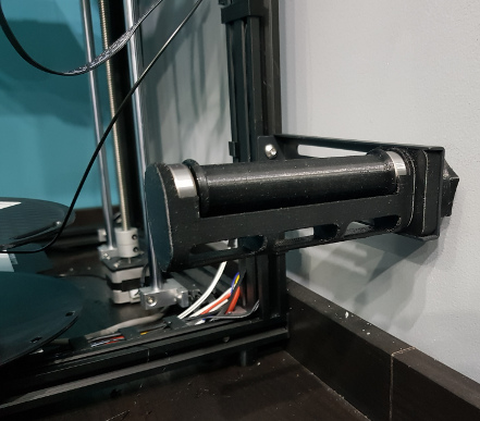
This is fitted with the supports removed. The arm it's mounted to is the Ender 5's factory arm. The square part of my model lets you mount it like this or on top of the printer once I've got a direct extruder set up.


At the risk of talking to myself, I thought I'd update. When I made this I simply modelled some holes in each end of the part and then ran a reamer through them and made some stub shafts out of aluminium to take the bearings. I wasn't careful enough making sure I reamed the holes concentric to the part so the stub shafts weren't perfectly inline with the roller. That means that as the roller rotated the distance between the top edges of the bearings got longer and shorter. There wasn't any space in the holder for that so mostly the spool just slid round the spindle rather than the spindle rotating in the bearings. I reprinted the spindle with a 12mm through-hole down the centre and then reamed it to size (holes come out undersize on my printer currently) with a cheap import reamer - not really sharp enough when compared to the smaller ones I have that are of decent quality. Made a full length shaft that was around 12mm in the middle (had taper issues with my lathe at the time) and had 8mm diameter ends for the bearings. Used my swing press (that's an overly fancy term for a hammer when you don't have the right equipment to press it in properly) to push the shaft into the spindle, set the bearings on the end and now it turns quite nicely.
When I printed the 1st replacement spindle, there were several lines in the print that didn't look right and I thought they looked like weak points....snap....I was right. I think it was caused by the fact that on this spindle the very end of the filament sticks through a hole (to retain it) into the centre of the spindle. Better ones have this go into a space that isn't right in the middle where the spool spins about. This got hung up on the arm because it didn't have a spindle in it and I think meant that each layer that came about when the tail of the filament got stuck on the holder, under extruded enough that there was no strength there. 2nd one was better (with the old spindle back in place) but didn't look perfect. Wasn't sure it was going to survive the reaming to be honest - sharper reamer would have been a lot better.
 
There's a few models on Thingiverse (search "rewind spool") that will do auto-rewind with basically a clock spring and a clutch. Not sure how reliable they are though from the comments.
There's also some very similar to my one that I took inspiration from and that lets you print the 8mm pin in one end of the spindle as part of the spindle and the other end as an insertable part - so you can stand the spindle upright on a flat end to print. My printer isn't (currently) accurate enough to get away with that. It's also worth mentioning that cheap skateboard bearings don't free-spin very much. There's a bit of drag either from grease or perhaps just because they're cheap, not sure which.
 
If you're running an 8kg spool (!) I can see why the motor setup (like power-assisted steering) might be useful but for "normal" sized spools I'd have thought you'd do as well with just the pair of rollers on bearings. The buzzer for if it's not unspooling smoothly might be useful but you can guarantee you're not in earshot if it goes off!
I went with a single central spool as ultimately I think I want the spool up top for space-saving. That has to wait until I change extruders for the direct drive version......and that has to wait until I change motherboard....and that has to wait for me to get my finger out and learn Marlin config. Nothing stopping me but time and laziness if I'm brutally honest.....that and getting side-tracked by stuff like the spindle bearings :D
 
I've only got experience of an Ender 5 Pro but the thing I can suggest is to decide which end of the scale you want to start. Either is valid, just try to avoid doing both. What do I mean? Well, you can either by something cheap with the intention of spending time and money upgrading and improving it OR you can spend the money upfront on something that's good enough to start with.
That was my theory with the Ender 5 Pro (Vs the standard 5) but I've ended up doing a number of upgrades anyway so I'm simply replacing parts I paid more for now.
Your other option, of course, is a complete self-build but that may be too steep a learning curve. I think it would have been for me.
 
At the risk of talking to myself, I thought I'd update. When I made this I simply modelled some holes in each end of the part and then ran a reamer through them and made some stub shafts out of aluminium to take the bearings. I wasn't careful enough making sure I reamed the holes concentric to the part so the stub shafts weren't perfectly inline with the roller. That means that as the roller rotated the distance between the top edges of the bearings got longer and shorter. There wasn't any space in the holder for that so mostly the spool just slid round the spindle rather than the spindle rotating in the bearings. I reprinted the spindle with a 12mm through-hole down the centre and then reamed it to size (holes come out undersize on my printer currently) with a cheap import reamer - not really sharp enough when compared to the smaller ones I have that are of decent quality. Made a full length shaft that was around 12mm in the middle (had taper issues with my lathe at the time) and had 8mm diameter ends for the bearings. Used my swing press (that's an overly fancy term for a hammer when you don't have the right equipment to press it in properly) to push the shaft into the spindle, set the bearings on the end and now it turns quite nicely.
When I printed the 1st replacement spindle, there were several lines in the print that didn't look right and I thought they looked like weak points....snap....I was right. I think it was caused by the fact that on this spindle the very end of the filament sticks through a hole (to retain it) into the centre of the spindle. Better ones have this go into a space that isn't right in the middle where the spool spins about. This got hung up on the arm because it didn't have a spindle in it and I think meant that each layer that came about when the tail of the filament got stuck on the holder, under extruded enough that there was no strength there. 2nd one was better (with the old spindle back in place) but didn't look perfect. Wasn't sure it was going to survive the reaming to be honest - sharper reamer would have been a lot better.

Aaaaaand......I've trashed it. One of the bearings had a kink in it somewhere meaning that sometimes it got stuck - you could turn it but it took more force than sliding round the bar. I tried to change the bearing but that side I was slightly undersize on the aluminium shaft so I'd put a dash of threadlock in just as a weak retainer - the proper retaining compound (eg Loctite 638) is for stuff you never want to come apart again. Only issue is I have two blue threadlocks - one Loctite and one something like A43. One of them is medium strength (like you're used to where you can unscrew things but it provides a bit of resistance) and the other is high strength...which should be red. Guess which I'd managed to use! You can heat it to destroy the compound....but then the PETG is going to melt. Now, I have a mangled bearing, mangled shaft end and it's still not off. So, I've gone with the nuclear option and ordered a foot of 8mm ground steel shaft and a foot of 25mm black Delrin. Going with the far less finicky drill a hole through the middle and push a shaft that's already the right size down the hole. Fed up with everything needing massive amounts of overthinking and fiddlyness!
 
Very nice. Articulated Pi cam no less!
Have you never had trouble with bits of filament - like the angel hair stuff you get sometimes when it oozes in travel or priming - sucked into those fans? I've had it happen a couple of times to my hotend fan and it's a right pain as you have to shut everything down to stop the fan and pull it out with tweezers.
 
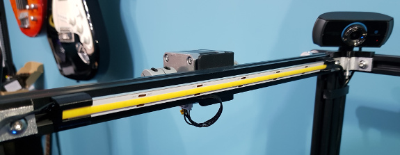
That cheap LED strip I made mounts for a while back slowly died on me. Some dropped out, some faded, some flickered and it all lost brightness. It was cheap tape and had failed in everything else I'd used it in too.....but it at least made proof of concept. Bought a couple of metres of 578 led/metre 24V COB tape, stuck it to an aluminium strip (11.5mm wide, from Wickes) for a bit of support and cooling and then made some new clips. Good job I printed three of them before I stuck the strip on and made none of them fit *facepalm*. New ones printed to include an endstop at one end and strain relief for the wire at the other. Resoldered the power output jack I'd previously added from 12V (buck convertor) to 24V (PSU), flicked the switch and it's beautiful. Was thinking I may have to make one for the side as well since I could only get 6 segments in the front but it's almost too bright already!
 
Nice. I was questioning the choice of colour....but just primer :D
Actually I was looking at the pics of yours regarding layout of electronics, PSUs etc. I took mine apart to swap the voltage for the LEDs and had a quick offer-up of the new board. Yeah, it's not gonna fit. Well, to be accurate, it will as long as I don't want to plug in some of the connections to it. So it might be a complete rethink :-/
 
My immediate thought was for a larger metal box. Mount it centrally in case I ever want a second Z stepper (and rails). Make it accessible from the top - who's damn stupid idea was it that it was only accessible if you unplug everything, unscrew it and turn it upside down?! And look at making things pluggable. Also, once slightly bigger I can spin the PSU 90° and have way more useable space. I'm thinking it's a plan things and investigate laser/vnc cutting job though. I'm bound to screw something up if I try to do it all by hand!
 
That cheap LED strip I made mounts for a while back slowly died on me. Some dropped out, some faded, some flickered and it all lost brightness. It was cheap tape and had failed in everything else I'd used it in too.....but it at least made proof of concept. Bought a couple of metres of 578 led/metre 24V COB tape, stuck it to an aluminium strip (11.5mm wide, from Wickes) for a bit of support and cooling and then made some new clips. Good job I printed three of them before I stuck the strip on and made none of them fit *facepalm*. New ones printed to include an endstop at one end and strain relief for the wire at the other. Resoldered the power output jack I'd previously added from 12V (buck convertor) to 24V (PSU), flicked the switch and it's beautiful. Was thinking I may have to make one for the side as well since I could only get 6 segments in the front but it's almost too bright already!

Finally got the time to get a picture up. Tried taking one of the setup with it off and on but either the camera compensates or you just end up with one looking either dark or overexposed. It's plenty bright enough for The Spaghetti Detective to spot problems with the room lights out....which was the main idea. Incidentally, I left it running for a while and found it was hot. Checked it and it was 41°C. Glad I backed it with an aluminium strip and didn't encase it in PLA/PETG but apparently that sort of temp is absolutely fine.

Holder on the right of the pic includes strain relief for the heatshrink'd wires. The one on the left is an endstop and they both clip into the channel on the frame. Wires coming out the left hand side are just the stepper wiring and this extrusion is the front of the machine so the light isn't in your face. Moved my stepper to the front so I could push the whole machine back far enough that all the feet would be on the table surface :D

 
I've got a plain borosilicate glass bed and I seem to have got away with it by bringing the bed temp up to 85 (which is actually closer to 80 according to an IR temp gun) and making the first layer really slow at around 10mm/s or slightly less(I forget exactly). Sticks well now but can lift slightly at a corner sometimes. An adhesion disc would probably sort that for parts that matter - the print succeeds, it's just slightly warped for the bottom couple of layers.
Hairspray also helps but is a pain to clean off if you can get away without it.
 
Ah, I see. I'd incorrectly presumed a direct link between filament size and nozzle size. So if you stuck a SuperVolcano (or something similar) in as your hotend to provide faster melting you could then get faster print time by using a wider nozzle but at the expense of fine detail.
 
Back
Top Bottom