Random 3D printing chatter

Morning Deuse. There's a piece of software called OctoPrint and OctoPi is the build that's specifically for a Pi. My initial use was to run a webcam because I wanted the remote monitoring - my 3D printer is in my office which is an outbuilding. I'm also running The Spaghetti Detective as a plugin to OctoPi and that watches the video feed and will pause the print and alert me if it thinks it sees spaghetti. It's not perfect (sometimes a bit over twitchy) but it's caught all the prints that would have turned into birds nests.
I've also shoehorned the Pi and a couple of buck convertors (one 12V for fans, one 5V for Pi) into the existing case so now I haven't got access to the micro SD card slot on the motherboard. All prints are sent to the printer over the network via OctoPi's web interface. The Pi is connected inside the case with a short USB cable to the motherboard. Pretty much everything you can do on the printer's control panel, you can do on OctoPi from a PC or an Android app on your phone.
I think it's possible to slice in OctoPrint but I can't say I've tried it to be honest. I would suspect - perhaps unfairly - that it isn't going to be as full-featured as the PC-based slicers and I tend to slice directly out of Fusion 360 where I've modelled most of the things I'm printing.
 
Right now, it looks glossy and a thing of beauty. Haven't cleaned it up or tested the threads yet. It's a Schroedinger's cat: right now, it COULD be perfect. I'll open the box tomorrow :D

The cat's alive and t'is a thing of beauty! :D

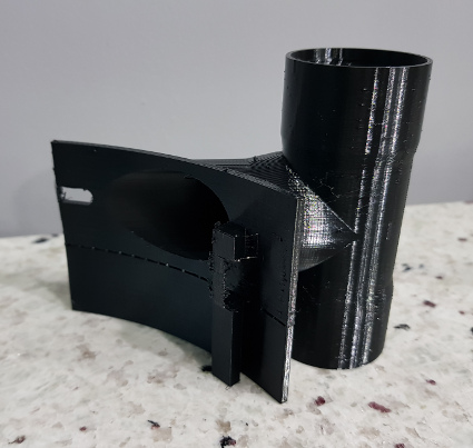
As printed. There's a flat on the bottom modelled into it. I also modelled a very thin wall at the end of the slot which I then cut out - just gave it something to bridge to. There was also a thin tower modelled under the retaining tab on the right that was then cut away.


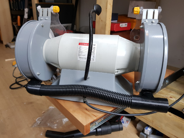
Assembled ready to go on the bench grinder. The hose thread was modelled into the print and screws on very nicely. I'd done test prints of just that bit in white PLA and they fitted but very tight. I was concerned that having increased the extrusion, it may not fit but it's great; not as tight as it was in the test parts but enough that it should be air tight and not trash the hose screwing it in.


Now all I need to do is be able to print its partner that will have a T shape through-connection instead of a right angle. To make sense of that, this is what it will fit on:


I've not really had an issue with power transfer between the two....that I'm aware of, at least. They both run off the same PSU with one power switch so I wouldn't really notice. I wonder if that has anything to do with the networking problem though. Hmmm, might be worth looking into next time I have the case open (sounds lazy but it's a bit of a mission). For reference, this gives the details of the issue: https://www.raspberrypi.org/forums/viewtopic.php?t=269898
 
@Vince Let us know how you get on with the addressable RGBs. I've got lighting run with a strip of waterproof LEDs off a 12V feed and a manual toggle switch. Worked well enough but the LEDs are all failing because it was crap strip. I knew this when I used them but I had a spare length so it was free. Was contemplating trying a section of COB LED strip but it's pricey for what it is. RGB LEDs seem an odd choice (by BTT/the industry) as they're traditionally not as good at white lighting which would seem to be their main aim - excluding decorative frivolity.

@Scougar I was having adhesion issues with PETG and hairspray wasn't helping much. I brought the bed up to 85 - although people are going up as far as 100 - and that helped. People have also said 250 for the first layer and then drop to 240. I haven't got that option in my slicer (Fusion 360) and 235 seemed best on the temp tower I printed. The main thing I changed was to reduce the speed for the first layer to 10mm/s and then nothing faster than about 40mm/s for the rest. It's slower but to be honest I'd prefer slow and hassle-free to faster and fighting it every step of the way! I also cleaned off the hairspray with IPA (not the best for the hairspray but what I had) and levelled as normal to some drag on 80gsm A4.
 
@gitbags Nice. Was wondering quite what it was until the last shot where you put the two together. Damn, now we know who's got the nuclear football.....but not how stable

@Scougar I'm not going to say you shouldn't be using glue/hairspray/tape/whatever. If I can get away without the additional faffing about though, it'll make me happier. I forgot to mention that I was also printing with no layer fan at all. I did get some warping or loss of adhesion in the last print but it's only really in the areas that are a 3mm thick vertical wall and 70mm high so maybe asking for it. Might be a classic use-case for a brim....but I don't like making life easy for myself! :D

Print came out looking mostly nice. One layer went a bit odd and a couple of layers above it so I'm thinking filament issue? Main issue is that I went too robust on the manually created support structure. No, it didn't fall over.....but I don't think it's coming off either! Threads seem to work but look very different - printed with no support, you get the classic drooping of bridging but on the one pointing upwards, that's on the side obscured by the threads. On the one pointing downwards though you can see them. I thought it was trashed but seems to work just about - should be fine after a bit of clean-up work. Now to see if I can cut off the supports and leave something I don't hate the sight of!
 
@SKILL Forgive me if I'm teaching you to suck eggs but are you waiting for the bed to cool before trying to remove the print? Not so important with a removable magnetic bed as you can flex it but more so with a rigid bed like glass.
Would be interesting to know what sort of settings you're using for bed temp, hotend temp, first layer speed and fan. Purely because I started from having terrible adhesion of PETG to glass and have got it better. So it would be interesting to know what makes it stick too well and maybe meet in the middle!

@Vince Nice. Are they any good for lighting it in a dark room? I'm thinking of the webcam getting a good picture for auto monitoring for spaghetti when the room lights are off.
 
@SKILL Wasn't criticising your handling/method/whatever....just in case it came across that way. Just meant that once you'd swapped over to the plain glass side and still found it was sticking too well that was different from my experience. Temps seem about the same though.
 
Ahh, I see. That makes sense then if we're getting the same result with more or less the same settings.

@Vince Cool, cheers. Might check those out as another option...given I will have the header for them shortly. Sleeving looks good but I detect a significant amount of "What do you even need that thing for?!” "Well, I've printed all these mounts and clips and tidies and brackets..." "Yes but those are for the printer. If you didn't have the printer, you wouldn't have needed those!” "Ah."
I get that with my mill as well as the printer. Once in a blue moon I make something that ISN'T self-servicing! :o ;)
 
If you run OctoPi you can upload the gcode to it over the network and then you have a library of files you can print at will. Now, I'll grant you it could still come out but, if you're short-sighted enough that you mount it inside a screwed-shut box with the card inaccessible, it'll never get accidentally knocked loose!! :cool:
Alternatively there are other storage solutions for a Pi mainly over USB3 (memory stick or NVME SSD in a USB adapter) but newer ones are starting to get PCIE. Probably no reason you can't run OctoPrint on a higher-grade board that will take M.2 directly if you really wanted to.
 
Nice Rilot. Great detail on it. Any good in terms of strength? (not planning to earn myself a divorce, just curious!). So for example, I managed to print the 2nd, more complicated, one of my ducts and got them fitted. Certainly this 2nd one at 50% infill (vs the 1st one's 15% - Fusion 360's infill seems more dense number for number compared to Cura) seems strong enough for decent service:


Don't print something specifically for my benefit - as I say, I'm just curious as to whether it's only for decorative items or strong enough and UV resistant (ie doesn't turn to smush if the sunlight gets at it) to make parts to be used.
As the object moves up and it fuses the bottom layer, do you need support still? Like in my pic, you can see the amount of support I had to put in as that part floated otherwise. Could you print that without the support? Or is it just that you need the support above it instead of below it. Again, just curious :D
 
Bah! The one time you actively choose to use supports and what happens? They don't stick to the bed and end up as spaghetti. So you slap a brim in to support the support and what does it do? Adds a nice brim in round the model and all the way round the support....but without touching the support. Geeeenius!
I'll model a thin pad under the support like a mini raft! Oooh, you don't want that on the build plate anywhere near the model, right? I'll move it closer....nope, entire model and raft moves. Honestly, sometimes it's like 3D printing is trying to be hard! </rant> :D
 
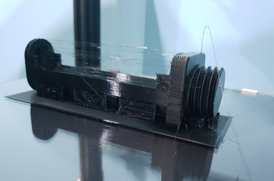
Well, the mini raft under one part worked nicely, the support stuck to that and it all worked. Made a few tweaks to it - like one wall was a bit thin and the printed thread was too big to fit (mmm, custom thread specs in Fusion to get looser tolerance, what fun!) and I didn't like how square I'd made the bottom, from a purely aesthetic point of view....despite it being there to avoid supports and make it stick well. What this print (that I'm having adhesion issues with) needs is LESS material touching the bed! Yeah, that'll help! Rounded off the bottom, made some speed holes (for lightness and maybe a bit of strength but mainly to look cool) and now it only touches the bed for just a strand or two. What could possibly go wrong?! Well, I'll need that mini raft all the way across the part.....hang on, that's just a raft and there's a tick box for that! Oh wait, you can only have a raft if you want a complicated mat of zig-zag layers, infill and surface layers. Really?! ...but I just want a single 'surface' layer, that'll do. Just set the number of those layers to zero and one surface layer....nope, denied! And you guys ask me why I use Fusion as my slicer when it's such a joy to work with! So, manual maxi-raft and away we go! You can't see the speed holes as they're full of support in this pic.


Couple of skate bearings, a printed spindle and some aluminium pins and we have a spool holder :D I'll get a pic once there's not an active spool spinning on it!

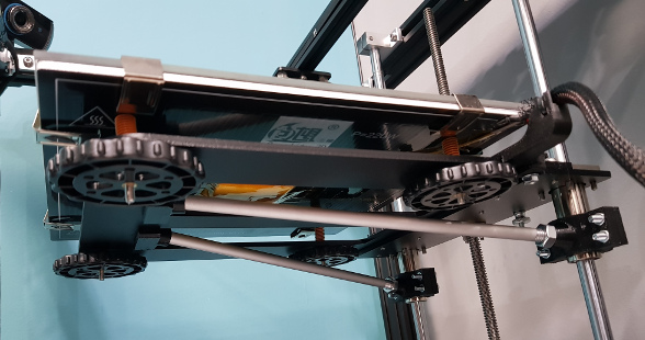
Bed braces are also in and certainly seem to make it a bit stiffer. It's by no means rigid but short of another two slides, leadscrew and stepper, this is as good as it gets. You can wipe the bed without one end backing away from you now.
 
Well, I'm trying not to but it looked pretty awful with a squared off bottom. The thread is essentially an M30x3.5mm (ISO Metric Course M30) but I edited the thread configuration data to add a "6g Loose" tolerance for the M30 thread. It's still ISO standard but at the minimum (modelled rather than printed!) dimensions to be in spec.
Thread data is stored here (substitute the <Install ID> with whatever your install folder is - not sure if they're unique or per-version:
%localappdata%\Autodesk\webdeploy\production\<install ID>\Fusion\Server\Fusion\Configuration\ThreadData\
Added this in at the end of the M30x3.5 section:
Code:
      <Thread>
        <Gender>external</Gender>
        <Class>6gLoose</Class>
        <MajorDia>29.522</MajorDia>
        <PitchDia>27.462</PitchDia>
        <MinorDia>25.306</MinorDia>
      </Thread>


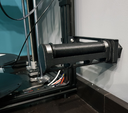
This is fitted with the supports removed. The arm it's mounted to is the Ender 5's factory arm. The square part of my model lets you mount it like this or on top of the printer once I've got a direct extruder set up.

 
Now you've finished obsessively procrastinating tidying everything (well done, by the way) you might actually have to do some painting! ;):p:D

Shaker looks like a PC fan. One or two blades removed to unbalance it or a counterweight?
 
I dunno, they go to all that trouble to make the fan spin smoothly and what do you go an do?! ;)

BLTouch just arrived. Need to find enough sanity to wrap my head around it all now. Too many plates spinning at once at the moment!
 
That's alright; moments of idiocy seem to be par for the course most of the time, let alone currently! I printed the spindle for my spool holder without pins as I needed a flat base to print it. Then I carefully machined two short pins (didn't have 8mm dowels) to go in the end and into the bearings. Dawned on me afterwards I should have just made one pin that went all the way through - much easier, faster and would have been straighter!
My existing gooseneck light on that grinder is both pathetic and seems to have mains voltage where it shouldn't - give you one guess! So today's idiocy involves trying to dismantle an LED GU10 bulb to see if it can be split (LED at the top of a gooseneck and transformer at the bottom) because I'm too cheap to spend £30 on one made for me (with reviews of it failing quickly). The good news is that at a bare minimum, what I've managed to achieve is one less bulb on the ceiling! :D

Didn't have ABL before so looking forward to it. Have to wrap head round Marlin (excuse!) and generally get finger out (real reason!) before I can use it. Probably need a day where my head doesn't feel like it's trying to turn itself inside out though!
Have managed to get the bed supports done though:

 
Nice. There seem to be plates either side of your gantry. Dual extruders planned?

I made printed mounts that tip my LEDs downward rather than at your face. They just clip into the slot. I'd share the model but your strips are bound to be a different size/shape.

This evening I stabbed holes in the ceiling...for the rain to drain out more easily and hopefully hit the buckets instead of the vents at the back of the monitors.:rolleyes:
 
That's the spirit. And if the parts don't fit together on first print, just "press fit" them in your vise :D
What me? Yeah, ok I tend to ream holes to size presuming they won't print to size rather than be bothered to get things properly sorted. Works nicely though! When I get the SKR in I'll try harder....maybe ;)
 
Anyone got any experience with suitable multipin connectors for a 3D printer?
I'm going to order the JST XH pins and shells to wire up the new motherboard with wire long enough to properly reach. What I was thinking of doing was having a plugged connection between the control box and the chassis wiring so it's possible to take the box out without having to strip the wiring off the frame. There's a 37 pin D-dub (like a glorified printer port or VGA connection) that would take the signals but I doubt it would be suitable for the bed and hot end! Before I disappear down the rabbit hole trying to find things that night work, am I reinventing the wheel here, is this something that there's already a recognised solution for?
 
Back
Top Bottom