• Competitor rules

    Please remember that any mention of competitors, hinting at competitors or offering to provide details of competitors will result in an account suspension. The full rules can be found under the 'Terms and Rules' link in the bottom right corner of your screen. Just don't mention competitors in any way, shape or form and you'll be OK.

ripped capacitors off GPU

Associate
Joined
26 Jul 2011
Posts
191
Location
West Yorkshire
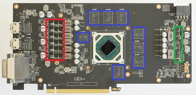
Picture taken from another thread of mine, Vince kindly showed me where to put the heat sinks for a future universal gpu core water block.

However I thought I'd clean up the air cooler for the fun of it but ripped off 4 of the 5 capacitors to the left of the red rectangle while pulling off the stock heatsink that is on the chips in said rectangle.

I glued them back on but my GPU got up to 80*C as soon as the game loaded into the menu so I shut it down (it was just going to keep going up).

So I took it apart again, cleaned the metal contacts on the capacitors and on the board, reglued with super glue (instead of wood glue as it was all I had the first time) and it's better, but running around 70*C instead of the original 60/65 before I broke it.

Is a higher temperature a symptom of 1 or more capacitors not making contact properly?

f35OuV0.jpg
 
Associate
OP
Joined
26 Jul 2011
Posts
191
Location
West Yorkshire
I'm speachless. You need to order some replacement capacitors of the same value (measured in Farads) and solder them on properly. I'm guessing you've never soldered before so do you have a friend who can help you?

I haven't soldered since school almost two decaded ago. I have no friends.

I've been gaming on it though for a good half hour, I reduced the power limit back down to stock (non-overclocked) to manage the temperature issue, so super glue wasn't the worst thing...

In fact I don't get why it's so shocking, so long as the two contacts that come out of the capacitor are in contact with the boards contacts then surely that's the goal isn't it?

I'll try upload the pics I took. (EDIT - I have no pics)
 
Associate
OP
Joined
26 Jul 2011
Posts
191
Location
West Yorkshire
Yes I reapplied some compound on the GPU core before putting the heatsink on then all the screws back in, then the shroud with fans on top of that.

I'd blame the very old compound (ATRIX - made in China) but it's still working for my CPU.

I've searched all the numbers on top of the capacitors (5KW38 270 16v) but there's still so many to choose from maybe I'll just hope it keeps on working and if not buy a new card.
 
Associate
OP
Joined
26 Jul 2011
Posts
191
Location
West Yorkshire
Wow, this is a popular topic. First of all, it's not a joke, I don't have a soldering iron so I glued them on.

Second, it didn't heppen while I took the heatsink off, after I took that off I took off the small length heatsink next to the capacitors but as it's on with a sticky thermal pad it was very tough to get off, I knocked the capacitors and 4 of them came off with it.

I didn't use a new thermal pad as I don't have any. I may of ripped the solder pads off yes, can they be repaired/replaced with a dollop of solder?. I have no idea what temperature the capacitors run at.

They are surface mount (there is not a hole through the board).
 
Associate
OP
Joined
26 Jul 2011
Posts
191
Location
West Yorkshire
lol, I repeat, this is not a joke, but glad I entertained everyone.

I didn't take pics of it because I hastily went into DIY repair mode to pretend I never did it. But even the after photos you wouldn't be able to tell.

It appears some may think I used super glue in place of solder, I didn't because of course it's not conductive; So I place a spot inbetween the pads so the conductors pins had the best chance of touching what metal was left of the pads.

Also the glue I used didn't mention anything about heat whereas the first one I looked at in the shop said it wouldn't work, so I thought it was all over until I found the Bostik's tube.

Well, thanks very much for all the genuine help and I'll either try to find someone to sort it for me or I'll treat it as a lesson learned, get a new card and use this one for further experiments.
 
Associate
OP
Joined
26 Jul 2011
Posts
191
Location
West Yorkshire
So I lapped the heatsink to try reduce the temps but it's not helped so it must be the broken capacitors causing increased temps.

Question : do I need solder pads or can I just makeshift the connections with some solder? (surely it's the same difference)
 
Associate
OP
Joined
26 Jul 2011
Posts
191
Location
West Yorkshire
No pics Vince sorry.

Solder pads are kinda needed. The pcb connections are with small tracks running along the fibreglass – to electrically connect a component to these tracks you need a pad for the part’s legs to be soldered to. If the pad has been lifted/removed then you will need to solder to the track that went to that pad – probably meaning scraping away some solder-resit/conformal-coating that’s on top of the track.

So, erm, find the track that originally went to the pad, use a scalpel and v v carefully scrap away the coating without damaging the track, so you can solder to it. tin and solder as normal, and check with a multimeter against the other end of the track, at either a solder-pad or test point.

If that pad just goes to a via (small hole running through the fibreglass to connect one side of it to the other), then you’ve got more fun/problems…

Solder alone wont stick to the pcb board, so without a solder pad or track, you've got a challenge... If you try "makeshift" and somehow create a massive solder-blob to bridge a gap where there used to be a pad, then it won't have the strength of the original pad and it probably will require so much heat from the soldering iron that you could goose something...
(has visions of solder being melted everywhere, accidentally bridging existing pads, damaging components, etc...).

finally - what anti-static protection are you using when handling this pcb?

You have just described what I read on this site earlier : http://www.circuitrework.com/guides/4-7-1.html , I think I can do that. I'll order some stuff when I can and make sure I take pics of the repair.

And I've not got any anti-static protection, I don't understand it. The boards been resting on my mousemat all day today while I lapped the heatsink.
 
Associate
OP
Joined
26 Jul 2011
Posts
191
Location
West Yorkshire
Needed to take heatsink off again to measure capcaitors, one of which was about to drop off so I took the opportunity to get a picture, this is the best I could get with a smart phone.

Can you tell what condition the solder pads are in? Are they OK to be soldered to as is?

oops sorry for huge photo.

j9P0RKA.jpg
 
Associate
OP
Joined
26 Jul 2011
Posts
191
Location
West Yorkshire
'cause I like to do things myself.

Do you reckon I'll need new capacitors? Are they likely damaged inside from been knocked off the board?

I think I'm going to order a soldering iron kit, won't bother with that expensive cold solder or doing solder pads.

I'll just hope that resoldering capacitors (new or old) will fix it and lower my temps back down.
 
Associate
OP
Joined
26 Jul 2011
Posts
191
Location
West Yorkshire
I ordered a £15 soldering kit off Amazon but it's been a few weeks since I was looking at them so forgot to get the kit with a multimeter. Went ahead with soldering the original capacitors I tore off.

First I scraped the solder pads to remove any glue etc.
oslDngO.jpg
you may struggle to see solder joints as phone camera is rubbish but you can tell the capacitors are wonky so you know I did it
40mlJq8.jpg

a7mSRZD.jpg
right hand side ones in the below photo
ycSv0zV.jpg
unfortunately this hasn't helped temperatures at all so I've ordered some more capacitors, rated same voltage and ohms but a tiny bit smaller so might be easier to work with as my skills are very limited, it took me about 2 hours to solder those 4 on. The first half of that time I achieved nothing, it was very awkward.
 
Associate
OP
Joined
26 Jul 2011
Posts
191
Location
West Yorkshire
Great explanation thank you, that'll help a lot. The legs extended only half a millemeter beyond the plastic base under the capacitor, I don't know know if that means they snapped off a little when I knocked them off or not but it was difficult.
 
Associate
OP
Joined
26 Jul 2011
Posts
191
Location
West Yorkshire
Well I managed to solder the new capacitors on, forgot to take a picture though! as I had just spent a while putting my new motherboard, CPU and RAM in case then thought while I'm at it I should fix the GPU before it all goes back together. So that's what I did; Then to realise I had ran out of thermal compound! haha. £16 next day (Saturday) delivery for a £6.50 syringe of compound, it was worth it though.

I'm certain the new capacitors have worked, to a degree. I can't bump up the power limit in the GPU settings anymore (it was on +50%) but I think I'm getting far superior performance anyway thanks to the new DDR4-Ryzen 5 3600 set up.

While it was broke : as soon as I opened a game the temps shot up past 80*C (I couldn't even get past the games menu) but now they're around 70*C for several gaming sessions.

Am I right in thinking that a multimeter placed either side of the capacitors I've soldered - while still on the board, will tell me if the capacitor is connected to the circuit?

I'm wondering if I'm unable to increase the power limit because one or two capacitors don't have a connection/are soldered badly.
 
Back
Top Bottom