

Caporegime
- Joined
- 1 Dec 2010
- Posts
- 53,766
- Location
- Welling, London
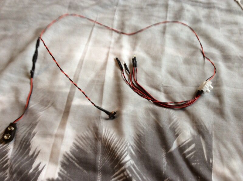
im currently building my Millenium Falcon cockpit. I'm adding an LED driven fibre optic lighting system to it.
The top photo shows the LED circuit with a 9V battery attachment, and the bottom is a 4XAA power pack. What connection do I need to integrate the two so the LED's run off the power pack?
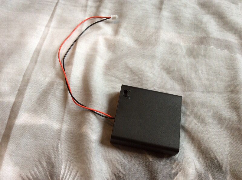
The top photo shows the LED circuit with a 9V battery attachment, and the bottom is a 4XAA power pack. What connection do I need to integrate the two so the LED's run off the power pack?

")