*** The DIY Audio Thread ***

Soldato
Joined
13 May 2007
Posts
7,004
Location
On the wagon, sorta
Damian666.

I'm looking for the parts to upgrade my DAC like the LAMPUCERA. I can find the Oscon caps at Farnel but not the Winma. Could you send a link please. Thanks.

Edit.
Forget that, i see you went for the Tat's. Where can i get them and how much please.

My tantalums are from the speedy shop, and are only about £2 for the 10 i orderd. postage is £4. odd so you need to get an order together to make it worth while ordering.
 
Soldato
Joined
13 May 2007
Posts
7,004
Location
On the wagon, sorta
Been shopping today :D

got me some nice 1% tolerance resistors for my bridged amp project, also got the caps though still have a few bits to grab for it and 2 more LM3886 IC's on order.
parts.jpg

Also started on my pre today though this is as much as im doing, still have to order some parts from it but its looking good!!!
pre.jpg
 
Soldato
Joined
2 Sep 2006
Posts
13,483
Location
Portland, OR
I have a question on the CMOY.

I am getting sound but it's mono...left/right is not working and I think it's because I'm confused on the grounding.

Do I connect the output ground to the input ground on the headphone sockets, or do I connect it to the virtual ground?
 
Soldato
Joined
1 Oct 2004
Posts
10,772
Location
Cambs/Herts
I have a question on the CMOY.

I am getting sound but it's mono...left/right is not working and I think it's because I'm confused on the grounding.

Do I connect the output ground to the input ground on the headphone sockets, or do I connect it to the virtual ground?

Can you provide a circuit diagram? Unless you're trying a star grounding system, one ground should be sufficient for test purposes. This is the "middle rail" of the rail splitter, if you're using the simple power supply circuit.
 
Soldato
Joined
2 Sep 2006
Posts
13,483
Location
Portland, OR
I am using this diagram...this is of 1 channel so obviously it's repeated on the other side of the amp for the other channel.

42417218au6.png


So do I need to connect the two signal outs to the virtual ground as shown in blue? Do I need to connect the signal input ground to the same virtual ground?

I'm confused :/

img3559xb3.jpg
 
Associate
Joined
9 Mar 2008
Posts
1,039
You need to connect the ground terminal of the input jack(s) (for a 3.5 mm input jack, there is a ground pin, and for RCA jacks there is a ground 'ring') and the ground terminal of the output jack(s) to the virtual ground - at least, thats what i did!
 
Soldato
Joined
2 Sep 2006
Posts
13,483
Location
Portland, OR
ok thanks.

I think my problem was just down to messy soldering and I don't really like this strip board much so I rebuilt the whole circuit on pin board. I like it much better...I think I'll be buying this stuff instead. its getting late now but I will test it out tomorrow. it looks a heck of a lot better than before (ignore the lm386 opamp in there :) ). I also realize those grounding wires will go to the 3.5mm socket rather than right on the input cap there.
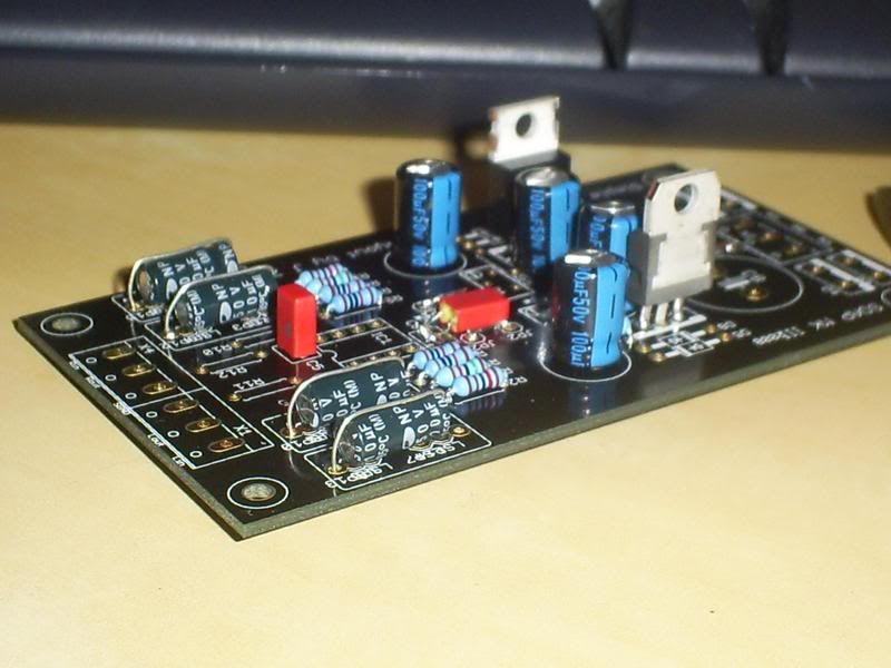

img3571aq6.jpg

img3569mq3.jpg
 
Soldato
Joined
1 Oct 2004
Posts
10,772
Location
Cambs/Herts
Personally I think you'd find stripboard a lot easier to work with. It allows you to do things like this:

dsc06081largeqi4.jpg


Which would probably have been impossible on a pinboard of similar dimensions!

That's my Cmoy amp by the way.
 
Last edited:
Soldato
Joined
2 Sep 2006
Posts
13,483
Location
Portland, OR
I am still having problems with my cmoy. The + and - rails are split correctly into +6.4V and -6.4V but as soon as I plug in the opamp it changes to 7.4V and 5.4V.

I only get sound out of 1 speaker and it's severely distorted. can anyone spot anything wrong with my setup here? I have the 3.5mm jacks both grounded to the virtual ground.

img3572lg0.jpg

img3574ue9.jpg
 
Last edited:
Soldato
Joined
15 Jun 2006
Posts
3,900
Location
Swindon
Always used stripboard myself. Built many things on it but would always reccomend you thouroughly check that adjacent tracks arn't joined, run a knife down them and then the edge of a piece of paper, usually does the trick ;) .

Heres a shot of the solderside of part of a decimator effect I never finished. It worked in prototype but was very messy, then after completing this board (one of many needed) I found it had clock noise leaking through which wasn't on the breadboard version! Never did finish it :( , but a good example of soldering on stripboard;


As you solder, have the board secure and facing you slightly at an angle. Place the iron on the far side of the component lead and feed solder into the near side, heating the lead as you do this (a slightly tinned tip will make this possible). It will then flow and make a good connection. A joint should take well under a second. DIP's are good, you can go from one to the next and have them all done in a few seconds. If your moving about the board and the iron is not soldering for any time then clean and tin the bit.

I will start a thread about my new project soon. Its a 2.1 system for my Uni room. I may put the thread over in sound city and link it here; heres a taster anyhow, just the .1 so far ;) :


And a link to the thread already ongoing at DIY Audio:

http://www.diyaudio.com/forums/showthread.php?s=&threadid=128672
 
Associate
Joined
5 Dec 2003
Posts
561
Location
Bristol
When I was waiting on my OPA2132's I tried a few different op amps and most were horrible not suitable for an audio amplifier application. They were very crackly and noisy. I would wait for your chips to come before getting too worried.
 
Soldato
Joined
2 Sep 2006
Posts
13,483
Location
Portland, OR
i just discovered that I wired up R3 and R4 in my schematic wrong and this is why the amp was not working.

It now works and sounds lovely....I do get some clipping at high volumes and I hope the LM741 will sort that out. Also would larger caps on the PSU circuit help? Currently I have 220uF 35V rated caps there but have some spare Sanyo WG 1500uF 16v caps I could try?
 
Back
Top Bottom