*** The DIY Audio Thread ***

Soldato
Joined
28 Mar 2005
Posts
13,678
Location
Drunken badger punching
My DIY RA-1 clone:

RA-1Clone01.jpg


My uber modified Ariston RD80 TT with Kuzma Stogi tone arm on DIY wall shelf:

TT01.jpg


More info here:

http://forums.overclockers.co.uk/showthread.php?t=17853900&highlight=startername_danza
 
Soldato
Joined
13 May 2007
Posts
7,004
Location
On the wagon, sorta
Well after a few weeks of poverty due to my car and other bills i managed to scrape together some pennys to grab myself the Toroid transformer ive been needing to progress my chip amp project.
managed to get myself a 230va 2x25v @4.50a, cost me £30 shipped and looks great.
Started making a rough test plate to test the amp on, just need to get some TIM tommorow and sort out some heatsinks, will try and get some pics up soon as possible!
 
Soldato
Joined
15 Jun 2006
Posts
3,900
Location
Swindon
That tapped horn looks like lots of fun! If you've got the space it seems an ideal sub solution with good extension and probably very low distortion (owing to the relatively high effeciency). Is the sound very tight? Never really heard horn bass before.

Since the thread has been revived I shall post a bit of progress. This time with the speakers. I have built up both midrange chambers. Each house 2x4" midrange drivers (Audax HM100Z0 if anyone wants to know!). The chamber should simply stop the backwave as much as possible to reduce reflections through the cone (which is very light on these drivers to give good transient response). The wavy cuts are for diffusion, idea being that the sound scatters and with this chamber filled with wadding the sound would likely need to take a long route before ever getting near the cone again. It also tapers toward the back (as per B&W tapering tubes idea). This also recuces parallel sides and hence standing waves/resonances. Furthermore, these chambers are fitted in the overall box (which also houses the planar tweeters) and between them is a fill of sand. This adds mass to reduce cabinet resonances. Picture of inside mid chamber:


With 96db sensitivity per speaker and 2x100W RMS amplifier, a pair can be expected to produce peaks of 124db at 1metre across the mid band :eek:. Pointless since the bass won't keep up (below 60hz anyhow) and it would be literally painful, but interesting nonetheless :p
 
Soldato
Joined
4 Jan 2004
Posts
20,803
Location
¯\_(ツ)_/¯
That tapped horn looks like lots of fun! If you've got the space it seems an ideal sub solution with good extension and probably very low distortion (owing to the relatively high effeciency). Is the sound very tight? Never really heard horn bass before.
It's kind of hard to describe the sound, I guess effortless is one of the words that springs to mind, and it does sound very nice with music... It's hard to know what you mean by tight, but it does not sound boomy or muddy with the levels well adjusted and the crossover set with a steep slope. I've been listening to it a lot since I've built it and found it hard to find any faults really, in fact I want to build another one! :eek:

I definitely prefer the sound of my horn subs to the (commercial) sealed and ported subs that I already own, but it feels unfair to compare them as the horn is so much bigger! :D

With that being said, it doesn't require huge amounts of floor space since the footprint is around 45cm x 35cm. The tallness makes it a little intimidating tho. ;)

I really suggest you try and hear some horns, either tapped or the more conventional back loaded ones. There are a fair few people over at DIYaudio who I'm sure would be more than happy to let you hear them, in fact Swindon isn't a million miles away from Bristol so you're more than welcome to come and hear mine if you want. My first diy speaker was a traditional back loaded horn (autotuba) sub before the tapped horn so I already knew what the horn sound was like, but I had not heard them before this. The autotuba only uses an 8" driver and I was pretty shocked how well it performed, but like anything good, you always want more, hence my tapped horn. :cool:

I like your mids by the way, they kind of remind me of the Danley Synergy horn. What tweeters do you plan to use with them or are they full range drivers? I've been looking into building some sort of mid/tweeter diy speakers but there are so many options, I'm currently looking at building a small line arrays.

Finally, I think it's better to have a speaker than can achieve high spl, as you already mentioned, even if you don't ever turn them all the way up to 11, you still get really low amount of distortion, and to me this sounds a lot nicer even at low volumes.
 
Associate
Joined
21 Oct 2002
Posts
2,022
heres my latest headphone amp.

It sounds utterly fantastic.

19062008015dx9.jpg


The small circuit int he bottom right is a dc offset sensing circuit, as soon as it detected dc (35mv) it flicks the relay and stops any damage to the phones. IT also has a delay of 35 seconds for powerup, this protects the phones from tube transients (12v!) at turn on and off).

The stacked circuit at the back is a mosfet bounce / debounce for using a bulgin illumated switch. There is avery samll transformer mounted that is always on, this controls the relay for the main, and to cut the supply to the muting circuit on turn off, otherwise the rail capacitance keeps it going and exposes the phones to a turn off thump.

The circuits on the right are JISBOS, high end discrete unity buffers. The grados love the current theses things put out!.
 
Associate
Joined
21 Oct 2002
Posts
2,022
now its all mounted i need to finish the front panel, and shorten all the wires to their minimum. The whole lot is modular and pluggable!
 
Soldato
Joined
15 Jun 2006
Posts
3,900
Location
Swindon
Really quality construction there Adam! Well planned out, bet it sounds great. The DC protection makes sense, most power amps need it so why not with many headphone amps, quality headphones can cost a lot too!

I have planar tweeters to go with the mids, Hi-Vi RT2E-A. Match up nicely, like I say the mids have light cones and large motors so as such good transient response, so the virtually weightless planar matches very well. Also has good sensitivity. Distortion does seem to be very low as it should be. These can pick out a lot of low level details very naturally and have an almost monitor like quality in that respect (which I wanted).
 
Soldato
Joined
13 May 2007
Posts
7,004
Location
On the wagon, sorta
Well got some pics of my rough test bed, phone pics though so sorry in advance.

Heres the transformer i got, theres some real weight in this so i presume its a quality one. wiring seems simple enough so shouldnt be a problem.

DSC00842.jpg


i need to sort some heatsinks and some slow blow fuses before i can power it up for the first time.


DSC00844.jpg


DSC00843.jpg


DSC00841.jpg


Ill post as soon as i get this puppy powerd, should sound pretty good, i also need some advice on heatsinks so ill post a pic of the possible one i have to find if it will cut it or not!
 
Soldato
Joined
13 May 2007
Posts
7,004
Location
On the wagon, sorta
pretty sure all the wiring is spot on. tonight i got given a cambridge audio A1 MK3, the power amp chip is blown across about 4 or 5 pins, i know this would be an easy fix but im woundering if there is a way to work around that and use it as a pre amp for my amp, so that all the circuits with the volume/tone controls can be used still and wire to mine to do the bulk of the amplification?
 
Associate
Joined
21 Oct 2002
Posts
2,022
you will need a schematic. Unless you can work it out from the boards (where the preamp ends and the power amp begins).

Can you give me the schematic for your power supply. I just want to check the ac wiring.
 
Soldato
Joined
13 May 2007
Posts
7,004
Location
On the wagon, sorta
ok in need of a little help, somehow ive managed to short my tranny, im getting novoltage across the secondrys atall when plugged into the mains now, im getting a circuit connection over each of the secondrys but not from the primary to the secondeys or beween either of the primarys. have i burnt out a piece of copper wire? is there a way to fix this and will it be to hard?
 
Soldato
Joined
13 May 2007
Posts
7,004
Location
On the wagon, sorta
ok, time to own up to being complete idiot, turns out the leads on the primaries are coated in a non conductive layer that needed stripped
ill duck as you hurl the abuse :( 
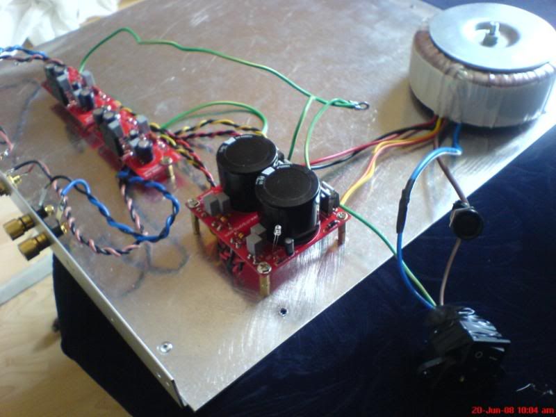
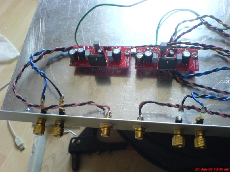
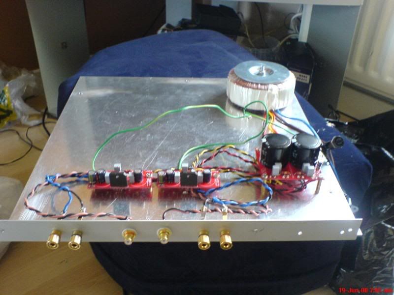
i feel like an idiot, even more so now, i mesured rails and was getting 37v dc from each of my psu rails so i rigged up my amp board, pop went a cap and i nearly **** my self and then the lm3886 chip poped aswell, luckily i have another board to get things up and running again though ill have to do it a channel at a time, a new chip and cap shouldnt break the bank, now just to figure why it went pop!
All my wiring looks fine, im getting 37 volts dc on each rail from a 230v 2x25v tranny, so the power is about right, my v+/pg+ and v-/pg- are all wired up properly, one + and onw - from each to the amp boards.


Edit, ok i think my rails are coming out reversed on one side of my psu, i went to check voltages again and noticed that on the left sideif i put the posative point of the meter on v- and the negative point of the meter of pg- the indicator trys to go into minuses but if i reverse and put red to pg- and black to v- it shows voltages in the + side of the scale instead of the minus side yet on the right hand side of the psu the rails read red to v+ black to pg+ in the positive side of the scale. does that make sense?
 
Associate
Joined
14 Apr 2008
Posts
1,230
Location
Manchester
Looking at that you seem to have two ground rails (-PGND and +PGND) without seeing the rest of your design, i'd say those should be tied together - but this depends on the rest of the design.

As regards measuring the voltage, your meters black (-ve) should always be connected to PGND, then on connecting the red to +V the meter will read a positive voltage and connecting to -V will read a negative voltage, this is correct as you have a dual rail power supply providing +,- and 0V

Unless of course you wanted two single rail supplies, in which case the design is wrong.

Do you have the schematics for the amp boards?
 
Last edited:
Associate
Joined
14 Apr 2008
Posts
1,230
Location
Manchester
Hmm as long as you've followed the instructions for the connections it seems ok, blowing a cap/chip usually suggests you have the polarity inverted but so long as you've done what it says then it should be ok.

If you've bolted the heatsink to the chassis, make sure the chassis is also grounded properly so that you don't get a voltage across the two.

Otherwise you may have a short somewhere in your soldering.
 
Back
Top Bottom