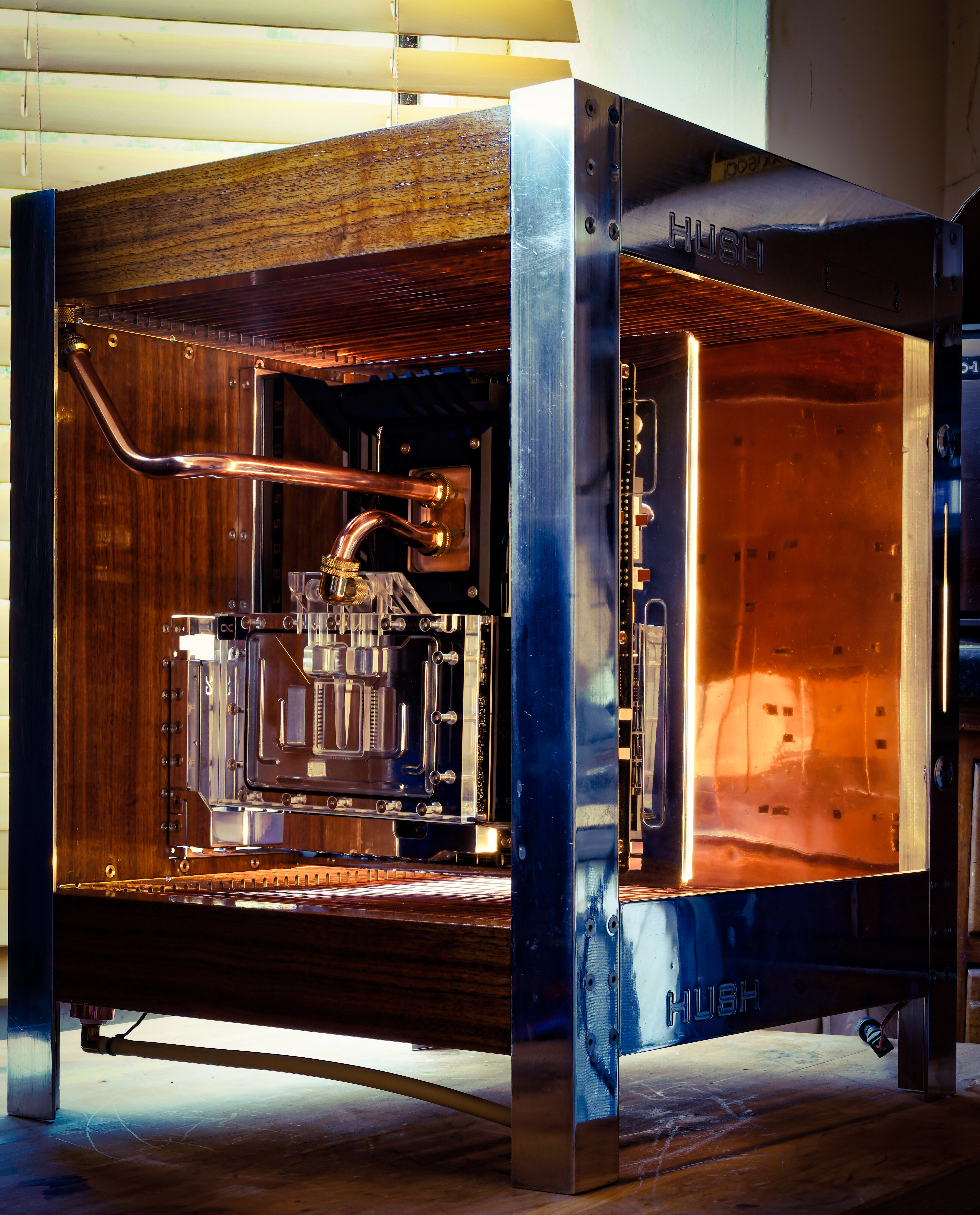
What you need is some nice easy soft tube! ....is what I kept telling myself when I was cutting the glass tubes. Hey, on the bright side, yours don't break or give off a nice abrasive dust that you want to avoid breathing in when you cut them!

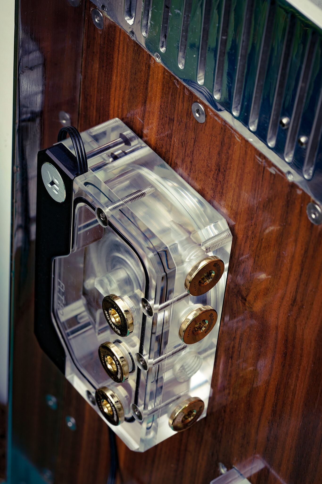
That CPU-GPU link is awkward. Too close in one dimension for either of those ports. A few suggestions
* Could you swap GPU ports and go in where you have the temp sensor? Direction of flow supposedly doesn't matter on some blocks.
* If you went for the first port you've shown, your 45's are too tall and it's never going to meet. You might strike lucky on some non-rotary 45's or even just one of them. Not as tall so might get you the line-up....but could also point in entirely the wrong direction. You've got two ports so two threads to play with so you're doubling the chance of one of them pointing in the right direction. You may also find that some fittings are 'clocked' differently - ie the thread starts in a different position so they'll end up pointing in different directions when tightened. Barrow also do a 1.5mm 'extension' or spacer. Essentially a washer with an O-ring in the back. Given the G1/4 pitch, that ought to (at least in theory) get you 44° CCW rotation of the fitting.
* Would a double or triple snake fitting work and not look too horible?
* Is there enough room to put 90° fittings on both ports and then your line-up is adjustable by adding height to one or both with small spacers/extensions.
* Are you in range of an offset fitting? Some go quite a distance now - EK do one up to 28mm offset
EK: 3, 7, 14, 21, 28mm
Alphacool: 8,16mm
Barrow: 14mm
You'll definitely get a tighter bend by bending the tube long (more leverage for a start) and then cutting the end back. Measure once, cut twice, swear many times
You could always anneal the tube with a blow torch (heat to a dull glow and then let cool naturally) as that will make it softer and 'bendable' without snapping. Copper will work-harden too so it'll get harder as you're bending. It may require re-annealing half-way if you're having that much trouble with it.
Last idea would be a block of acrylic/delrin, steel even - copper's too pricey and you don't want aluminium in your loop. Brass maybe? A square prism (square bar) with a hole most of the way down the middle, tapped G1/4 at one end for a stop-plug. Then a G1/4 hole tapped in the right place for straight m/m rotary fittings (if enough room!) to connect to your ports.


 PSX_20230429_181207
 20230429_152606~2
 PSX_20230429_174845
 PSX_20230429_175205
 PSX_20230429_180058
 PSX_20230429_175608
 :
: PSX_20230503_132224
 PSX_20230503_132414
 PSX_20230510_134520
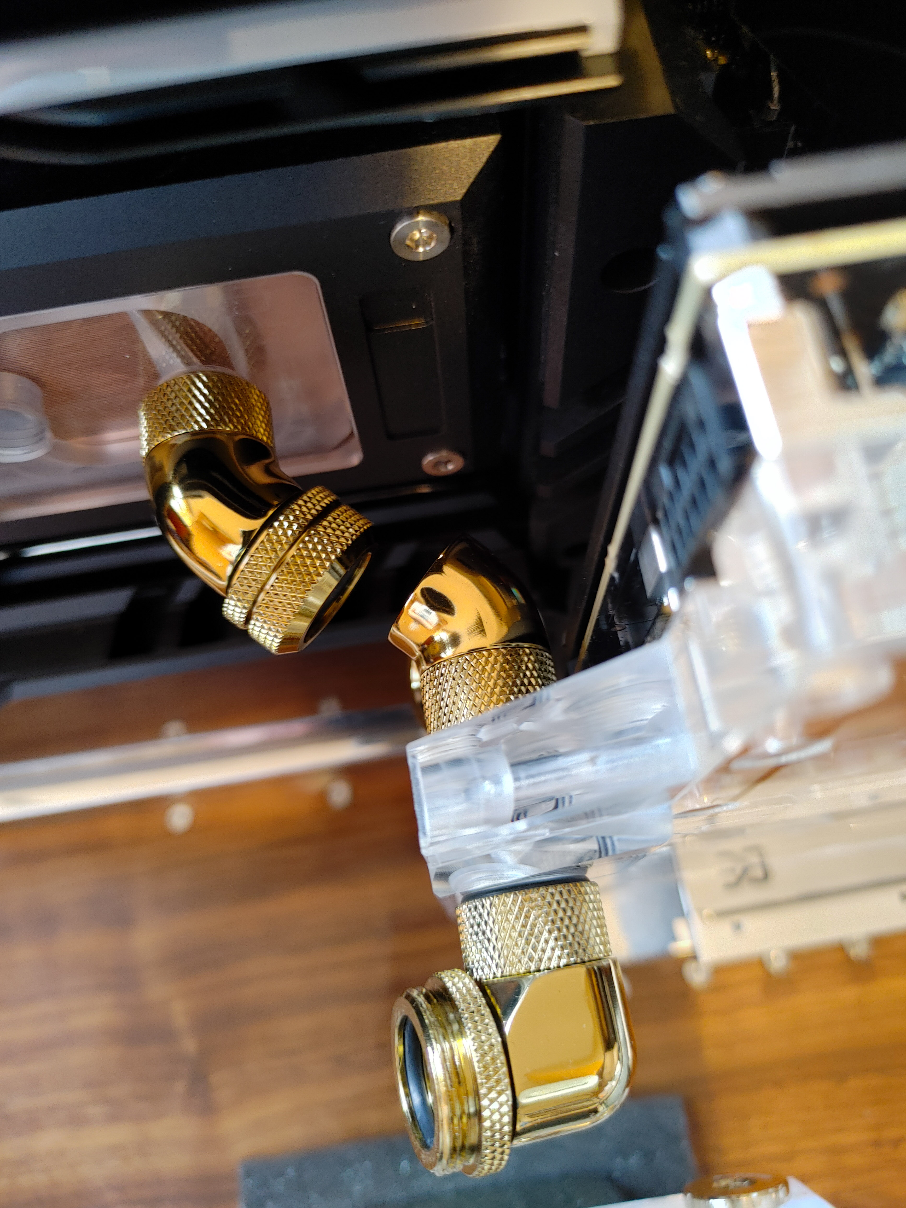 PSX_20230510_135355
 20230508_125244_HDR
 20230510_015804_HDR
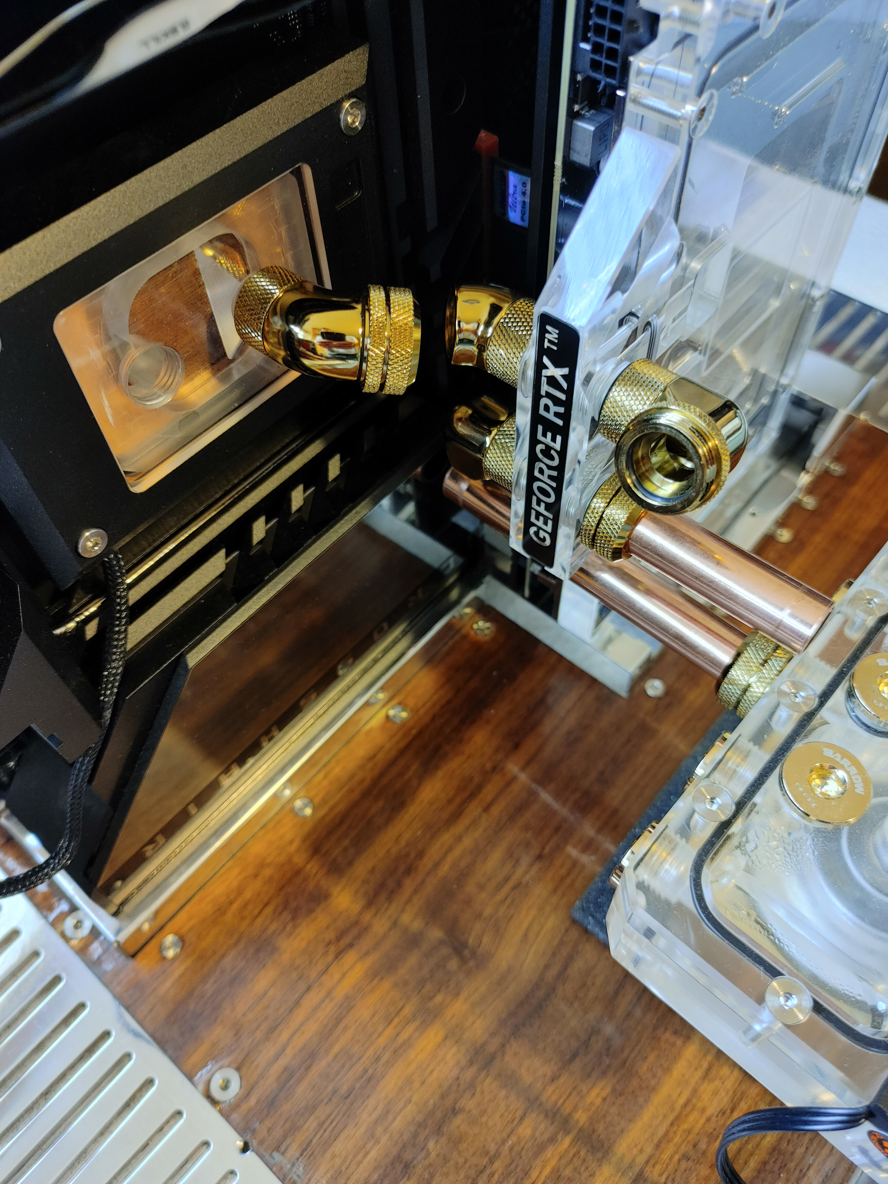 PSX_20230510_140954
 PSX_20230510_141209
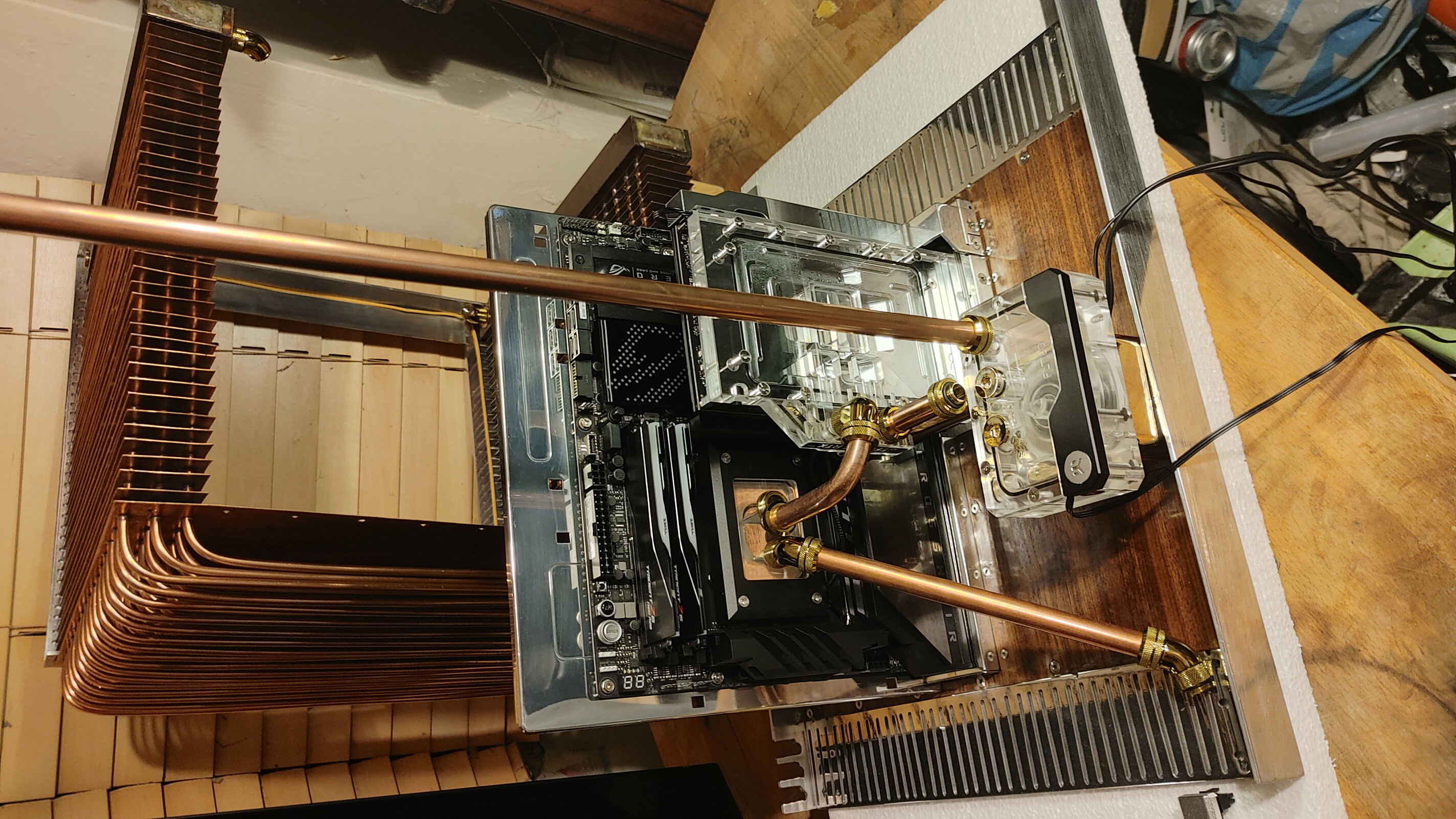 20230510_015915_HDR
 20230510_015729_HDR

 PSX_20230606_094101
 PSX_20230529_032227
 PSX_20230528_013800
 20230611_142816_HDR
 20230611_143008_HDR
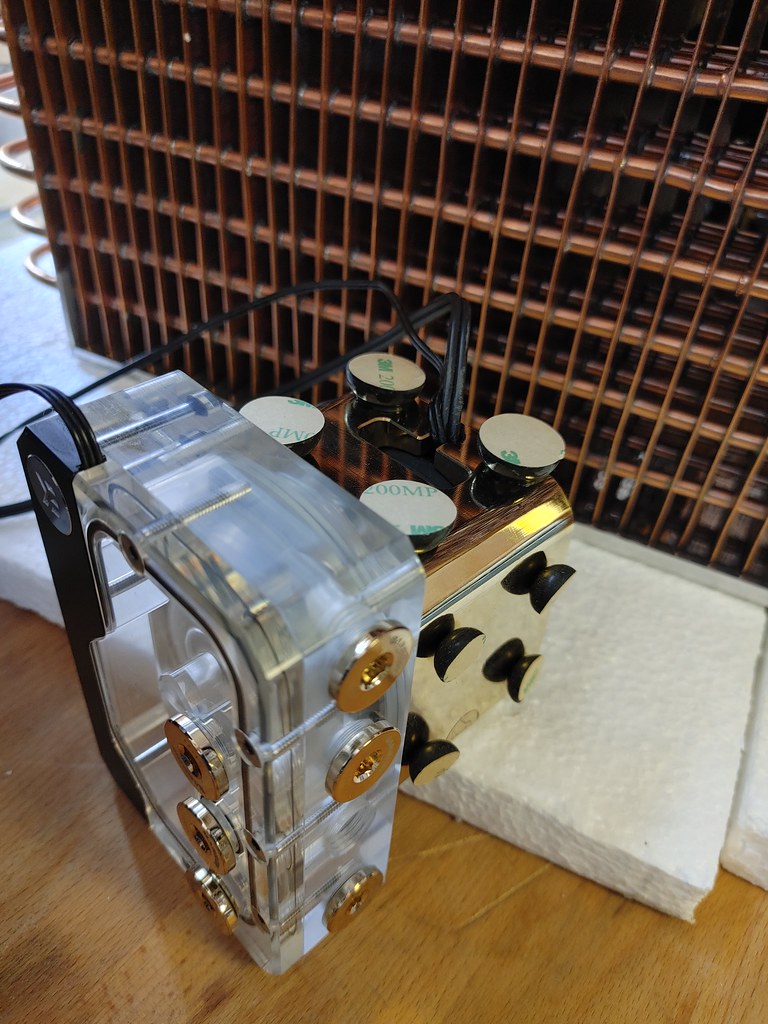 20230611_193756_HDR
 20230610_195019_HDR
 20230611_024732_HDR
 20230611_132132_HDR
 PSX_20230828_203027
 PSX_20230828_200029
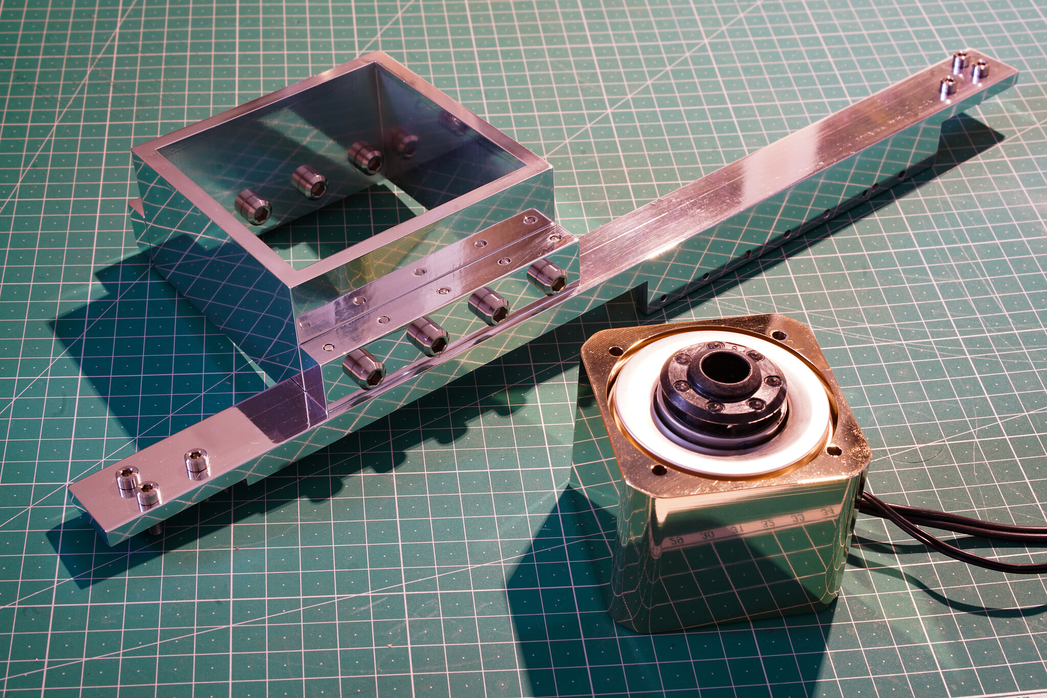 PSX_20230828_200655
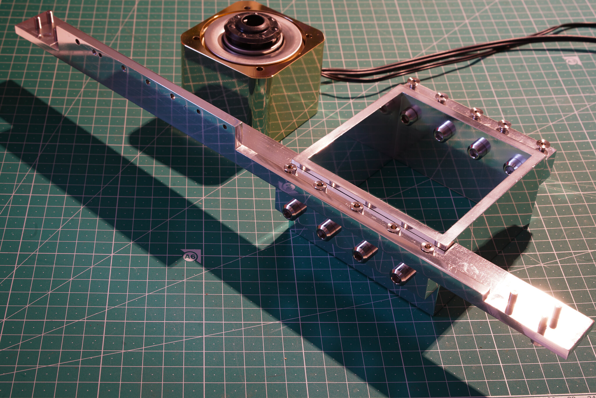 PSX_20230828_201535
 PSX_20230828_194725
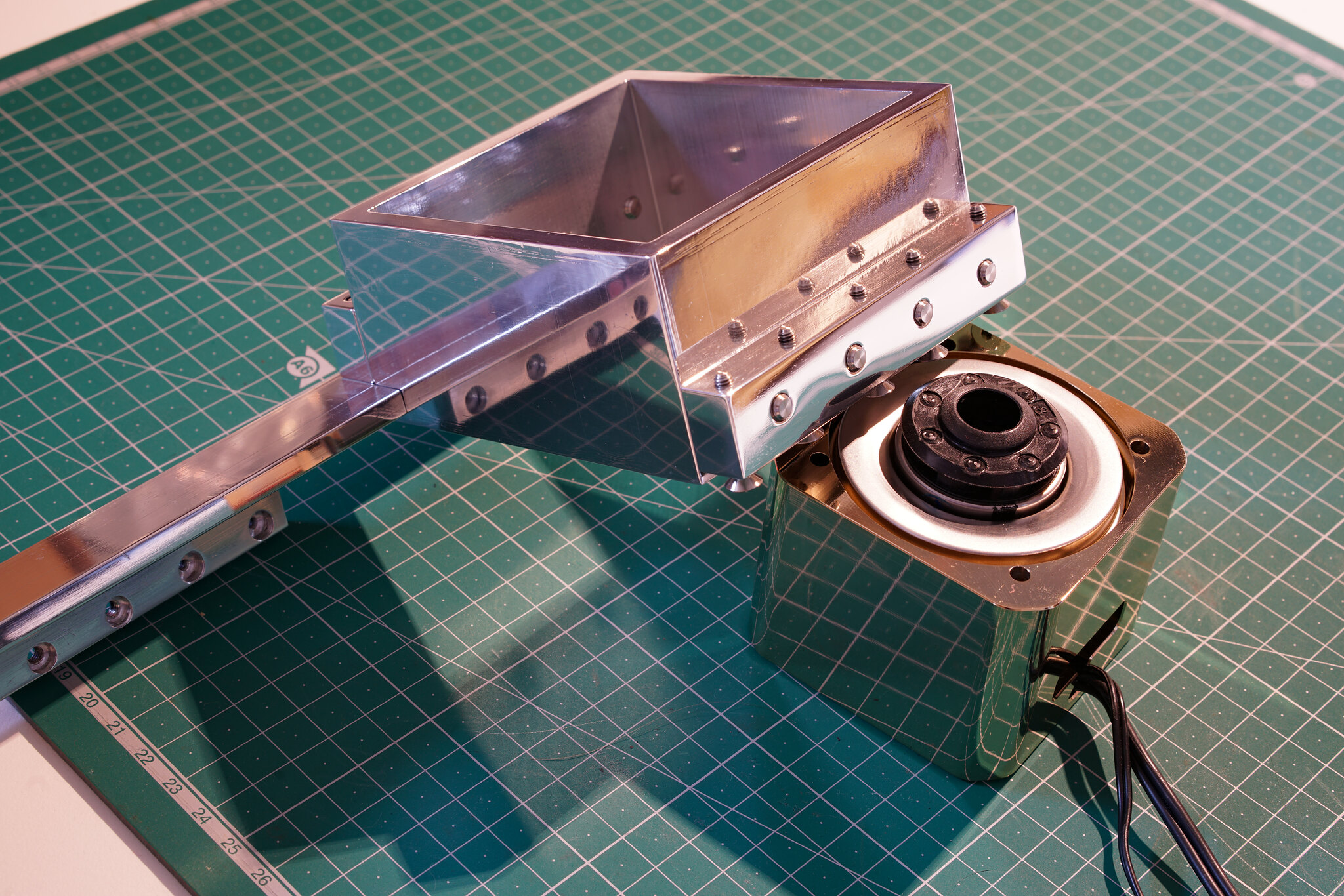 PSX_20230828_201906
 PSX_20230828_202517
 PSX_20230828_203545
")