OCUK Official IC Diamond/ Perihelion Test Results

Just back from vacation -WingZero30 I did get your CP results and will have processed next week currently battening down for a little tropical squall this weekend

Lost my home PC due to lightening strike(s) So a couple days reconfiguring all and should wrap this up test results next week.

Good to know you received the pattern. I hope the lightening strike incident wasn't too severe on your pc.

So WingZero30

Here is an EK water block CP impression whats your analysis?

http://forums.pureoverclock.com/sho...ond-Test-Results&p=82709&viewfull=1#post82709

Do you mean 'grumpydaddy' post 44?

If so I would like to say couple of things.

First of all I am not very much familiar with water blocks but it seems from his description, EK water block comes with 4 spring screws each capable of exerting 7-8kg of mass or 7.5kg (mean) x 9.81m/s^2 (g) = 73.575N = 73.575N x 0.2248lbf = 16.54lbf of force on CPU IHS.
So for 4 spring screws, 16.54lbf x 4 = 66.16lbf total force on Cpu IHS.

However it is likely that there will be some difference between the force that spring screws exert (after tightening them) and the force which Cpu IHS experiences, due to the design of mounting system. Best way would be to have sensor products analysis done.

Secondly he seems to be referring to CPU size as '37.5mm x 37.5mm' which I believe is the total size of the CPU, and not the size of IHS alone, which is likely to be different as measured in my previous post for my cpu.

He mentions:
This results in a pressure applied of 30.36lbs/psi

Pressure = Force / Area

He is actually incorrectly referring to Area here.

His waterblock C/P pattern seems to have some resemblance to my pattern in that more pressure is around the edges than in the centre. Retightning the screws seem to have yielded some further gain on the contact. Pressure seems to be good.

It is possible that either the water block or the Cpu IHS is slightly concave. Another possibility could be that both are near flat but mounting pressure tends to result in warping/flexing of motherboard hence affecting the contact slightly. :)
 
Last edited:
Good analysis pretty much working on the same contact pattern as you noted. The bowed bases whatever their advantages start with about 30% of the contact area by design and so more susceptible to secondary that influence in contact and pressure, unstable might be a better word so needs more detail to get just right.

img00092201108221846.jpg
rawimage.png


so back to figure 2 where heat has flow across the IHS. I should have several more WB impressions in the next couple of weeks and hope we can get some that have a better contact and we can define the limits,with a couple of curves, my guess it's a thin line.

HEATDAM2.png
 
Washer Modded Lapped Result

Thanks for emailing the results:). They are in my opinion very good results and huge improvement over previous contact/pressure results:cool:

I have rotated the image orientation based on previous results in which the upper and lower surface had more pressure. I think this would make sense as all the previous contact tests have given the same impression.


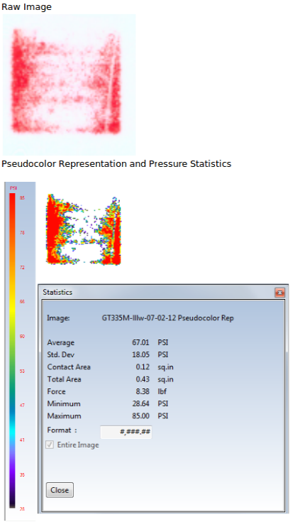
Raw Image

pic1bm.png


Pseudo Colour Representation and Pressure Statistics

Please resize image to a maximum 1024 pixels wide!


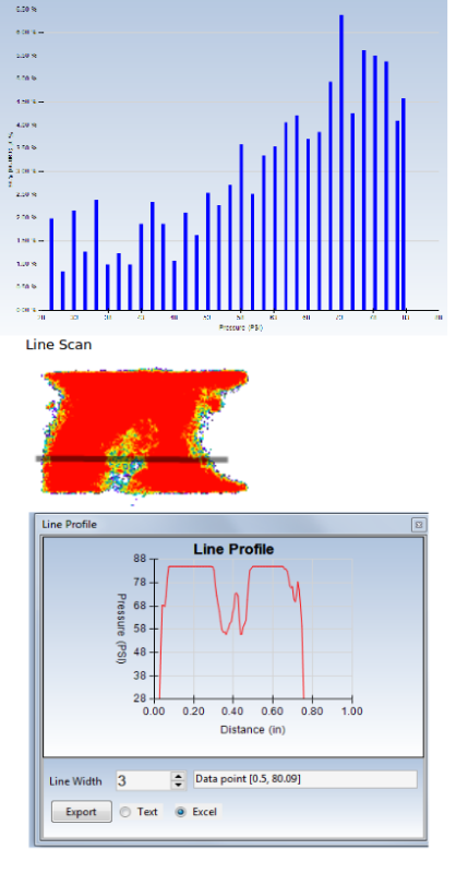
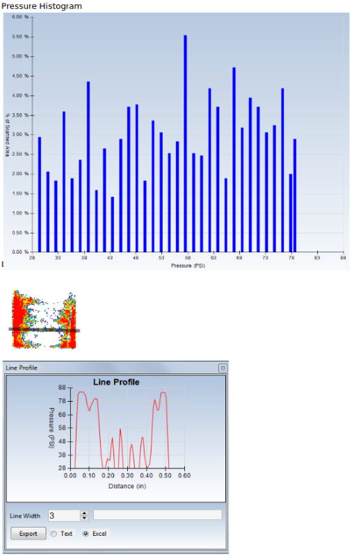
Pressure Histogram

Please resize image to a maximum 1024 pixels wide!


Line Scan

pic4oi.png


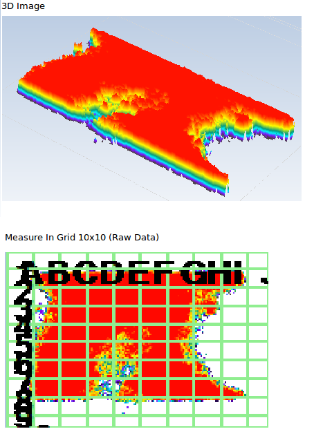
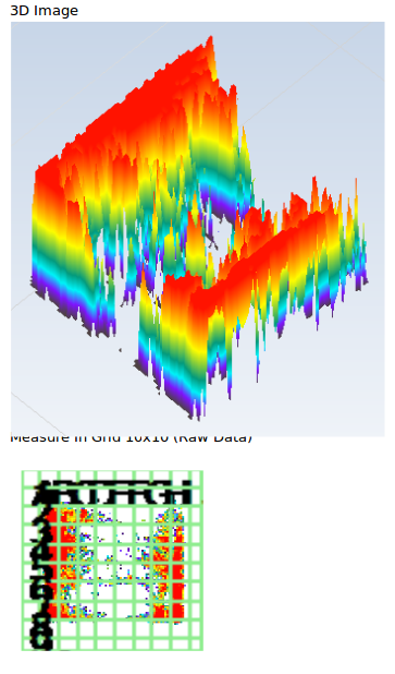
3D Image

pic5zh.png


Measure in Grid 10x10 (Raw Data)

pic6u.png


First of all looking at pressure statistics I am very glad that my calculated estimate of contact area is very close to the actual contact area of 0.97sq.in. Although there are anomaly contact impressions such as finger impressions, they shouldn't really affect the overall result as they are tiny and very few.

The rough measurement of the better pattern is 2.7cm x 2.3cm = 6.21cm^2 = 0.963 sq.in

Now in my case and as seen in earlier post, I found the total IHS area to be 1.215 sq.in:

I roughly measured Q6600 IHS (lapped square part that makes contact with heatsink) and it is 2.8cm x 2.8cm = 7.84cm^2 = 1.215 sq.in

In this regard overall contact is close to 80%.

However IC Diamond you stated the dims of 30mmx30mm. In that case overall IHS surface area will be 1.395sq.in.
So overall contact is close to 0.97/1.395 = 69.5% or 70% (round off)

So depending on the definition of IHS measurements, we are looking at the overall contact to be in the region of 70-80%. This I believe is excellent:)

Moving on, the overall average mounting pressure of 71.92PSI is again an excellent news. I was hoping that with all the previous efforts, the mounting pressure would atleast increase to 70PSI. Such difference from previous raw lapped mounting pressure of 53.58PSI.:)

The mounting force has also increased drastically to 69.56lbf (70 lbf round off) from previous results where for the raw lapped result, it was only 20.53lbf. So an increase of almost 50lbf!!:eek::cool:. I could definitely feel the resistive force of UNC spring screws.

From the pressure histogram it seems only about 27% of contact area is at 50PSI or below while the rest of contact area or 73% of it is at 50PSI and above.:)

The line scan, 3D image and grid pic all show that while the contact surface isn't perfectly smooth and hence some dips in pressure values across the surface, overall the pressure has increased significantly and in some regions reaching close to 80PSI+.

Again Contact/Pressure gets stronger as we move away from central position. As discussed previously I think the reasons why the pressure is weaker in central region is because:

1) The contact surface of both Cpu IHS and heatsink base is still not perfectly smooth. So we still have some areas of high and low regions. This suggests some further lapping preferably with belt sander.

2) As mounting force and pressure have increased drastically, this tends to warp the motherboard even though the bracket mounts and backplate movement has been 'fixed' or stopped. This was actually seen aswell once I fully tightened the IFX-14. However if this is good thing in increasing pressure, then so be it.

However looking at the 3D image, it is evident that mounting pressure in majority of central contact area is in the region of 66-85PSI. This is still very good.

To summarise:

contactpatternscomparis.png


Original Unlapped Pattern

-Average Mounting Pressure: 69.90PSI
-Contact Area: 0.55sq.in
-Mounting Force: 38.68lbf


Lapped Pattern

-Average Mounting Pressure: 53.58PSI
-Contact Area: 0.38sq.in
-Mounting Force: 20.53lbf


Washer Modded Lapped Pattern

-Average Mounting Pressure: 71.92PSI
-Contact Area: 0.97sq.in
-Mounting Force: 69.56lbf


All in all I am very glad with the latest results and with my PC system which has been able to facilitate improved contact/pressure/force. I think as an end-user it has been a magnificent experience learning about the whole process. Certainly as seen, to obtain the lapped pattern required several optimizations of the mounting system and this itself has been a challenging job. IFX-14 definitely has one of the least friendly mounting system and coupled with uneven Q6600 IHS, the cooling performce of my PC would have been severly restricted had I not learnt about improving the cooling further.

The thermal compounds can do rest of the job of filling in the uneven spaces. Of course with belt sander, results will improve certainly with regard to contact but that's for another day;):cool:
 
Finaly refitted cooler.

Before: Idle 21c 23c Playing game across 3 screens and watch video on TV 43c 45c
After : Idle 18c 20c Playing game across 3 screens and watch video on TV 35c 37c

Thank for the Ice Diamond. Looks like it is great stuff.
 
Been dealing with some health issues but back on track and putting together a final report which should be done in a day or two -My apologies for neglecting you people.
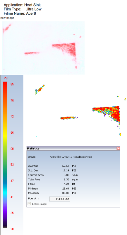
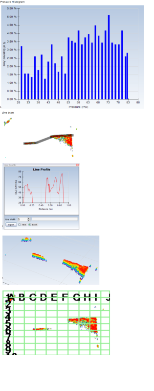
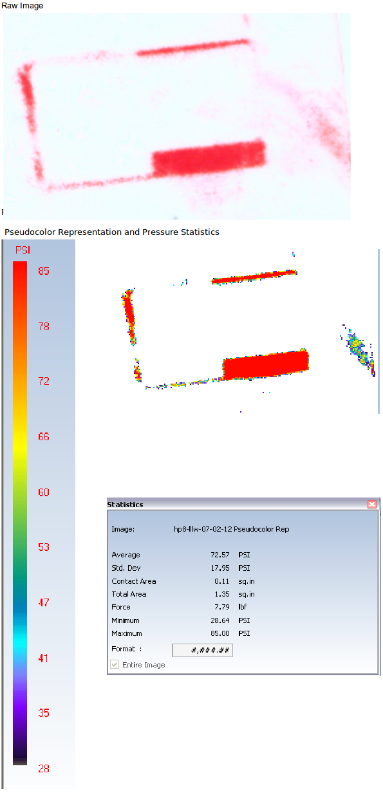
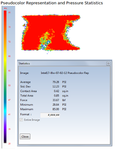
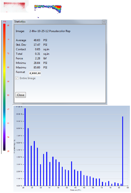
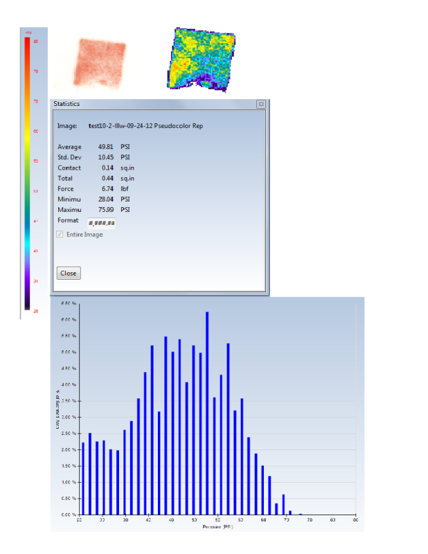
In any event some laptop Contact and Pressure images on a compound reliability study we are doing to pas the time - Little wonder that Notebooks see such high temps and compounds are subject to early failure, contact of only a few mm with 30 to 50W put the stresses in the soldering iron category

So out of the 5 CPU's Tested so far 4 are trending less than 50% contact which will greatly impact performance and long term reliability.

too456 Acer8

Acerrawimage.png

Acer83d.png
 
Last edited:
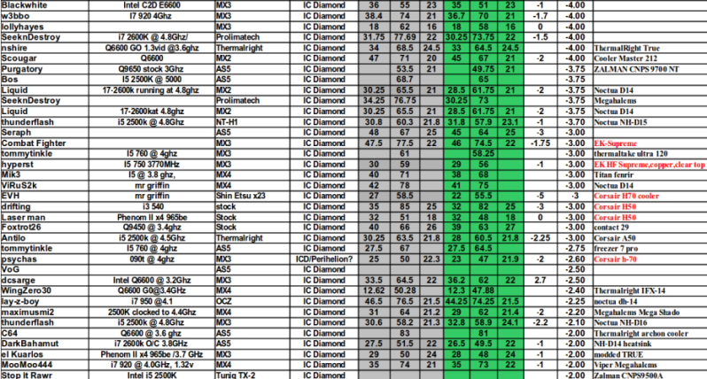
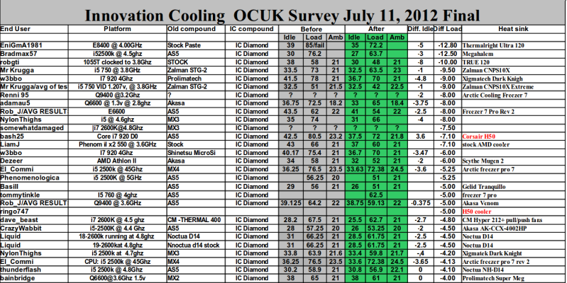
I will edit over the next couple of days breaking out the compounds as well as some observations on results- A lot of work went into this from all participants and is much appreciated here -

ocukfinaltable-2-1.png

ocukfinaltable-2-2.png

ocukfinaltable-2-3.png
 
Last edited:
For Comparison - I did not include all compounds as miscellaneous compounds tend to clutter the results and usually not noteworthy without a larger sampling.

AS 5 the most tested compound comprising about a quarter of our results runs about 2 C better than stock and the results here do not change much forum to forum. MX2 and MX3 nearly Identical in performance on this forum but does not match other forum results. MX4 half a degree better.

Shin Etsu did not test as well here as in other forums sample is not large so hard to tell (actually 17 end-user tests not 9 as posed above - typo on my part) The only thing about Shin Etsu could be perhaps it has a top recommended operating much less than most of the competitive compounds here (max 120C) so may not be as robust under heavy use found here.
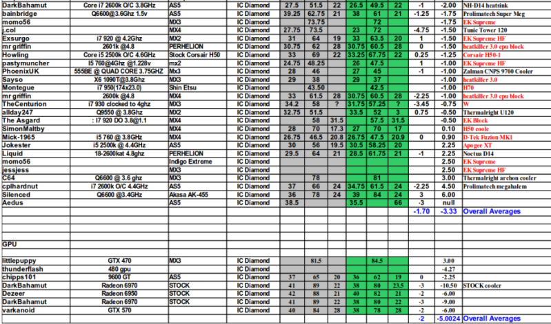
Indigo Extreme was a good performer here and the liquid metal in general are very competitive when tested some liquid metals (LTM) on our synthetic test bed we found it equal to a solder joint about a .04-05 C improvement over ICD.

OCUKCondenseResults-1.jpg


More later
 
Last edited:
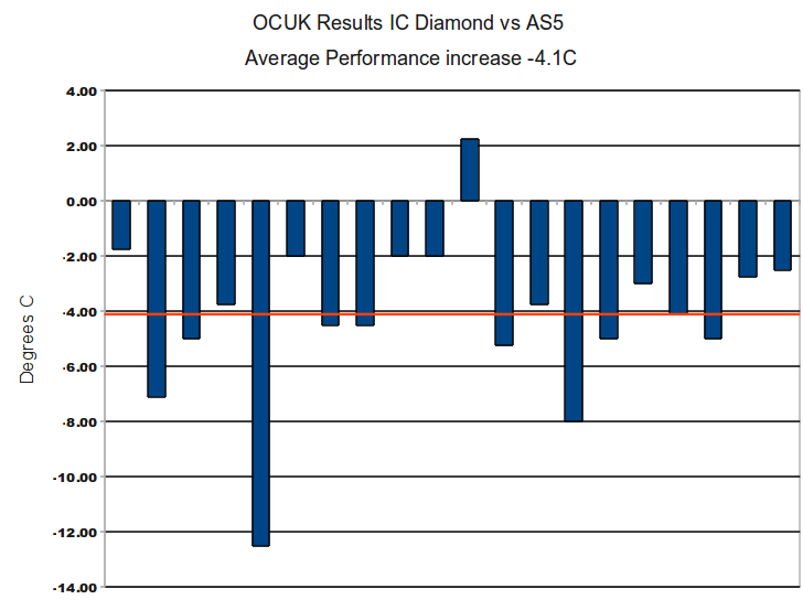
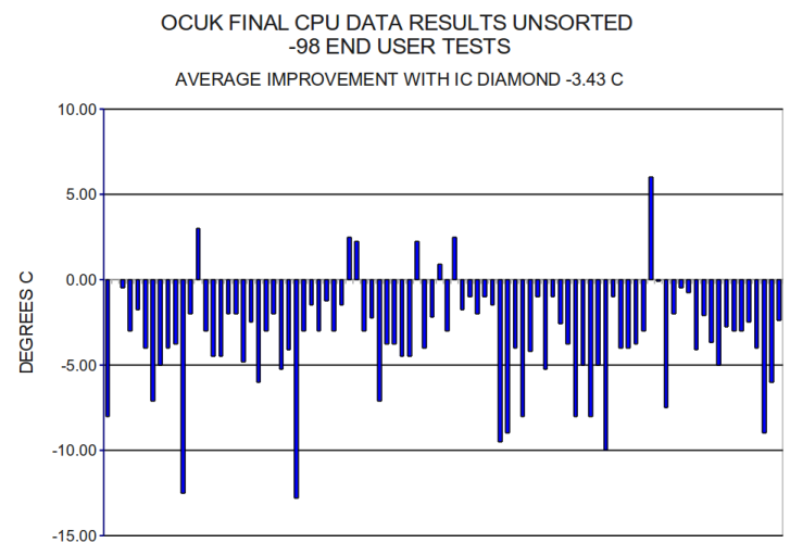
OCUK Thermal Compound Survey IC Diamond vs AS5 - 20 end user tests -4.1 C against our sampling of 197 endusers from 22 overclocking forums of -3.417 C, higher by 6/10th's of a degree.

OCUKICDvsAS5FINAL.png


AS5multiforumresultsdec302010.png


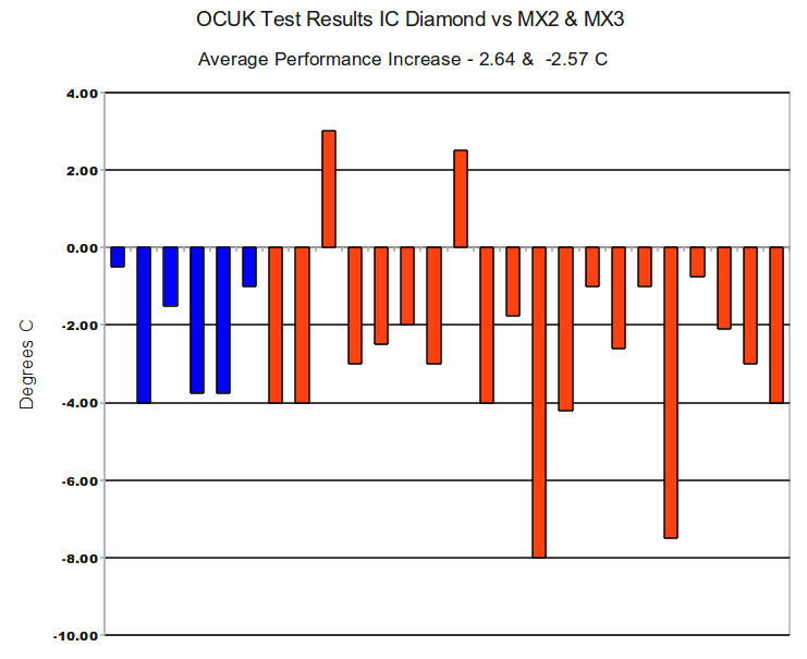
OCUK Thermal Compound Survey IC Diamond vs MX2 - 6 end user tests for MX2 with a reduction of -2.64C against our sampling of 48 endusers from 9 overclocking forums of -3.24 C, lower by 6/10th's of a degree.

IC Diamond vs MX3 - 19 end user tests for MX3 with a reduction of -2.57C against our sampling of 9 endusers from 2 overclocking forums of -2.94C, lower by 3/10th's of a degree.


OCUKICDvsMX2MX3FINAL.png


sept302010multiforumtestupdateICDiamond%20vs%20MX2MX3.PNG


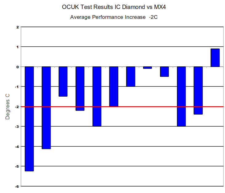
IC Diamond vs MX4 - 12 end user tests for MX3 with a reduction of -2.00 C OCUK . OCUK MX4 tests are the first in our data acquisition.

OCUKICDvsMX4FINAL.png


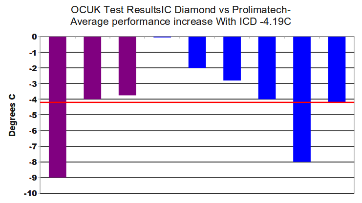
IC Diamond vs Prolimatech - OCUK only had 3 end user tests for Prolimatech So we combined with 6 other tests from 2 other forums for an average reduction of -4.19 C. - OCUK Test Results in purple

OCUKICDvsprolimatechFINAL.png


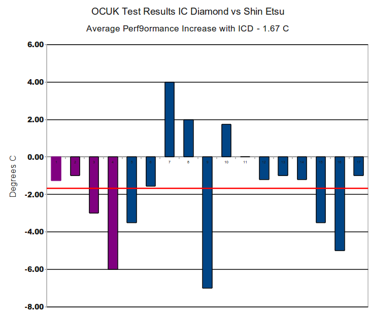
IC Diamond vs Shin Etsu - OCUK only had 4 end user tests for Prolimatech So we combined with 6 other tests from 5 other forums for an average reduction of -1.67 C. - OCUK Test Results in purple


OCUKICDvsShinEtsuFINAL.png
 
Last edited:
Fairly typical of what we see vs. stock compounds with an average improvement of -5.01 C

OCUKICDvsgpuSTOCKFINAL.png


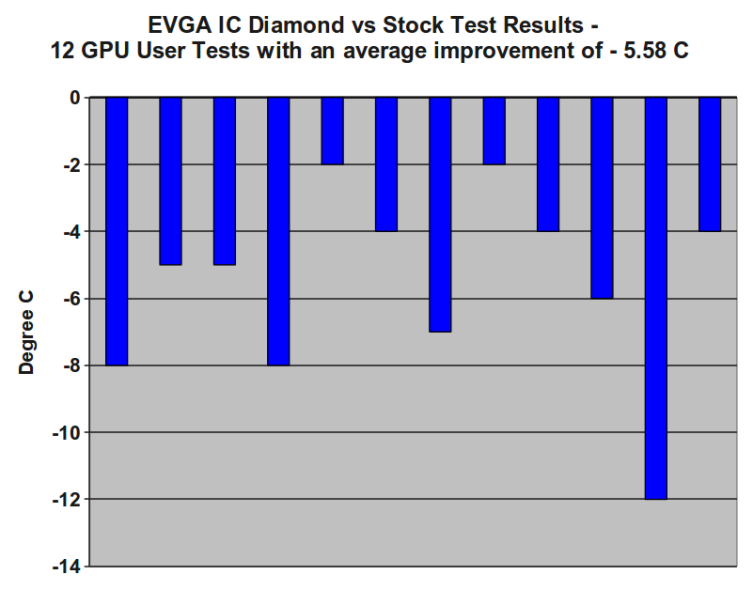
Here is a IC Diamond Vs Stock comparison that was done on EVGA with an average improvement of -5.58C

EVGAICDvsgpuSTOCKFINAL.png
 
Last edited:
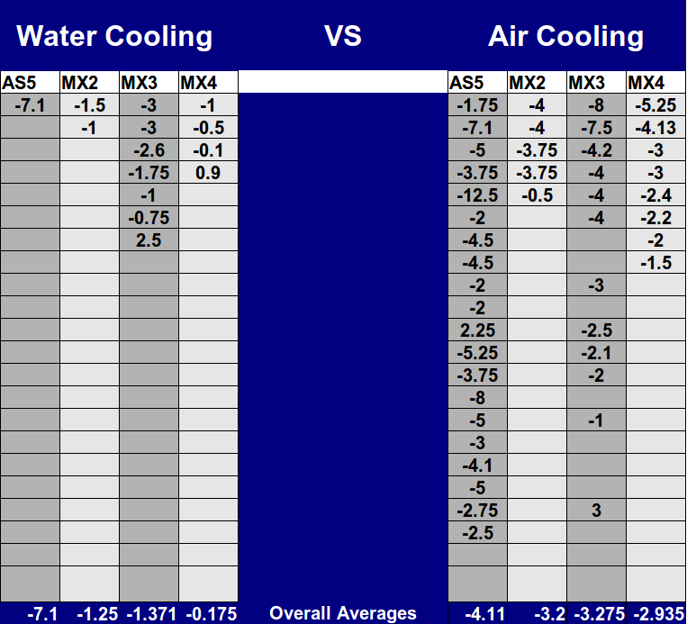
I thought this was an Interesting breakout of the numbers Delta' between compounds on the Water Cooling shrink considerably about 2C on the MX2 and MX3 and 2.75C on the MX4.

The only one cooler that bucked the trend was the Corsair and perhaps the EK block with better mounting schemes.


OCUKwatercoolingvsAircoolingfinalFINAL.png


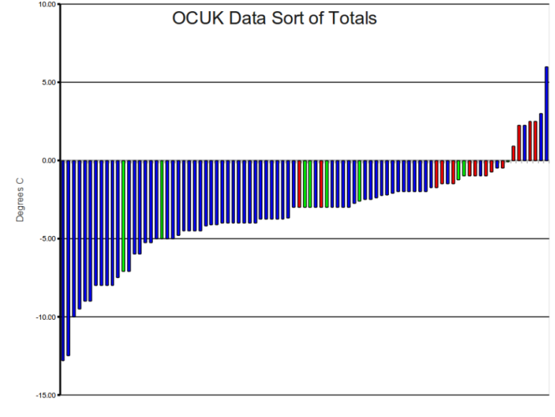
Below is a data sort of the test results The blue bars are air cooling all others are water cooling.

The Corsair results are marked in green and follow the usual distribution

OCUKDATASORTFINAL.png


More later
 
Last edited:
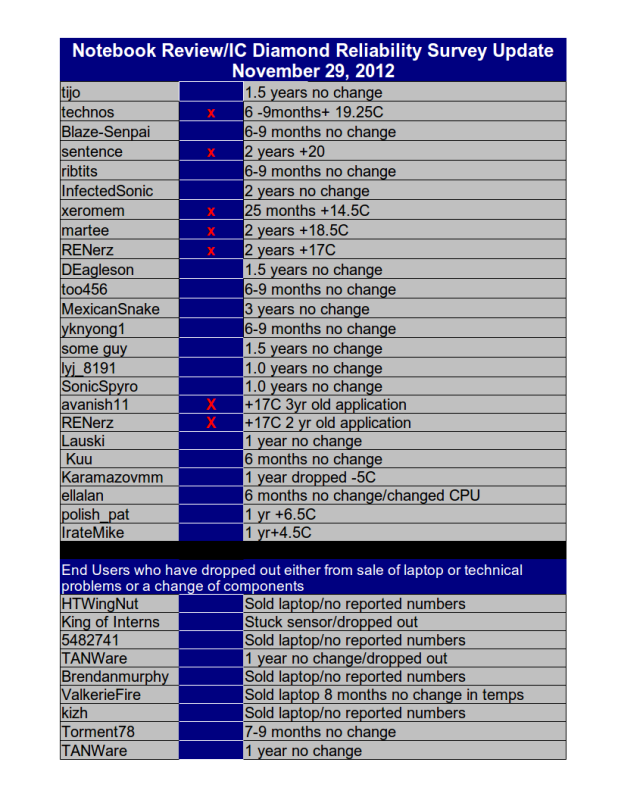
We have been doing a IC Diamond Reliability Survey over at Notebook Review with some interesting results, although only halfway through the survey a major factor in long term reliability relates to Contact and Pressure as we went through the process here with C/P and performance same applies to long term use.

When you have full contact with thermal and mechanical loads in sync with each other fully/evenly distributed across the entire processor and would be a likely canidate for long term use.


ICDIAMOND-NOTEBOOKREVIEWRELIABILITYSURVEYNOV292012UPDATE.png


Just some quick notes

Looking at the data to date it looks to be trending that if you hit a year with no change you are probably clear for extended 1.5- 2- 3 year use. A temp rise above +5C within the first year is a pretty good indicator that you will hit + 20C by year 2.

A kind of a go- no go indicator, those that hit in the 20C range I would call a failure and would repaste and while you have the system apart consider lapping the sink or some mod as TanWare's to improve contact. To note I have a couple of retailers that have agreed to test market the Contact and Pressure indicating film and should retail around $5-$8. Note that we are not selling the product and will not profit from it, we are only promoting it's general use for end users as a tool for improving performance/reliability

I am assuming a 5C +/- error on these tests as most are sloppy about reporting ambients.

As noted in my previous post there does not appear to be any correlation yet as to higher initial temps leading to a failure. Technos started with an initial temp of 58 C and at close to the one year mark ended up 19.25 C while Karamazovmm whose initial temp was 95C ended the year at 90C basically unchanged. There are other examples but this happens to be one of the more extreme. This was a suprise to me as typically notebooks runan average of 15C higher than the overclocked systems so I was expecting some indication in that direction at this point perhaps needs more time.

Applied thermal compound is simple stuff as things go, two mating surfaces with some goop in between and there are not too many avenues to explore to explain a difference in results other than amount of compound applied (we assume everbody gets this one right) Then the contact and pressure between the two joining surfaces.

As we discovered with the C/P testing the weak point in this simple setup is in the contact and is a reasonble cause for good result or bad result or something in between.

Note below yknyong1 contact area being worst case most of the heat transfer would be in the corner/edge area, a significat heat concentration more like a soldering Iron this edge corner/area would be the part of the joint to fail first and as the remaing paste is lightly contacted would then run at higher temps baking out initially then delaminating with further thermal cycling. This kind of contact is a likely canidate for early failure

the following BlazeSempai example at the other end is full contact with thermal and mechanical loads in sync with each other fully/evenly distributed across the entire processor and would be a likely canidate for long term use.

This is as simple as it gets.


yknyong1- Apple Macbook Air13 i5

2lllw.png


BlazeSempai p 8700

BlazeSempaip8700.png
 
Back
Top Bottom