OCUK Official IC Diamond/ Perihelion Test Results

Soldato
Joined
1 Jun 2010
Posts
7,053
Location
London
Much better contact and pressure

I tried both washers. The smaller washer with 3mm thickness just didn't cut it with the IFX-14 mounting system.
Placing it underneath the mounting plate, and securing the plate at one end slightly by giving the UNC screw one or two turn at that end meant the distance significantly increased between the bottom of UNC screw and hollow pillar on the other end.

This required enormous downward force on the other end in order to try to secure the 2nd UNC screw into the hollow pillar and even then it proved impossible and I just had to abandon the smaller washer as I was afraid of damaging cpu/socket pins.

Better to be safe than sorry!!;)

On the other hand the larger washer proved to be a very good companion for IFX-14 mounting system and infact I am already using it as I am typing this post:cool:

The following pics give a better story!!

imag0236u.jpg


imag0238g.jpg


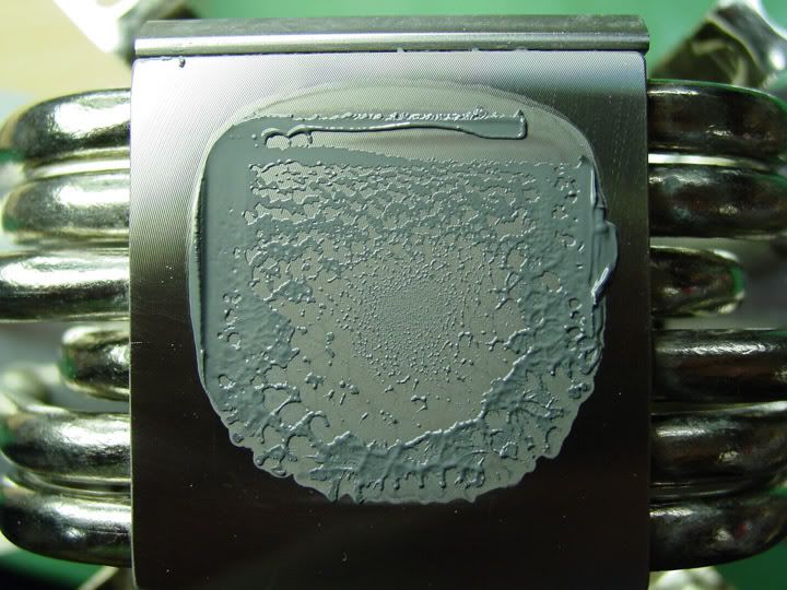
Here are the pressure and contact patterns!!:cool:

Although I am not sure why there is a slight peculiar missing contact or contact gap at the bottom

imag0239s.jpg


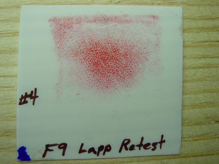
I then decided to turn IFX-14 the other way round and repeated contact and pressure test and voila!!

imag0240r.jpg


What a difference from unlapped contact!!:D

Ofcourse the pics don't show the patterns as well, as shiny surface of the paper means some reflection. Plus this is all hand lapping as I can't afford belt sander being a student:(. So the overall lapping results won't be on par with belt sander results. Also bearing in mind that Q6600 cores reside in the upper half of the IHS as discussed previously.

However one thing I have noticed is that my washer modded lapped contact and pressure patterns seem to resemble the data point 10 pattern more or less on IC website:


http://www.innovationcooling.com/ICDtroublshooting.htm

datapoint10.png


So IC Diamond, what do you make of it? :)
 
Last edited:
Associate
OP
Joined
7 Dec 2010
Posts
223
Sensor products introduced a new paper this year so you should compare to the OCUK review sample. A little different than the older stuff so I am not always sure what I am looking at on a screen shot. May be the light or camera but the first test looks better than the second deeper red (higher pressure) + more contact area.

Pressure does dominate as increased pressure increased contact into a more defined pattern than pre washer raw image.

Looking at he two impressions looks like the hardware has a slight bias to heavier on the left and a little light on the right. Might rotate the bracket to see if it corrects.

rawimga.jpg
statisticsa.jpg

lapping2.png
imag0239s.jpg
 
Soldato
Joined
1 Jun 2010
Posts
7,053
Location
London
Sensor products introduced a new paper this year so you should compare to the OCUK review sample. A little different than the older stuff so I am not always sure what I am looking at on a screen shot. May be the light or camera but the first test looks better than the second deeper red (higher pressure) + more contact area.

Pressure does dominate as increased pressure increased contact into a more defined pattern than pre washer raw image.

Looking at he two impressions looks like the hardware has a slight bias to heavier on the left and a little light on the right. Might rotate the bracket to see if it corrects.

Do you mean I should change around the bracket mounts?

I usually secure mounting plate on the left first by turning the UNC screws once or twice into bracket mount hole after having lowered the mounting plate slightly. This is easier for me as I don't have to deal with northbridge heatsink coming in the way.

However as seen in pic below and as stated in previous post, the mounting plate lifts up on the other side. In order to bring it down I have to apply more pressure and this means that left part of IHS gets pressurised may be more than the right side?

ifx14washermounting.png


If I don't lower the mounting plate on either side initially for inserting of UNC screws into bracket mount holes, then I simply can't insert the screw as with the addition of washer, the distance has increased further between the bottom of UNC screw and bracket mount hole.

Although I would have thought that contact paper would adjust for overall profile of the base bottom.

Do you think it is worth giving it a try if I secure the mounting plate on the right first?
 
Associate
OP
Joined
7 Dec 2010
Posts
223
Perhaps it is the silly season and parsing things to a too fine detail.

May or may not make a difference you are down to things like perhaps the mother board is a little thicker in one side or the stamped and bent brackets between the two ends are off .010 - Tolerance on this stuff is probably +/- .005 and with some tolerance stacking in the assembly, my guess it's pretty hit or miss whether you get an almost perfect contact like the OCUK review lapping job above or some unbalancing where one side might have 80 PSI and the other side 40 psi or even "0.0" psi

You could try a shim on the high side, maybe a piece of duct tape would do it.

all in all you have a pretty broad contact pattern which compensates a lot for misalignments even if the sink is a few thousandths higher on one end than the other.

It is more of an issue perhaps in cases like the bowed water blocks which start with a narrow contact area on center (<50%? of IHS contact area ) to begin with so along the contact axis only maybe 1/4 of the the IHS on one side would be would be in full contact with the sink so the setup would be pretty well thermally choked.

My guess is you would see an unbalance to some extent in most bowed configurations.
 
Last edited:
Soldato
Joined
31 Dec 2007
Posts
13,616
Location
The TARDIS, Wakefield, UK
Point of View GTX 570 Standard Cooler

GPU 800mhz
Shader Clock 1600mhz
Memory 1950mhz (3900mhz)
Voltage 1025mV


Before Compound:
Ambient Temp:28c
Idle Temp:40c
Load Temp:84c

ICD 24ct
Ambient Temp:28c
Idle Temp:38c
Load Temp:78c

Load temp was taken after first using 3d Mark 11, 3d Mark Vantage, Heaven Benchmark then about an hours play of Just Cause 2

Intend to replace cooler on 570 so be interesting to see what I get after that.
 
Soldato
Joined
1 Jun 2010
Posts
7,053
Location
London
Perhaps it is the silly season and parsing things to a too fine detail.

May or may not make a difference you are down to things like perhaps the mother board is a little thicker in one side or the stamped and bent brackets between the two ends are off .010 - Tolerance on this stuff is probably +/- .005 and with some tolerance stacking in the assembly, my guess it's pretty hit or miss whether you get an almost perfect contact like the OCUK review lapping job above or some unbalancing where one side might have 80 PSI and the other side 40 psi or even "0.0" psi

You could try a shim on the high side, maybe a piece of duct tape would do it.

all in all you have a pretty broad contact pattern which compensates a lot for misalignments even if the sink is a few thousandths higher on one end than the other.

It is more of an issue perhaps in cases like the bowed water blocks which start with a narrow contact area on center (<50%? of IHS contact area ) to begin with so along the contact axis only maybe 1/4 of the the IHS on one side would be would be in full contact with the sink so the setup would be pretty well thermally choked.

My guess is you would see an unbalance to some extent in most bowed configurations.

It's amazing that when talking about precision in computer cooling, that even a 100th of a mm can make so much difference. No wonder micrometer and the likes were invented to measure such tiny measurements.

Even I think that motherboard PCB isn't uniform in it's thickness. I also noticed that while having motherboard on a flat table, it was straight around cpu area as there is back plate underneath it.
As you further went towards southbridge chipset and PCI slots, it tended to sag or bow.

Also I do get the sense that bracket mounts won't be 100% aligned at the same position level. It may be the case that one bracket mount is slightly higher than the other coupled with imprecise heatsink base profile.

The heatsink bottom profile won't be 100% flat either as noted even from lapped pattern where there were areas of high pressure and areas of low pressure. Same goes for CPU IHS.

I think it is probably for these reasons thermal compounds have been in use as there is full agreement that because there remain gaps between heatsink and cpu, the thermal compounds act to fill those voids or gaps leading to better heat transfer.

I could try raising the bracket mount on the left side or simply switch around the bracket and then initially secure the mounting plate from right side and see if that makes any difference.

I think we are at the point where we are talking less than a mm or a fraction of mm as you said.
Also as an end user I think fundamental possibilities have been explored such as lapping and placement of washer for increasing contact and pressure. Although there is always room for further improvement but I think I am at the limit of what I can do with my setup any further.

It would be interesting to know how OcUK managed to get such fine contact pattern and this includes over 80lbf of mounting force. Perhaps their setup with different factors may have yielded better results or they made use of better equipment perhaps belt sander.

Perhaps this is fundamental characteristic of experimental investigation that nothing is perfect, everything is approximate.

Although it has been noted now that the more precise we want to be the more factors we have to try to control and take out of equation.

All in all I am glad that washer and lapping improved contact and pressure overall even if things aren't perfect considering unlapped mounting results.:cool:
 
Last edited:
Soldato
Joined
1 Jun 2010
Posts
7,053
Location
London
Getting there!!

Ok first of all I disassembled the IFX-14 mounting system.

-Turned the 'Back plate' 90 degree anti-clockwise as it is symmetrical and then placed it underneath the motherboard again

- Swapped around the 'Bracket mounts and then tightened them fully onto back plate

-Created 6 outline shapes of the washer by placing the washer on an A4 printing paper and drawing the outer and inner circular diameter as seen below. :

imag0246i.jpg


-The shapes were then cut out and two of the 'Full' shapes were joined with super glue and placed on washer. Then two additional full shapes were taken and folded in half to form semi circle and joined with super glue again. The 'paper shape' can be seen below. I would call the paper shape 'shim' from now on

imag0247z.jpg


-The semi circle shapes were then joined to full shapes with super glue in order to form shim. This can be seen below:

imag0245v.jpg


-IFX-14 was then placed on top of contact paper. Then washer was placed on the IFX-14 base. This was followed by the 'shim' which was placed on top of washer with the semi-circular region being on the right where the contact was found to be less in order to compensate for the slack .

(Note: I still couldn't initially secure the mounting plate on the right first when exerting pressure on the left side as northbridge heatsink became a major hurdle. So again decided to initially place the UNC screw on the left first and then applied more pressure on the right side and placed 2nd UNC screw into bracket mount hole)

imag0243i.jpg


-The difference is impressive!!!:eek::):cool:
The right side has improved immensely albeit with slight decrease in contact on the centre-left. This is most probably due to semi-circular shapes on the shim facilitating extra contact and pressure on the right:)

imag0244z.jpg


-In order to compensate for this and to provide balance, the last two shapes were then folded into semi-circles aswell and joined on the other side of the 'shim'. Now the surface level of the shim is balanced:

imag0248x.jpg


-Carried out the testing again with final contact paper as two others were wasted with 3mm washer. However as seen for some reason it didn't make good contact. I used this contact paper early on when testing larger washer on it's own. Even then it didn't make any contact. So decided to use it for this part and still disappointing!!:mad:

imag0250ar.jpg


-Unfortunately I don't have any more contact paper as I have run out:o.

IC Diamond will you be kind enough to send me some more as I really want to test the 'balanced shim'. I do hope that balanced shim will provide the best contact!!:cool:

In the mean time I am impressed!!:D
I can definitely feel that turning the UNC screws fully require greater torque or turning force:cool:
Btw I am using shim along with washer as I type this :cool:

imag0249p.jpg
 
Last edited:
Associate
OP
Joined
7 Dec 2010
Posts
223
I'll send some more - nontrivial as they say..

I am thinking there must be a poor man's way of doing this - maybe carbon paper between two pieces of paper

or

a rubbing impression like they do on old gravestones

or

Perhaps a colored wax - turn the machine on for a minute low spots would be colored and high or contact areas would have a clear translucent glaze.

You have done a few of these tests and you can transfer that experience by observing paste impressions and comparing them to the sensor product prints - take some pictures then compare much in common just a little different view of it.

Take a cheap compound and do a few mounts, optimize it some more while you are waiting for the paper.
 
Associate
OP
Joined
7 Dec 2010
Posts
223
Reading paste impressions

Paste impressions:

Poor mounting pressure

img5700ip1.jpg


good mounting pressure - difference between mounts -6 C - light glaze

img5704wb3.jpg


Another example - Contact paper sample with paste impression of the same mount

attachment.php
 
Soldato
Joined
1 Jun 2010
Posts
7,053
Location
London
I'll send some more - nontrivial as they say..

I am thinking there must be a poor man's way of doing this - maybe carbon paper between two pieces of paper

or

a rubbing impression like they do on old gravestones

or

Perhaps a colored wax - turn the machine on for a minute low spots would be colored and high or contact areas would have a clear translucent glaze.

You have done a few of these tests and you can transfer that experience by observing paste impressions and comparing them to the sensor product prints - take some pictures then compare much in common just a little different view of it.

Take a cheap compound and do a few mounts, optimize it some more while you are waiting for the paper.

Yeah I do get a feeling that I may need to add 1-3 more paper cut outs of the washer shape on top of the shim in order to further enhance the contact
 
Associate
Joined
9 May 2011
Posts
40
Location
Doncaster
Ok so I bought some ICD-7 to give it a try, and without any curing time at all on the ICD, the results for comparison are below.

This is with AS5
57AF34E8_temps.jpg


And this is with ICD
27716A22_temps_icd.jpg


Heatsink is Titan Fenrir Evo, applied paste both times using pea blob, Don't find it necessary to prepare the base of the titan as it's almost perfect.
 
Associate
Joined
4 Oct 2006
Posts
736
Location
Vauxhall London
Applied the ICD 24 and gave it a week to settle in and did some testing today.

Core i7 2600k O/C 4.4GHz @ 1.328vcore (1.6GHz @ 0.900vcore idle) - Prolimatech megahalem heatsink/ with 2 push pull fans. Thermaltake armor tower case. Ran prime 95 for 1hour on the blend setting.

Arctic Silver 5:
Ambient: 24.0C
Idle: 37C (37,36,37,38)
Load: 66C (66, 67, 66, 65)

ICD:
Ambient: 24.0C
Idle: 33.75c (32, 34, 35, 34)
Load: 61.5c (58, 63, 63, 62)
 
Soldato
Joined
12 Jun 2007
Posts
8,737
Location
Ireland
just arrived 24 carat one , took 1 month to arrive almost gave up on it , will pick mx-3 on Wednesday will start testing then.

edit: 1090t @ 4ghz 1.4125 vcore in bios , Corsair h-70 Apache blacks push & pull , case antec 902 , should i read core temps or cpu temps ? i try reapply again maybe i did something wrong will do gpu later

Before Compound: Arctic mx-3
Ambient Temp: 22.3 c
Idle Temp: 25 c
Load Temp: 50 c

ICD/Perihelion
Ambient Temp: 21.9 c
Idle Temp: 23 c
Load Temp: 47 c
 
Last edited:
Associate
OP
Joined
7 Dec 2010
Posts
223
just arrived 24 carat one , took 1 month to arrive almost gave up on it , will pick mx-3 on Wednesday will start testing then.

edit: 1090t @ 4ghz 1.4125 vcore in bios , Corsair h-70 Apache blacks push & pull , case antec 902 , should i read core temps or cpu temps ? i try reapply again maybe i did something wrong will do gpu later

Before Compound: Arctic mx-3
Ambient Temp: 22.3 c
Idle Temp: 25 c
Load Temp: 50 c

ICD/Perihelion
Ambient Temp: 21.9 c
Idle Temp: 23 c
Load Temp: 47 c


3 10th's of a degree off the average more or less, as these things go pretty good effort - thanks for taking the time to test

sept302010multiforumtestupdateICDiamond%20vs%20MX2MX3.PNG
 
Last edited:
Back
Top Bottom