[Project] Out of Reach

Soldato
Joined
31 May 2006
Posts
7,564
Location
West London
Project log: Out of Reach

Reason: Primarily to move pc ‘out of reach’ of my little boy and secondary to provide an area that I can actually work at home from
(cutting down my office hours and getting home for my sons bedtime)

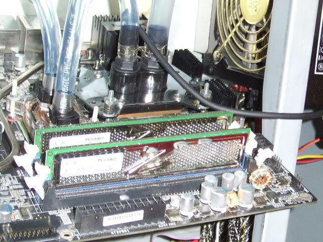
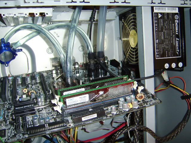
To cut a long story short the PC is now in our bedroom with a bungee HDD mod and a passive watercooling loop to remove almost all the fans and noise from the system. I’ll give you all the pre-mod guided tour later so you can see what I’m working with. It on 24/7 working on a DC project called Folding@Home and runs so quietly that I can hear my son breathing in the room next door at night. :D

To stop my little one ‘playing’ with the buttons (especially the power one) a barricade has been setup at the foot of our bed so he can’t walk round. He also knows that he’s not allowed to climb off that side of the bed, and thankfully rarely does.

Current setup technically works reasonable well considering is going something akin to prime 24/7 at 42c (with a 7300 in the loop). The passive rad could be moved further away from the central heating radiator. But it only comes on when very cold outside so not a major problem day to day. The major issue is comfort, as sitting on the bed is the only way to use the PC – fine for surfing for up to 30 minutes but not great for work.

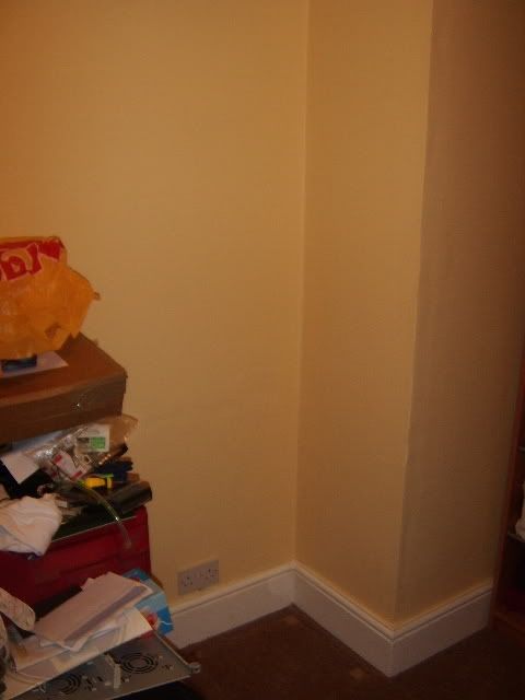
Original starting point:

desk.jpg

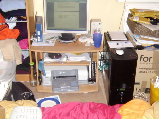
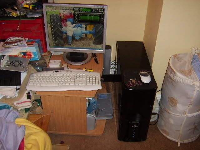
The corner of my bedroom, with pc occupying/surrounding an old TV bench.

behind.jpg

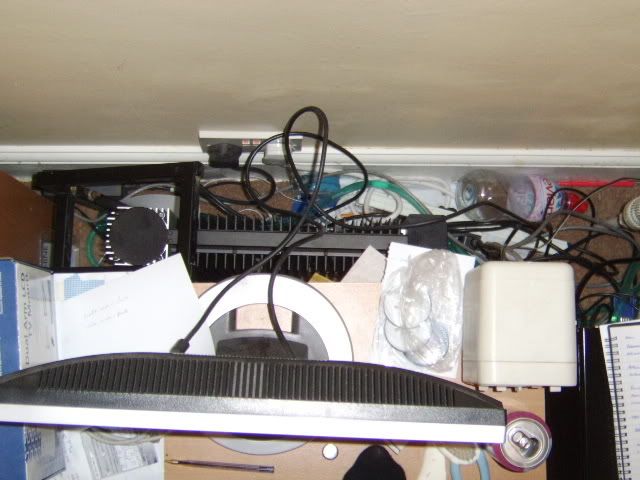
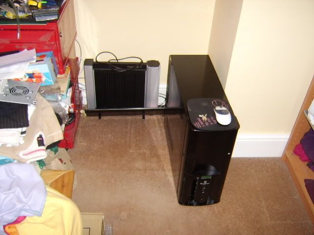
Revenge of the spaghetti monster, well if it’s out of sight…;)

Caseinside.jpg

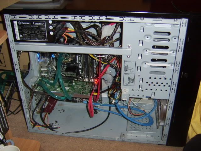
Not the neatest case in the world I’m sure you’ll all agree
but since I removed the fans I’ve been a bit slack. :o

Full specification:

Case: Silverstone TJ05 with thermal controller (windowed side panel still boxed)
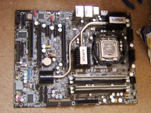
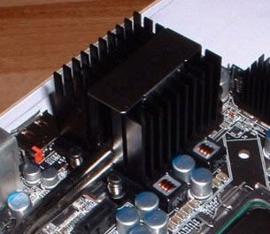
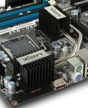
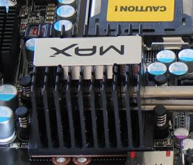
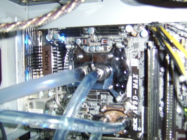
Mobo: Abit AW9D-Max running at FSB360
CPU: Intel [email protected]
Ram: OCZ PC2-6400C4 Dual Channel Platinum Revision 2 XTC 1:1@760 (4,4,4,16)
VGA: Geforce 7300 SE passive
PSU: Enermax Liberty 400w
HDD: Western Digital raptor 36Gb
HDD: Seagate 300Gb
Drive: Pionoieer DVD-RW.
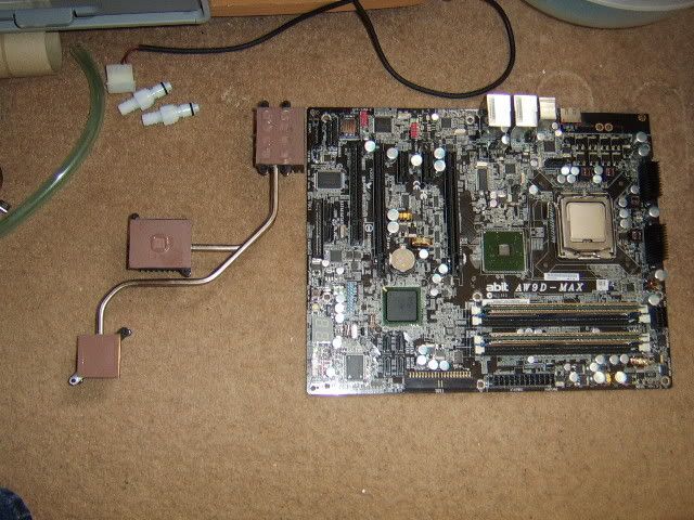
CPU Block: Zalman ZM-WB4 Gold
VGA Block: Zalman ZM-GWB3
Reservoir: Reserator2 body
Radiator: Reserator2 body
Pump: 3w DC12v 150L/sec (Lift 1m) inc in Reserator2 body


Even with what many consider a weedie pump this loop keeps both my CPU cores at or below 42c (coretemp)
at full load with the 7300 on the same loop. None to shabbly I’m sure you’ll agree for a system that relies on
natural convection in a house at 20c.

For comparison here's a few coretemps values for the chips I've had cooled by the Reverator in the last month or so.

[email protected]@100%@42c - Thermalright xp120 and Amber at 7v’s (plus 2 case fans)
[email protected]@100%@52c - Zalman Reserator2
[email protected]@100%@43c - Zalman Reserator2
[email protected]@ 75%@70c - Zalman Reserator2
[email protected]@100%@42c - Zalman Reserator2
[email protected]@100%@54c - Zalman Reserator2 with 7800GT OC installed

screenie.jpg

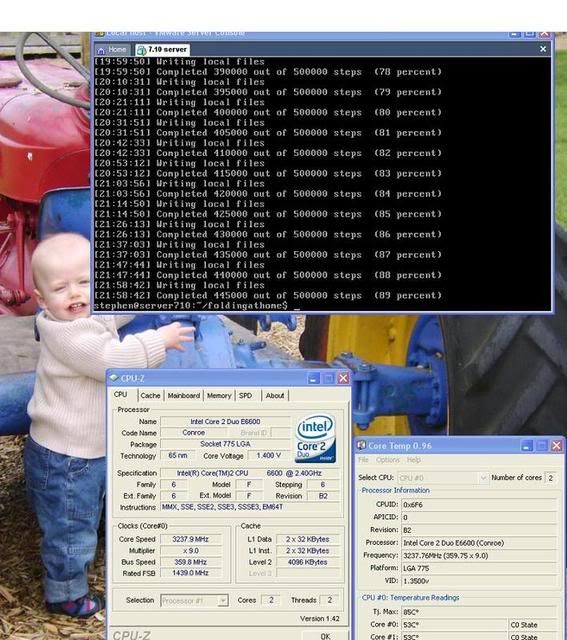
Screenshot of F@H coretemp and CPU-z, wallpaper is the little one in question :D

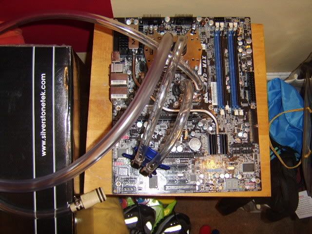
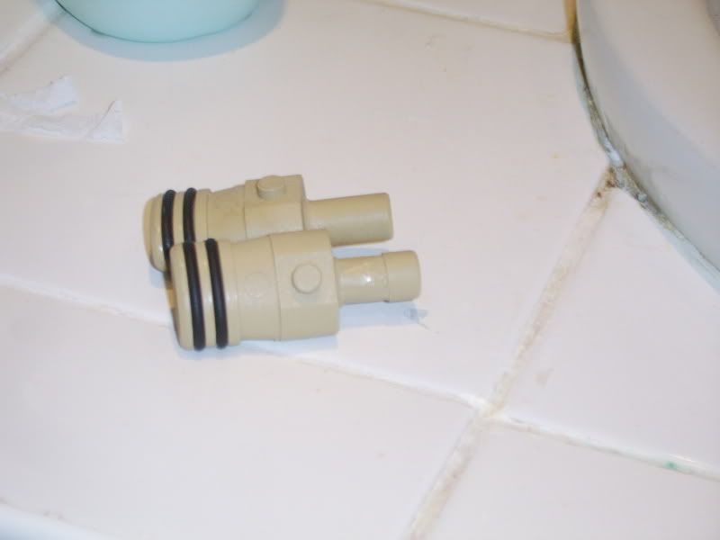
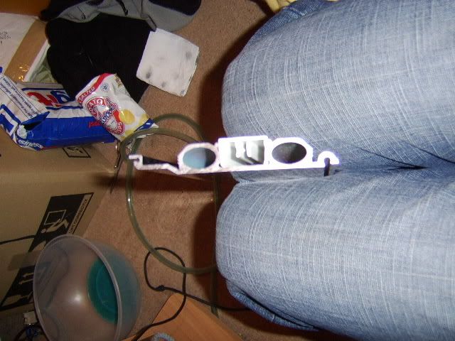
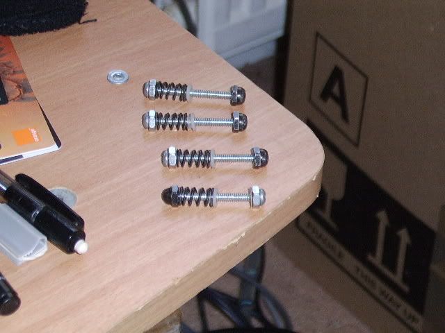
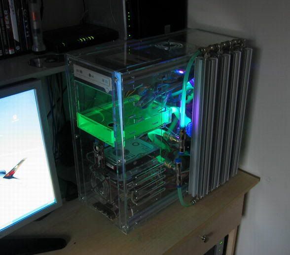
Ok that’s where I was, now for a sneek peak as some of the parts for the build.
There's a few missing but I'll intro them later as I progress.

bits.jpg


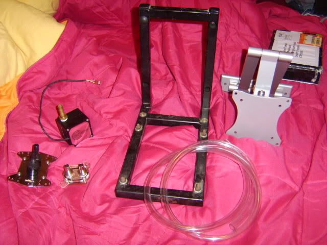
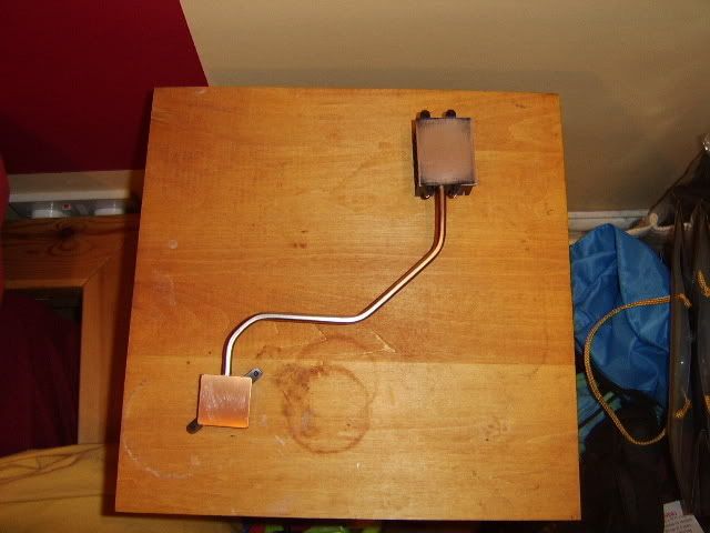
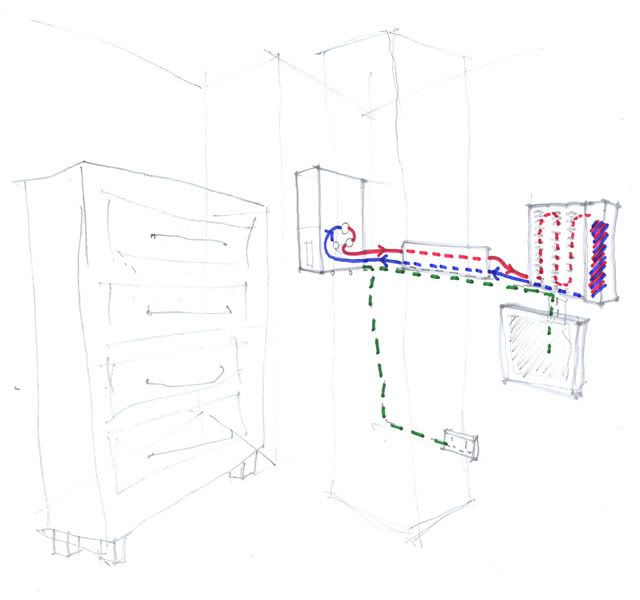
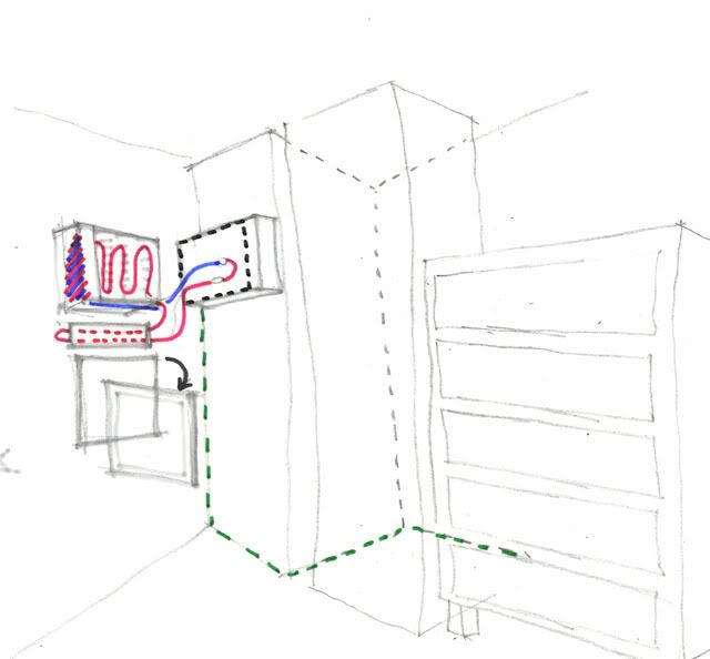
Edit: OK I know I haven't even started yet - but had a major re-design last weekend that resulted in me needed a different shaped case.
But have no fear I'm collecting it Wednesday and the grand plan will be revealed.
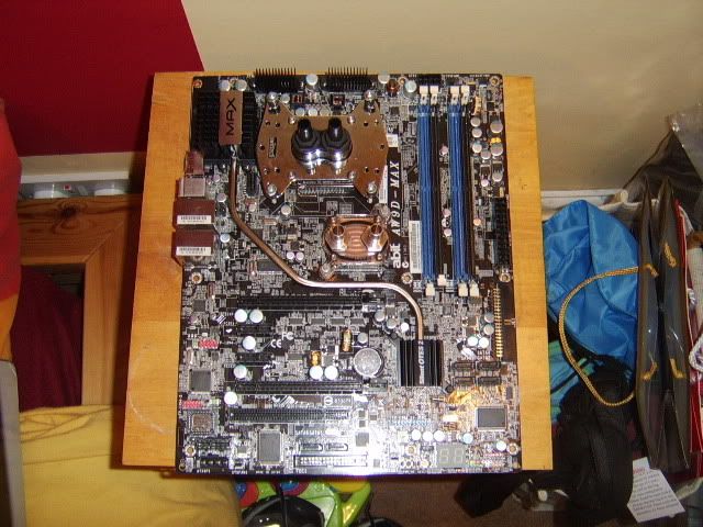
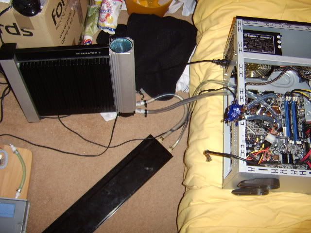
Prior to that I'll show all my ‘Plan A’ and the major flaw that my wife spotted
(I was to pre-occupied with aesthetic to notice I removed maintenance access Doh!)
 
Last edited:
Soldato
OP
Joined
31 May 2006
Posts
7,564
Location
West London
Plan A:

PlanA.jpg

Plan A Sketch layout - colour key: Red – hot water, Blue – Cool water, Green – power / data

I was planning on mounting my TJ05 on the wall return, moving the single wardrobe 250mm to the right.
The wardrobe would then hid most of the cabling to the case and I’d route the water cooling loop via the
new passive radiator into the Reserator2.The new rad also has an integrated cable duct to keep the
monitor / Reserator wires neat and hidden. The screen would then be mounted on a double hinge arm
below for viewing from the bed or from a shallow desk and chair directly in front.

But as my wife pointed out how I frequent ‘tweak’ my pc and I’d have no direct access to my case with this layout.
– and moving everything around just to remove dust would be a drag.

Plan B:

PlanB.jpg

Plan B Sketch layout - colour key: Red – hot water, Blue – Cool water, Green – power / data, Black - access

This involves two major changes to previous idea, the first involves moving furniture around so the chest of drawers is relocated
where the PC currently is. This would free up more space at the end of the bed and improve our day-to-day lives (barricade free).
As the only reason for the off limits area was the PC, if you remove the PC you remove the problem, resulting in access for all :cool:

The second major issue is that of dimensions. The wall used to mount the PC in the first option is 800mm long,
more that enough for case and cables behind. The other side of the corner projection is a mere 500mm,
so my trusty TJ05 (617mm deep) just doesn’t fit. It could cantilever out, but theirs a lot of weight at the front
and it would look bulky if not ugly so that was a non-starter.

So all I needed was a shallow tower (~440mm deep) that would fix a full size ATX motherboard and psu… not an easy find :(

Or…

If I mounted a desktop / HTPC case on it’s side – in midi tower format – and mounted it via it’s feet to the wall, I don’t even need a bracket :D
Silverstone’s Lascala series, came to mind, and the atx psu compatible ones didn’t need riser cards, a major plus in my build.
(LC20, LC17, LC14, LC13, LC03). Lian Li also had two possible cases the V800 & C30 so it was off to MM to post a thread.

Two days later and I’d an offer of a V800 in black or a CW01 in silver, as the Silverstone was slightly larger
and available for local collection, it won hands down. Having a large silver box on the wall should also look less dominant that a black one,
but it was never my original intention to get a new case.

Plan B also has the advantage that the new rad is completely on the hot side of the water flow too the Reserator2,
which should improve performance over Plan A’s layout. However its location will require the LCD mounting arm
to be install much lower, so that when ‘parked’ the screen will not hide the Res2.

I might swap a few things around from the sketch - but need to measure out the new layout when I get the case home tomorrow. I've also the wall mounted 'flip-down' desk to finalise but more on that later.

Any thoughts and comments are always welcome now you have more of an idea what I’m doing.
 
Last edited:
Soldato
Joined
26 Feb 2007
Posts
14,107
Location
Leafy Cheshire
Hi!

Sorry don't want to seem like a naysayer, but why dont you put the raidator inside the case? you've got tonnes of roon in the bottom there thanks to the mini pci card, you could easily fit a 120.2 and a pump in there no? Then you could just put the whole case up high? It wouldn't be dead-of-night silent but might be better than running tubing around the room?
 
Soldato
OP
Joined
31 May 2006
Posts
7,564
Location
West London
It's a good point dampcat (and in many ways your right) - but it's the dead of night silent running that made me move from active air cooling to passive water.

To be honest I don’t think I’ll ever go back to using fans again. I know my system could clock faster with a quality air or decent active water loop(s) but I’m more that happy with 3.2 and 0dB :D

I did consider mounting the Res2 as a custom side panel but my case temps are in the mid 30’s now due to the abit’s need for extra NB volts above 300FSB and it’s heatpipe assisted passive cooling. So its not really an option unless it was mounted on the outside similar to a Alpha cool cape corra radiator array.

custompc.jpg

Courtesy of custompc
The case isn't to my taste but you can clearly see the well designed passive rad in 'action'

But your right, a 120.2 will all the gubbing would easily fit inside a TJ05 – and there’ll be one available soon ;)
 
Last edited:
Soldato
OP
Joined
31 May 2006
Posts
7,564
Location
West London
Update: Phase 1 complete.

I'll do a full update tomorrow if either my home connection is working or I remember to bring the photo's into work with me. Most of the changes don't affect the case and for the time being I've reinstalled the pc in my TJ05. Anyway untill tomorrow I've listed a summery of changes below:

Replaced standard Reservator 2 Loop with
. Increased ID tubing (8mm to 3/8)
. Installed new CPU block - Swiftech Apogee GT
. Replace Heatsink on NB with DD maze 4 and
. refilled with Feser One.
. I've also installed the additional custom Rad.

Modified Abit Silent OTES™2
. Removed NB heatsink and heatpipe
. Lapped base of MosFet Heatsink (to remove black paint)
. Replace Abit 'brown' thermal pad with AS5 (SB and MosFet)

End result with just the two new blocks in the loop:

[email protected] - 16/23
[email protected] - 22/35

Temps measured with coretemp 0.96 at idle [windows xp Pro] and load [2x F@H DoubleG WU's]
 
Last edited:
Soldato
OP
Joined
31 May 2006
Posts
7,564
Location
West London
Phase 1

Phase 1: A new loop

It’s Sunday and my little boy is having his afternoon nap – time to start my project build in earnest.
and what do I find when removing the existing Reservator2 loop but a small screw inside the tubing!
Makes me think how good my loop would cool without the restriction, and the possible improvements
that my new loop will bring.


casephase1002.jpg

Look what I found!

casephase1005.jpg

Abit AW9D-MAX

After carefully removing all the cables and connectors the heart of the build if exposed and freed
from its current case – the Abit AW9D-MAX

I should say a few word about the board really – brought it a few months after launch to house the new
Intel 805D one hot and power hungry chip at 3.6!Anyway I’d digressing, the Abit ticked all my boxes,
future quad core support, firewire, quality sound (on separate card) decent chipset cooling, IDE and SATA
and native DDR2 800 support.
Additional features like RAID and full speed Crossfire support would help the board retain value.
In fact the board supported every s775 chip released until a few weeks ago when the 45nm architecture arrived.
It’s a good looking board in black with silver highlights and has served me well with both air cooled
805D’s and E6400 and water cooled E6420, Q6600 & current E6600.

casephase1007.jpg

ABIT OTES2 removed (Silent Outside Thermal Exhaust System 2 - twin heat pipe)

One of the well-documented ‘improvements’ that can be made to the motherboard is modifying the
chipset cooling system aka Silent OTES2.
The NB and SB each have their own heatpipe that joins the dedicated heatsink above
the chip to a larger secondary heatsink adjacent the I/O panel. All the aluminum heatsinks
are painted black, including the underside and make contact with their respective
hot elements via a brown thermal pad (as seen in photo) This is fine and dandy for stock
air cooling but improvements can be made.

STA72401.jpg

NB removed and MosFet heatsink lapped to remove paint

Now that’s more like it.
The whole system is held to the motherboard via 8 spring-loaded pegs, but a pair of long nose pliers
soon has all of those squeezed and removed. The NB will be replace by a water block so that’s
need to be removed entirely and it just looks wrong to see ‘cut’ pipes on a motherboard.
Thankfully or more likely designed-in, the NB heatpipe is the upper one in the MosFet block.
The Stainless steel MAX logo strap was easily removed, as it clips over a few lugs on the heatsink.
With a little careful leverage via a small flat bladed screwdriver to all accessible areas the NB heatpipe
it freed from it thermal glue. This can then be lifted straight up and out and the logo strap replaced – good as new.

The SB heatsink is the only one with a copper base, so I’ve no need to do anything there.
The MosFet block base however is painted ‘Abit max’ black. So it’s out with the wire wool
and sand paper and 10mins later it’s all flat and finished to a semi-shine.

A few blobs of AS5, spread with an old credit card and it was time to reattach the silent OTES.
No surprise, but the remodelling and lapping had bend the one remaining heatpipe slightly.
Using the peg holes as a guide it didn’t take much to realign the two heatsinks and re-install for a neat finish

STA72403.jpg

Swiftech Apogee GT and Danger Den maze 4 universal chipset block

I chose the Swiftech as its innards are an evolution on that of the Zalman ZM-WB4 Gold it replaces.
Both have a grid of pins that the coolant passes through - the Zalman’s are square where as the
Swiftech are diamond. I didn’t want an extreme performance block, as the improved stats are due
to reduced flow something I don’t want with a low voltage, medium pressure pump.

The Maze 4 also fits this bracket for performance with out undue flow restriction. I must also
point out that both were MM buys (over a three month period) so beggars can’t be to choosey.

The pins of the Swiftech were stained just beyond the nozzle zone but as two of the locking nuts
were burred I was unable to fully clean them, it’s quite possible that performance will suffer but
that’s the chance you take with second hand stuff.

Edit: Doh! – Just checking the Swiftech website and I’ve installed it the wrong way round! Can’t
believe I didn’t check, more hase less speed that could explain the higher that expected temps.
Oh well I’ll rotate it when I move case next update.
 
Last edited:
Soldato
OP
Joined
31 May 2006
Posts
7,564
Location
West London
Phase 1: cont.

STA72404.jpg

All tubing installed and ready for installation

I wanted to use narrow walled tubing throughout but was unable to source more that 1.5m of
Tygon (3/8 ID, 1/2 OD). So for speed and use the visual difference as a ‘feature’, I ordered the
thicker walled XSPC (3/8 ID, 5/8 OD) tubing for the main in/out pipework of the loop. In the end
this was just as well as the tygon was also a tighter fit on the ZM-GWB3 barbs and suited the
tighter bends required for internal case use.

I’m not heavily into gaming, and quite frankly with the new case I was over budget so I reinstalled
the original Zalman block on my new loop. This block is more that man enough for my 7300 LE
or OC’ed 7800 GT and silent operation requires lower temperature so I’ll need to stop folding when
I game. The only problem with the XSPC was the OD was larger that the Zalman pci bracket
could accommodate so I ducted it out of the case via the rear fan cut-out.

I’ve used a mixture of hose clips – reusing the 2 large and 4 medium metal Zalman ones and
4 plastic ‘toothed’ ones. I’m happy with the fit of all 8 clips but should have used the same
throughout for aesthetic reasons. The screw tighten ones do make for ease of reuse, but I just
think they look bulky so rejected using them for the build.


casephase1008.jpg

DiscreetHeat barbs – Original 10mm OD behind, modified in front

Not your normal barb I know – but then DiscreetHeat are not a normal radiator company -
they make aluminium skirting board that double up as radiators and data trunking. And it’s
a 600mm length of this stuff that I’m using as my secondary passive rad. To improve the barb
for PC water cooling, I used a scalpel to cut a 1mm deep recess into the nozzle for the tube
clip to clamp down on behind the newly created angle. This was quiet time consuming
as the plastic is very hard and I didn’t want to ruin the two I had, so I just whittled away at
in while half watching the telly.

STA72405.jpg

Urban skirting profile, showing oval integral pipes.

A perk of my job is ordering samples – in this case I’m actually going to specify this type of
heating for a job but the sample will have a new life in my build. My first intention was to run
tubing through the skirting but when delivered I knew that would be a waste.

Maximising the coolant to aluminium contact was the way forward so I ordered the above
barbs of the web (they don’t give them away) the double 0 rings are an extremely tight fit
so instruction require the installer to file a 2mm chamfer into the pipe surround. This then acts
as a mini slipway when inserting the barbs. I don’t know if anyone tried filing 2mm of aluminium
by hand in tight 3D curve, lets just say it took some time. The Barbs came with some special
lubricant/sealant which was needed as they really are a snug ‘waterproof’ fit.

STA72406.jpg

Complete loop during the 2 hour-long air removal process.

Removing the air from a Reservator2 is an odd ‘rinse and repeat’ process that involves
tipping the unit over by at least 70 degree. A real pain if you fill the reservoir column and a
mistake I’ve already made. The integrated pump is self priming and mains powered but you
also need to power up the Res via a molex to the PSU. This is for the integrated warning
system that sets of an alarm if the flow rate drops - a handy feature – and if not connected
the pump will not run. It’s a shame that the Res doesn’t have a full feedback system inc, as
the alarm doesn’t shutdown the pc it just make a noise. In my case I have Abit’s uGuru
to protect my machine if temps get to high due to coolant flow or any other issue but other
boards don’t.

You use a short length of tube (supplied) that connects the in and out connectors together
forming a mini loop. You then –
Restart / tip / bubble-bubble-bubble / lift / bubble-bubble / Beep-Beep-Beep / restart until the
flow indicator keeps turning and your Res is air free.

After disconnecting the ‘de-gassing tube’ I connecting the loop and started the long process
of removing all the air from the system, which was overly long and interspersed with far to
many ‘Beep-Beep-Beep’ as the Res stop pumping Again. The pump will happily move
coolant round a closed loop but is not strong enough to force through coolant to remove
all the air. So I needed to constantly changing the level / angle of the Res, case, radiator
all of which are heavy to keep the air bubbles moving in the right direction. At one point I
had the bright idea of removing all the blocks laying the loop flat across the floor and remounting
them when bubble free.

But when I turned the Swiftech’s mounting screws, I undid the bolts on the rear of the board –
[Gandalf] ‘fool of a took’ [/Gandalf] Oh well complete re-install now required, so might as well
get on with it. Laying the loop flat worked a treat, lifting each element in turn and shaking
out all the small bubbles of air trapped in the blocks. As luck would have it this also identified
that I had a small leak on the Swiftech barbs (didn’t fully tighten them to squash the O-ring)
Leak sorted and bubble removed, I remounted the blocks and installed the board in my tower.

Need to swap my 2Gb OCZ ram for my spare 1Gb of Geil – pesky voltage default but booted
at 368 FSB first time – 15.8sec spi, and happily folding now for 24h without errors.

Temps have gone up over night to 42c load – thermal equilibrium takes at least 30-60 minutes
due to the 9kg for aluminium from the radiator and Reserator2. Which I must say I’m quite
disappointed with, as I’ve not attached the GPU block yet. It could be that the NB get much
hotter that I thought – need to check case temps as they were at 35c with orginal loop and
NB was always to hot to touch.Or is it the wrongly installed Apogee GT?
Answers on a postcard - comments below
 
Soldato
OP
Joined
31 May 2006
Posts
7,564
Location
West London
how did you remove the NB block from the heat pipe assembly???

It was actually a lot easier that I expected, as there were no mechanical fixing just friction
(against the fins of the heatsink) and glue (the thermal compound) It was a separate pipe,
and located above the SB pipe - so just levered it off the heatsink carefully

abit4.jpg


This shows the two pipes entering the MosFet block and if you looks carefully the
vertical slot above

abit3.jpg


Here you can see the twin pipes sticking out the other end

abit2.jpg


Twin pipes visible through fins - access for leverage is available to all points. The max logo strap
(upside down ‘U’ shape metal pressing) is also clearly visiable and just lifts out with a squeeze
Note the black line running between the pipes – this isn’t a shadow but a metal saddle
( like this )( but on its side) that’s ‘glued’ between the two pipe and sink. If you wanted to remove
the SB heatpipe, you would need to removed this as well

Hope that helps
 
Soldato
OP
Joined
31 May 2006
Posts
7,564
Location
West London
Phase 1: Corrections

Well it’s Sunday again, and I managed to grab a spare hour to change my waterblock orientation.
In the process I swapped the screws around so that the bolts were on the face (on the
reverse side previously). Ok I know both are school boy errors but as I didn’t have any
paperwork, and foolishly did check the web prior to install I made my life harder.

wrong.jpg

Incorrect orientation.

Following last Sundays phase 1 install, this is where I started. To add insult to inqury you’ll
notice the ‘in’ tubing (wider XSPC 3/8) is located to the left. Therefore to have this entering
the block above the ‘out’ I need to rotate the block clockwise – thereby having the block
upside down. This shouldn’t affect the pin pattern as like any parallelogram grid it has rotational
symmetry (but not axial symmetry) I'll just have an upside down logo

screws.jpg

Fixing mechanism – nearest revised layout (RHS at rear of board)

The top three bolts are as packaged – so I presumed they’d been correct. I guess in some
ways there’s nothing wrong with this (bar machining defect see below) and it happy held
the heatsink with minimal installation issues. In fact it actually made it easier as one hand
can push the bolt and spring array, the other being free to screw the bolt on. Whereas
if the bolt is threaded from the rear the spring must be depress with the nut you are trying to thread.

Anyway I was reading the Phase/Water/Air thread and many water cooling guru’s were all
saying that removing a block is much easier that removing a kilogramme of copper. Just
unbolt and simply remove. This got me thinking so I decided to rearrange the ‘as posted’
bolts to be front access as I was rotating the block anyway.

micropore.jpg

The other use for Micropore

Great stuff to have in the first aid kit at home/office – medium tack, breathable, water resistant
and slightly elastic – but doesn’t leave any sticky residue behind. In this case used as an extra
hand to stop the bolts moving, as holding the springs down and hold the nut used up my normal
two.

tighten.jpg

Small nut used on upper side (not behind board as bolt image shows)

Here you can see the block in place with the small nuts at equal distances from the end
of the bolt. Originally I was going to keep these on the reverse side of the board as it would
shorten the effective length of the bolt. All I can say is thank goodness I didn’t as installing
the nuts on the springs was a bit of a pain anyway with maximum slack.

finished.jpg

Locking domed nuts in place

When I installed the Domed locking nuts above the small nuts I expected them to be in-line
with each other. It’s difficult to see from the photo but the spacing between the two nuts is
different in every case. (I did try to get a better shot but my little Samsung is not up to the task
with low light) The rear right one is the most obvious with nearly 3mm clearance. This is due
to the thread inside the nuts being machined at different depths, and in the original layout would
have result in uneven pressure.


Has it affected temps I here you ask?
CoreTemp was showing 44c average (42-46) before and with only the block orientation
and fixings changed I’m now running at 42c load (40-44). Not bad for an hours work – even if
I should have been at this value last weekend.
 
Last edited:
Soldato
OP
Joined
31 May 2006
Posts
7,564
Location
West London
Thanks for the feedback

I know I haven't even got to the case yet so didn't really think many 'case central' regulars would be commenting on the thread until I reach that part of the build. It's nice to see the view count keep going up - very encouraging :)

As to the build - I'll be finished sooner that I planned, as I'll need a home workstation from next week due to work deadlines being moved a month earlier :eek:
 
Soldato
OP
Joined
31 May 2006
Posts
7,564
Location
West London
Phase 2: Relocation

Little update: In preparation of mounting the case later this week, I’ve move some of
the furniture around in the bedroom. The chest of draws and TV unit have now swapped
places (see sketches in post 2)

corner.jpg

Gap in the corner, and some extra power sockets :)

As you can see from the next image my TJ05 is way to long of the space I have. Would
have fitted fine with plan A, with the ‘open’ wardrobe moved 300mm to make a space
(just visible in the corner of the photo) but just doesn’t work on the short return shown.
Really looking forward to mounting the case, trying to decide if…

Note to self: check positions of case feet fixings and
if hardware will cover them. I know the PSU and Mobo cover at lease two of them, but
the other side has removable drive bays so it looks like half and half.

caseoversized.jpg

Reserator2 and extra radiator next to the lengthy TJ05

templocation.jpg

Needs must :o

Temporary solution as I’m not about to start drilling hole in the walls at this time of
night, and for the more observant – the keys to my lockable ‘boxing glove’ proof case :D
 
Last edited:
Soldato
Joined
18 Apr 2007
Posts
3,736
Location
Probably in a river somewhere
Just out of interest, how thick is the Zalman graphics block? I'm thinking about adding a reserator system to my old shuttle to make it into a more ear friendly HTPC setup, but limited space for the graphics card means I'll probably need to find an SLI style block.

Cheers,
PK!
 
Back
Top Bottom