[Project] Out of Reach

Zalman say it's 30mm high and with the supplied 10mm OD tubing it's a duel slot
cooling solution.

If however you use larger OD tubing and/or the toothed plastic clips (XSPC etc)
your nearer 40mm.

Hope that helps - I highly recomend all the fanless Reserator's from the 1plus onwards
(the orginal blue one doesn't have the self-sealing fittings on the base and has a poor
flow meter) They are overpriced, but it's a one stop solution to a quite pc.
 
Last edited:
shadowscotland

Your skirting board got me onto google and I found this stuff :

http://www.technologymarketingmanagement.com/Index.asp?PageID=200

Climaboard_naked.gif


Certainly looks interesting should you chose to do do something a bit more permanent or want to avoid the mixed metals.

Nice work BTW.
 
Your skirting board got me onto Google and I found this stuff :

Thanks for the link F1ZZY - I was going to use something like that originally, but as I'm
mounting the case and loop 2m up it was too bulky for a linear element.
That’s why I went with the rad that DS do as it’s only a 20mm projection from the wall.

As the Res2 is all aluminium anyway adding another aluminium rad was a logical choice.
The mixed metals are a concern but using all alu blocks or ditching the Res2 are not really
options for me so I'm using Feser one instead.

It would be ideal if I kept my pc on the ground, and used the copper rad instead of the
Res2 but that's another project as mine can't be at little finger's level ;)

It’s also very similar to a vonslatt.com project, (early inspiration) which uses a copper
skirting-heater, but as with most passive project the end result isn’t anything special to
look at. Shame really as the copper work inside is very neat and professional.


Update: Aaaaaaaaaaaaaaaaaaaaaaaaaaaaarh!
All installed and ready to go but PC will not POST for love nor money.
Removed everything again and tested on bench (not easy working on a chair)
I've swaped out all the parts inc the cooling but error code 90 keeps coming up.
(Complete uGuru initial process AWARDBIOS take over booting job) - not a happy bunny.

Cleared the bios using the jumper and removing battery but no joy - My Abit has done
this once before and 24h without a battery worked so will re-assemble it tonight on the
bench and see what happens. If it’s a fried bios I’ve no idea how I did it.

I did think at first that I’d scratched the board during the install – but can’t see any offending
areas beyond a small cuff around one of the screw holes (would be under screw head
when installed).

Had a few other problems with wall mounting but will post the photos and log when I've a
working PC again (fingers crossed tonight)

Edit: GA-P35C-DS3R on it's way - Roll on the weekend.

now where did I put that hacksaw
 
Last edited:
Phase 2: Case modification and mounting

Well it’s the weekend again and my little one’s in bed so I’ve a few hours to prep the case
and mark-up the wall prior to drilling any holes. The case come well boxed but is far from
tool-less, with hard to reach tiny screws left, right and centre (not really what I'd expected
from a Silverstone case) So before I even got started I needed to go and buy a new long
1pt Philips screwdriver to add to my collection.

screwdriver.jpg

My small philips head screwdriver just doesn’t have the length.

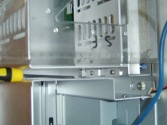
Armed with my new 300mm long magnetic wonder, dismantling the case was easy.
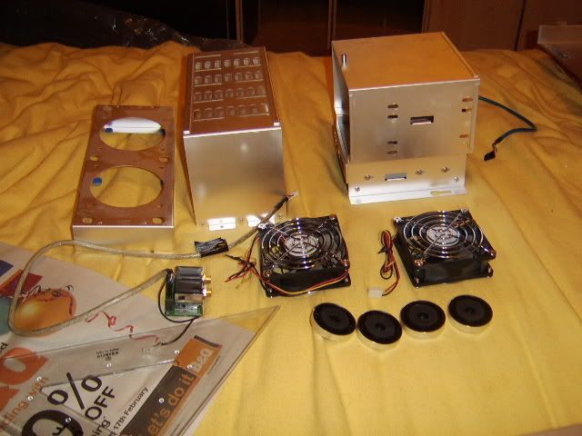
First out was the HHD rack and fan rack below that, quickly followed by the optical drive
bays and 80mm case fans. To get at the final leg fixing. the audio jacks also required removing
leaving the case quiet bare.

internals.jpg

Host of removable parts.

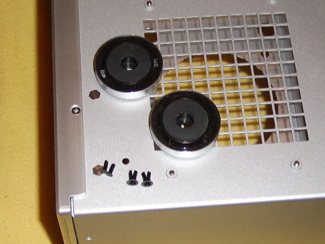
The legs were held on by a plastic push fit rivet (similar to the S775 stock cooler pins) and
could be easily removed by pushing the ‘pin’ back inside the case. This allows the ‘beak’
to close and the rivets to be pushed back inside the case.

legs.jpg

Image shows the pins (bottom left) and beaks (bottom middle) and the fixing hole between.
These together with the detached legs are resting on the underside of the upturned case.

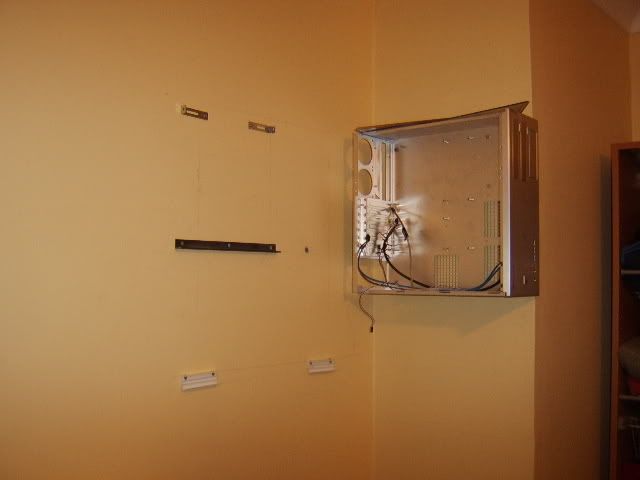
With all the legs removed, together with most of the weight I used the case as a template
to mark-up the wall. I discussed various possible heights with my wife and we decided
on 2m from the floor to the top of the case. This aligned with the top of the open wardrobe
to the right and door head high to the left.

The case was positioned with a 20mm overhand and a 60mm service zone at the rear.
This raised the problem that the original leg position at the front of the case was too close
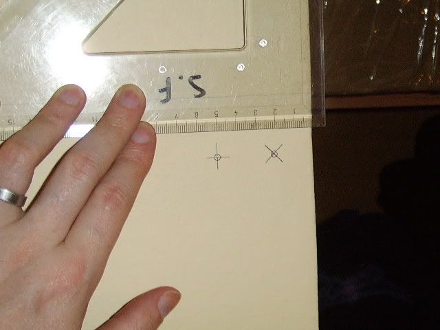
to the corner of the wall for a stable anchorage point. So I needed to make a new hole
30mm back from the existing and mount the leg

markup.jpg

Wall marked with new and original fixing locations (Left to right)

hole.jpg

Here you can see the newly drilled hole (counter sunk) just below the HHD fan grill
 
Phase 2: Cont.

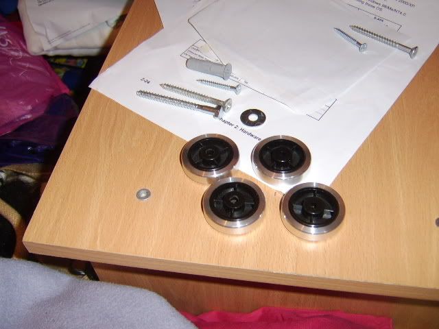
This next image shows the four legs, the left hand two having been re-drilled with a 8mm
bit to allow the new fixings. Above these are the fixing screws, I was going to use the large
machine screws (bolt ended) but at 3” they were to long. Lucky I had four spare 2.5” screws
(Philips) that were up to the job and fitted the 10mm Dia wall plugs I had available.

fixing.jpg

3” 2.5” and 1.5” screws with 10mm heavy duty plug and re-drilled legs.

After delivering my wife and son at the grandparent’s I returned home to dust off the drill
and make quiet a lot of noise.

When drilling walls I would encourage every one to use this tip. Hold drill in one hand and
dustpan in other – line up drill – hold dustpan against wall just below drill bit – drill to require
depth with all the dust captured in the dustpan. If there’s two of you works even better
with a vacuum cleaner.

Anyway swapping the drill bit for a Philips blade and bingo one wall mounted case.

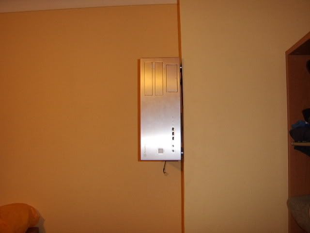
case1.jpg

Front looking all shiny and new

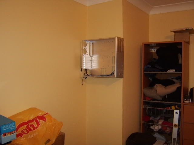
case2.jpg

Side shot – ready for instilling the pc.

Next up, wall the mountings for the Res2 and DS radiator. The Res2 wound be sitting on a
mild steel angle, fixed via three 1.5” screws and plugs. Additional at the top are two brackets
to stop it tipping away from the wall – these would be later reinforced with industrial Velcro.

brackets.jpg

Side shot – ready for instilling the pc.

The radiator had it’s own fixing strip which had self adhesive tape on the rear of the channel.
Just to make sure it didn’t remove the wallpaper and fall off I added two additional 1.5”
screws and plugs to each piece.

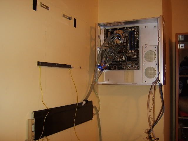
The board, loop and HHD fan caddy were added next after I realised that the Apogee was
not going to fit through a 80mm fan cut-out. With a maze 4 GPU block on route of wasn’t
about to drain and refill my system twice and as many weeks, so would live with an open
case for now and drain the loop to fit the new block and tubing correctly next weekend.

rad.jpg

Mobo, rad and loop blocks & tubing installed.
 
Phase 2: Nearly there

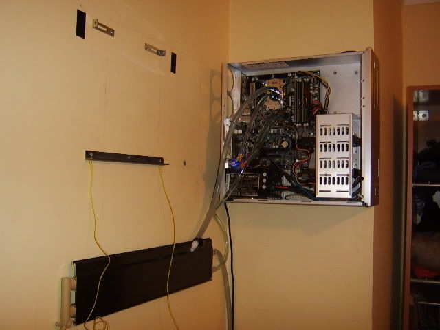
Next in was the HHD cage inc my raptor and Seagate (these will be bungeed later) and
the PSU which I couldn’t fix any of the screws into easily. I also took this opportunity to wire
up all the case leads and make things a little neater.

psu.jpg

PSU and HHD installed.

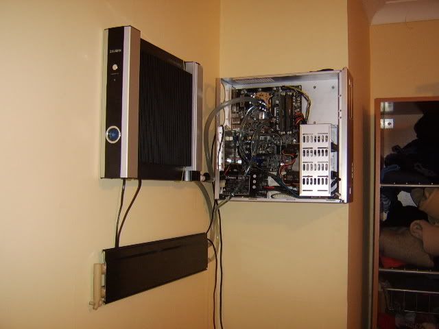
I’m getting quite excited now as I mount the Res2 and decide that using additional Velcro
and some nylon string to double fix it back to the wall. The damage that 9kgs of aluminium
and feser would do if they fell 2m is not something I want to find out first hand.

almost.jpg

Res2 now in place

semicomplete.jpg

Semi-finished result, Rad need to be slid to right to aline with Res2 above

Installing the top and bottom covers to the DS radiator and a bit more tidying and I’m feeling
quite please with the result. I next have some fun installing all the cables, switch on, power up.
All the right initial noises as HDD spin-up and coolant flow meter spins, but screen stays
in standby mode :(

Infact after hours of tinkering on the wall and on my work bench I couldn’t get the motherboard
to POST – Gutted

Tried again and gave up Sunday night, was so fed up I packed every thing back in it’s
original boxes and went to bed at 9 complete disheartened. :mad:

Works, been keeping me busy until today, but I’ve brought a b-grade Gigabyte GA-P35C-DS3R
and together with the new block I’ll get this project finished soon. :)
 
Last edited:
Phase 2: update

Board and block arrived yesterday :D

Did try one last time to get the Abit running, but hung during post again.
The new Gigabyte works a treat, with a few driver updates (chipset, LAN & Audio)
and re-validate windows, I have a working PC again!
But OMG the raptor is loud without the bungee mod and no case to enclose it!
I'm also quite impressed with the noise level of the stock cooler on low rmp - first
time I've ever used it. Ok it's not dealing with an OC at the minute but my E6600 is
at 100% load.

Should be able to upgrade the loop at weekend and with luck, a few of the other
elements as well.

Thanks for the kind works guys, it should be long until I can do the 'glamour' shots :D
 
Phase 3: Screen & Arm

After a blown plug fuse caused me to buy a new psu and much head
scratching I now have a working PC again :cool:

I need sleep but spured on but the Grrrrrrrrrrrrrate Tiger build I thought
I'd post a few images

I'm still on air cooling at present and the confinds of a case has pushed
up the fan RMPs so folding 24/7 is out the window :( but at least home
working gets me more time with the little one :D

install1.jpg

The new Gigabyte board installed

As anyone to the motherboard section of the forum knows this version of
the very popular DS3 series is prone to ram slot faults and the removed
the power lead to clear bios solution :rolleyes:

Anyway as a P35 board for less that 40inc I can forgive it's faults - I've
had it running with a FSB of 368 but it wasn't Spi stable (was only on
1.35v so not really a surprise as it doesn't overvolt like my old abit)

Better cut to the chase and flesh out the log tomorrow/wednesday when
I've more time. Here's where I'm at

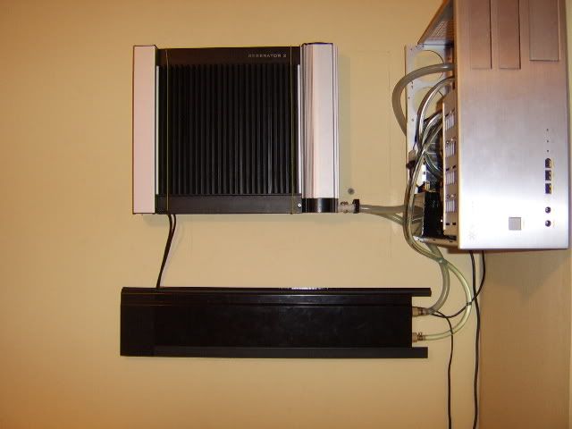
wallwork.jpg

Four of the five main parts instilled

In two minds to either cut the rad down, centre the rad or add a
shelveing strip below the case - extra storage is winning at present,
but will decide when the fifth element is installed.

All the extras to follow inc why this happened :o

tubedamage.jpg
 
Last edited:
Phase 3: Screen & Arm - Details

Back to the details of the log and my weekend.

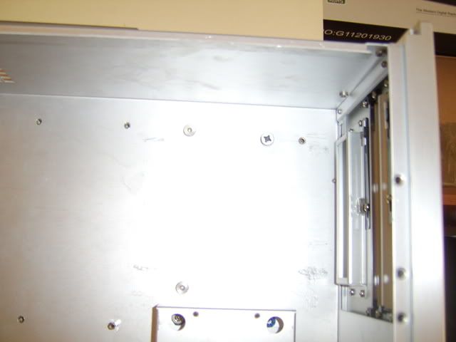
raisedscrew.jpg

Top right internal of case

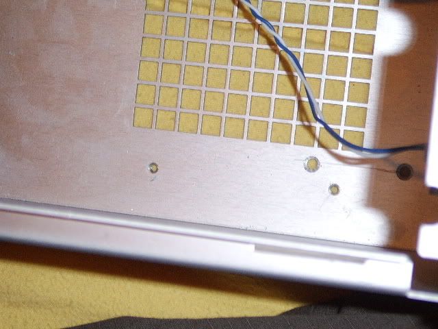
In the image you can see the (Working right to left) The original mounting hole, the new
screw fixing, the drive bay retention nut, and two of the motherboard stand off mounting
holes.

Despite counter sinking the case floor, the four wall fixing screws were still a good 2-3mm
proud. The original plastic rivets that held the feet were almost flush so the instillation of the
drive bays above were unhindered. I needed another plan.

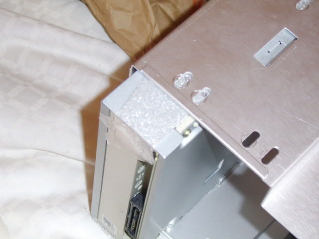
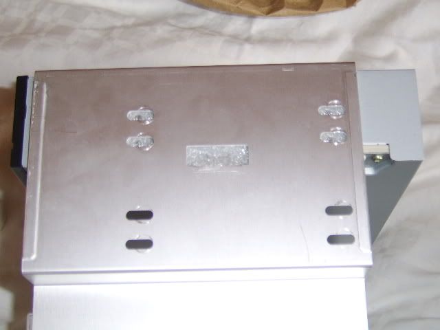
cut.jpg

Modified drive bay

Break out the hack saw and remove part of the drive bays ‘skis’ so that the head of the
screw no longer fouls the instillation. As you can see for the photo I’d already installed
the dvd-rw when I found out the problem. On that note…

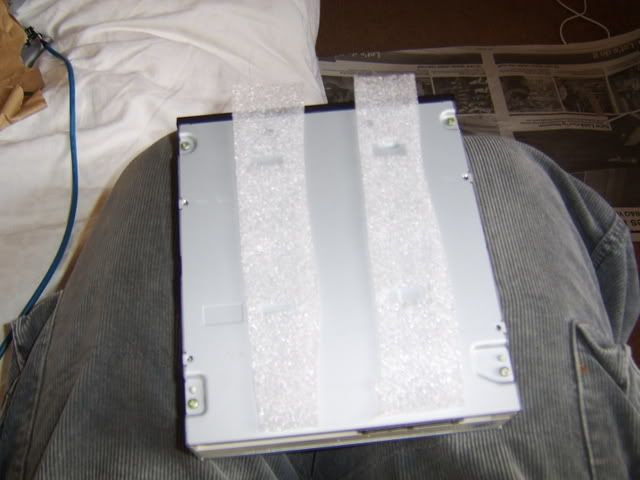
underfloorins.jpg

Cut two strips of laminate flooring insulation.

tightfit.jpg

Tape to rear of drive and carefully insert drive into bay (tight fit)

alltrimed.jpg

Remove tape (micropore again) trim up and no screws required

Will bungee mod these later but this will do for now.
 
Last edited:
Phase 3: S&A – Details cont.

spacer.jpg


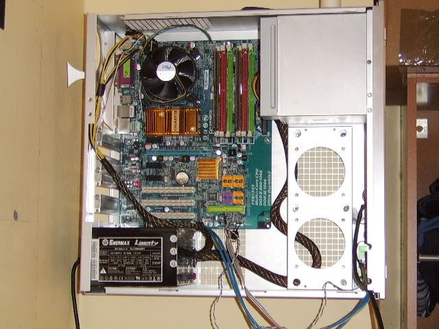
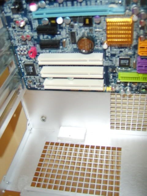
Installing the PSU was another challenge as the mounting screws on the rear were not
very accessible. It would be possible to install the psu and then mount the case on the
wall BUT only with three fixing as the psu covers the forth.

Also due to the design of the case you couldn’t just rest the psu in its designed location.
This was due to the case edge (just visible in the bottom of the photo) being folder to accept
the cover.

To stop the psu being at an angle, I used a small piece of Styrofoam as a prop or spacer.
This was high enough to snugly wedge the psu under the cases recessed pci covers (left middle)
as the case wasn’t going to be moving anywhere I was happy to leave it wedged.

You may have noticed that the case doesn’t use the psu fan to cool the case. Which suits
my purposes now I’ve using chipset and gpu blocks but this case is really designed for the
use of fans. I also should point out that the fan exhausts towards the Res2 (deliberate
to increase air flow over fins) and bypassing the case internals reduces the exhaust air temp.

I would note that by rotating the case so the side vents are now top and bottom it improves
the cooling of this case significantly. I wouldn’t take much to setup a low velocity wind
tunnel, working with the physics of hot air rather that perpendicular to it.

install1.jpg

Installed psu and Motherboard.

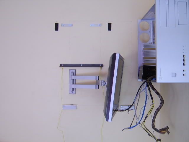
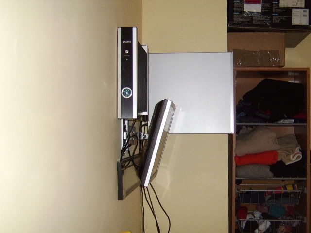
The screen and arm was one of the easier parts of the build but I’d recommend that anyone
buying one has rotation manipulation or wall brackets with slots not holes. With
the best will in the world I couldn’t get my two fixing holes perfect aligned in the soft concrete
block wall of my house. The holes were about 1-2 degrees from true and when installed
the screen is only just noticeable at an angle.
Sometimes
its worth paying double to get it perfect.

screen.jpg

Almost true and level

screenandarm.jpg

Psu visible without Styrofoam prop in place

45angle.jpg

Side shot

As you can see I installed the arm and screen as one of my first jobs (drilled wall when
my son was at grandparents) but then removed it so I could work inside the case more
easily. It can be parked well out of the way (arm extended full to the left) but I didn’t want to
scratch or damage the screen during the build.
 
Phase 3: S&A – Details cont.

Unlike most of the rest of the build I thought I’d do a bit of prep to the watercooling install.
Now most peoples watercooling set up use 10-18w pumps that have the oomph to push
the coolant round their loops. My quiet little pump is a mere 3w, and although more that
strong enough to move a filled loop – really struggles with a new install. Therefore I’ll be
priming the loop with the aid of gravity and installing the blocks / loop when filled. Firstly
due to the Res2 quick coupling splitting the loop is easy but slotting the blocks – especially
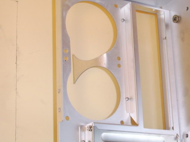
the swiftech into the case isn’t. So it’s out with the hacksaw again to join the two 80mm
fan outlets.

cutfanvents.jpg

Cut and bend

I may remove the middle section entirely (and add a grill) or may just bend the aluminium
back when the loops installed I’ll decide later. Currently I can thread all three block and
the filled loop into the case without removing it from the wall. It’s a lot of hassle I know
and I did consider installing an extra Cmag pump into the loop to increase flow rates and
oomph. But when filled the three blocks has less impact on flow rate that the two original
Zalman ones so it’s seams pointless to add extra noise.

The tubing hasn’t faired very well in storage with major kinks in a few locations. So I’ll be
redoing the loop prior to installation.
I also had great fun trying to get the system working following a blown fuse on the kettle lead
to the psu. The extension lead was ok (power and surge protection lights on) and the screen’s
led was flashing away – didn’t think to swap the cables before borrowing a friend psu.
On installing second supply – still nothing so it was then that I tested the lead – and found
the dead 5amp fuse. System loading into windows fine – swapped to my enermax and all
was fine (and a great deal quieter)
I can’t recommend quality psu enough – my liberty will probable outlast me.

And with that the logs up to date so I’ve moved one of the update images to the end
to keep things tidy and add more when I start on the watercooling in earnest

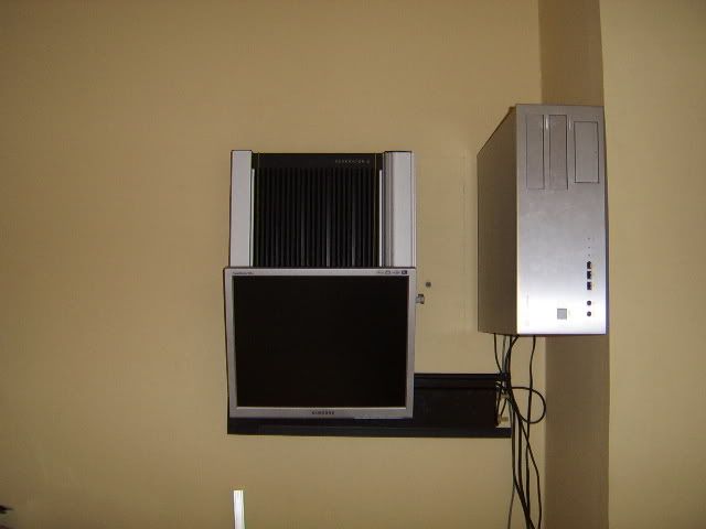
wallwork2.jpg

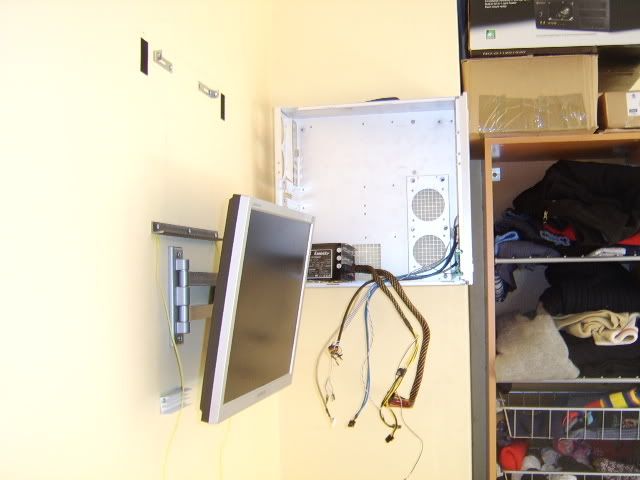
Side profile – current view as you enter room.
 
Great work. What are your plans for the monitor cables which little one may be able to grab on to?

The monitor cables are wraped round the arm and then ducted behind the DS rad. The power then drops down and the data up.

The screen is also at standing eye level so no parts are within reach (well for a few years anyway) as I've a draftman's swivel chair (seat position is about 900mm high) to use when the final part of the build in constructed. Looks a bit like this, just think of a office chair with a pneumatic cylinder twice the length.
g5931.jpg


The four cables handing down in the last shot (wireless mouse/keyboard sensor, cpu power, Res2 power and screen power) are all in the corner and will all be contained in mini trunking.

But now you've mentioned it I might use some dado trunking at the same level is the rad ...

The power leads aren't long enough to reach the floor and even if they were that still doesn't make it little finger proof
(he's old enought to know that he can't play with sockets - not that he's got access to any in our house)

Thanks Morte, you've got me thinking - Off to reserach silver dado, or even ... *sounds of gears turning*
 
Last edited:
Phase 4: Desk.

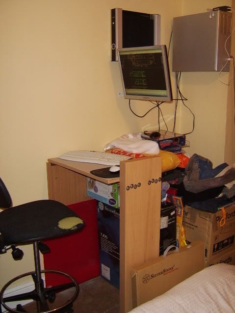
I’ve a usable workstation :D
It’s not quite as I planned and it’s still a long way from being finished but I now have a permanent
area of little finger proof work space.

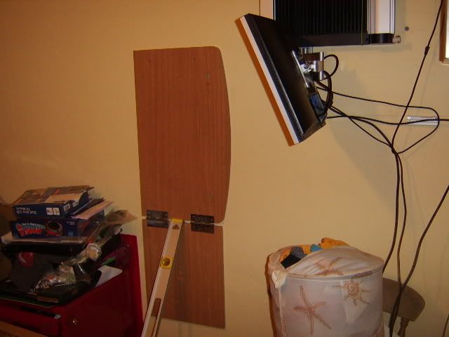
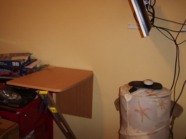
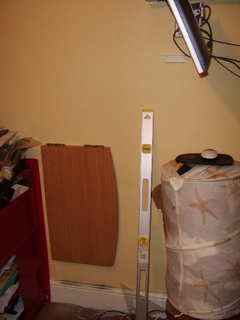
The hassle factor of converting a TV unit (in very first images) into a fold down desk were
at first straight forward – first three images and about 2h work. The mechanism of the leg and
retaining system are still not completely resolved (some 10h later)

Anyway on with the show.

desk3.jpg

Desk propped in upright position. (after wall fixing lower section - it actually stayed)

desk2.jpg

A desk. (legless)

desk1.jpg

All fixed and folded down.

Edit: first idea was for a fold out support (hinged to RSH of wall fix panel) this would fold
perpendicular to wall and then the desk would rest ontop. (forming corner of cube) But the
problem with this as that the front right corner of the desk would be very live (bouncey)
That said if I'd known the grief that a more stable, folding leg would cause I'd have gone with it.

All I wanted was a simple fold down leg. But I got side tracked with a trip to Ikea / my wife’s
aesthetic demands. Anyway the aluminum breakfast bar leg, was to short (800mm max) and
the variable alternative was chrome (not in keeping with bedroom but would do 950mm) In
the end a bracket-less shelve presented it’s self – right wood, right length, good depth (used
as width in my case)

But a thick hollow shelve has limited fixing potential – and my current solution means it will
not fold flat against the wall as yet. (End of bolts project under desk)

desk4.jpg

Workstation with ‘to-be removed’ stuff behind.

So as I come to the end of another eventful weekend I’m still along way from finished but
for the first time I’ve all the major elements in play and can work. I could
add more be this isn’t a furniture forum so I’ve kept it brief ;)
 
Last edited:
Man you are a glutten for punishment! I thought I was bad, but reading this build has just triggered so many memories of me realising I should have done so-and-so first, and now I have to spend a further 5 hours to get back to where I am!!! I have a very simple suggestion for you with regards to your desk. What I would do, is buy a chrome covered hollow metal tube, (or solid wood if you are not into metal.) Then you can buy in varying sizes from B+Q or Homebase etc, the matching diameter 'holders' (tube end sockets!)

http://www.ironmongerydirect.co.uk/...ittings/Tube~End~Sockets_10-010-19CP_574.aspx

(don't think these guys sell owt computer related!)

that fit the diameter of the pole exactly, I used one for the end of my kitchen worksurface where it goes over the washing machine. All you would need is a rubber stopper on the end attached to a 6" square thin base of wood etc, then when you want to take the desk down, simply lift it up slightly, and remove the leg, store in a corner out the way. Loads more simple solution than having to think up a mad folding mechanism. Just a simple idea, maybe it'll save some of your hair :D

Good luck with the build mate, coming along very nicely indeed.
 
Last edited:
I did look at that option, but the 'shower rail' type polls, even with two of them would be
unstable if my son decided to swing/shake/run into them. (resulting in the deck smacking
him in the head as it folds shut :eek: so not really an option)

I really appreciate your comments and suggestions though - and you should see the precautions
I take when using power tools within the house. Talk about adding extra work for myself!
- but the alternative is not worth thinking about with a button loving 2 year old

To be honest, I knew that the build wouldn't go smoothly, but that's a good thing to share
sometimes. Most logs are started by people 100x more skilled that me with really high
end kit - and there're really inspiring (tiger, android, bioshock etc) but I hope that my up's
and downs also motivate the lesser skilled to try a simple bungee mod for example or even
fix that old shelf ;)
 
Last edited:
Quick update.

I've managed to get 8x countersunk, M6 60mm bolts so the desk will be sorted and fixed
in it's upright position tonight - photo's to follow

Oh the joy of having a proper hardware store near work. - with over 200 different
nuts/bolts/screws available individually or boxed per 50/100/200 and someone
that actually knows their stock available to ask!
 
Last edited:
Back
Top Bottom