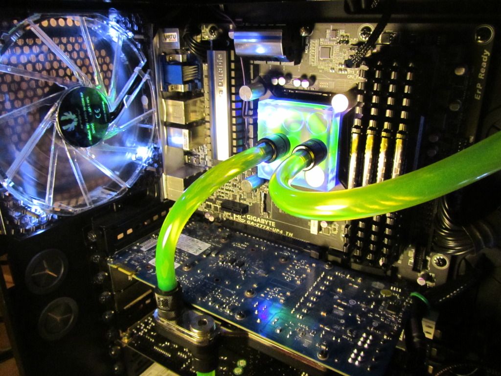
650D Watercooling Project

Associate
OP
Joined
27 Nov 2006
Posts
1,329
Location
Coventry
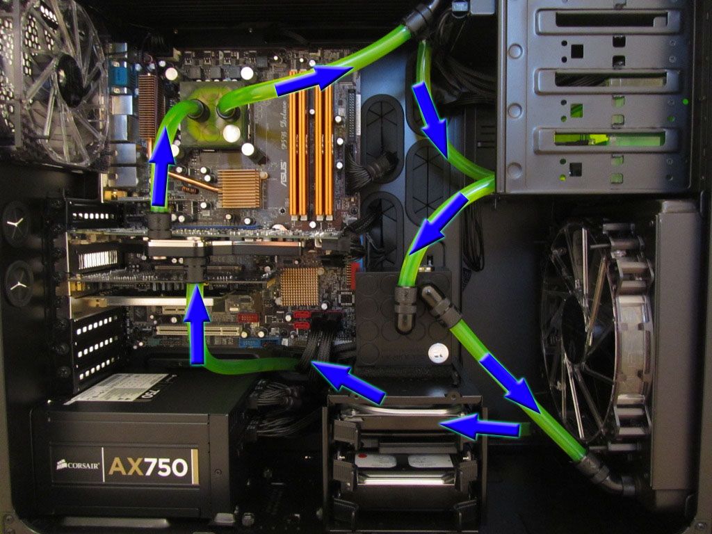
A little diagram to help you.

But the reservoir will always feed down into the pump. Probably the easiest way of working it out. Or look at the pump in and out. On the D5 pump I have there, the inlet is always the middle port. You can work it out from there

FlowPath.jpg


Hope that helps!
 
Last edited:

Deleted member 651465

D

Deleted member 651465

That's good to know. This is what I had worked out, but was unsure because the graphics card feeds the cpu :)

I have the same pump and I have basically used the same wiring except I have a tube res, so I've had to move the pump to the right of the drive cage.
 
Man of Honour
Joined
8 Nov 2007
Posts
16,034
Location
Outer Space
@ OP, lovely job man :D

I'm also starting on my first WC'd build, so its interesting to see what you've done. Can you link me (on OCUK, or make and part number if not) the bits needed to do the drain port please, something I've not looked into yet?

Thanks :)
 
Associate
Joined
15 Jul 2012
Posts
1,940
Looks great! Didn't like the idea of green but the contrast is nice and looks great on the front. Makes the 650D look so much better than it does with all those empty drive bays.
 
Associate
Joined
19 Aug 2012
Posts
1
I like your drain port.

Can you be more specific as to how you did it? (like think the 3 products you used)..

Im about to do an almost similar setup with the same case, its looks awesome!! Good job!
 
Associate
OP
Joined
27 Nov 2006
Posts
1,329
Location
Coventry
Thanks for all the nice comments guys :) Appreciate it.

Also, can I ask what did you use to spray the DVD RW drive black, the old beige ones look awful :(

It was just some matt black bodyline spray paint/primer I believe. Just some I had spare from painting my car.

As for the drain port chaps, I will have a look at the exact items tommorrow hopefully, and get back to you. Quickly from memory though, it was a T-piece, screwed into a bulkhead pass-through fitting, and a blanking plug to seal it up. Hardest bit was drilling a hole in my lovely new case!
 

Deleted member 651465

D

Deleted member 651465

I'd like to add my 2p, regarding mounting the 200mm rad without mods.. I figured this out on the weekend, while trying to copy your mounting method, but adapt it to a push setup.

If you get the rubber fan mounts (I have Akasa ones with 2 knobbly bits), you can actually mount the rad without any form of mod. You don't even have to chop the rubber screws :)

  1. Put the rubber screw through the mounting plate (facing front). I used an M4 washer just to ensure the rubber screw doesn't go anywhere.
  2. Screw mounting plate to the rad.
  3. Slip fan over rubber screws until the second knobbly bit passes the fan itself
  4. Position the rad and fan in the case and align the rubber screws with the fan mounting holes in the 650D.
  5. Push the rubber screws through the mounting holes of the case until the second knobbily bit passes the rubber grommet of the case.
  6. Slip M4 washers over the protruding rubber screw and over the second knobbily bit.

You now have a push setup, that requires no modding and can be easily removed. The benefit is, because the rubber screws are stretched past the fan and case, it's solid as a rock.
 
Last edited by a moderator:
Soldato
Joined
5 Nov 2006
Posts
3,133
i
I'd like to add my 2p, regarding mounting the 200mm rad without mods.. I figured this out on the weekend, while trying to copy your mounting method, but adapt it to a push setup.

If you get the rubber fan mounts (I have Akasa ones with 2 knobbly bits), you can actually mount the rad without any form of mod. You don't even have to chop the rubber screws :)

  1. Put the rubber screw through the mounting plate (facing front). I used an M4 washer just to ensure the rubber screw doesn't go anywhere.
  2. Screw mounting plate to the rad.
  3. Slip fan over rubber screws until the second knobbly bit passes the fan itself
  4. Position the rad and fan in the case and align the rubber screws with the fan mounting holes in the 650D.
  5. Push the rubber screws through the mounting holes of the case until the second knobbily bit passes the rubber grommet of the case.
  6. Slip M4 washers over the protruding rubber screw and over the second knobbily bit.

You now have a push setup, that requires no modding and can be easily removed. The benefit is, because the rubber screws are stretched past the fan and case, it's solid as a rock.

Nice one - will have to take note of this for when I do this for my 650D.

Mark
 
Associate
OP
Joined
27 Nov 2006
Posts
1,329
Location
Coventry
Glad to see my guide has helped you. I decided on pull to eliminate the horrible fan noise the 650D makes when the 200mm fan is next to the front vent. I didn't want to cut it out, like many have done.
 
Associate
OP
Joined
27 Nov 2006
Posts
1,329
Location
Coventry
Managed to get some time away from work. Hopefully I can tell you a bit more about this fill port. It's all quite simple.

The location: The drain port must be at the lowest point in your loop, else it simply wont drain fully.

The bits needed:
-OcUK Fillport Black Nickel - Knurled - Universal [45247]
http://www.overclockers.co.uk/showproduct.php?prodid=WC-075-OE&groupid=962&catid=1529&subcat=2059
-OcUK G1/4 - Screw in Seal Cap - Knurled - Shiny Silver
http://www.overclockers.co.uk/showproduct.php?prodid=WC-076-OE&groupid=962&catid=1529&subcat=2059

-1/4" Thread Rotary T Piece for 3/8" ID - 1/2" OD (10-13mm) Tubing : Black Nickel
(Not from OcUK)

Unfortunately OcUK don't stock any T-pieces, so I had to go elsewhere for that. But do a google I'm sure you can find one easily...

The setup:
-You will need a hole, obviously, in the bottom of your case. I drilled out an existing hole, large enough to fit the "Fillport" fitting through.
-The T-Piece has 2 compression fittings at the top, plus a standard G1/4 thread at the bottom. Your loop is plumbed into the two compression fittings (bear in mind to get the right size T-piece for the tube, mine was 3/8").
-The bottom of the T-piece is then screwed into the fill port we fitted in the first step.
-Now all is left it to screw the "Seal Cap" into the bottom side of the bulkhead filling port.

9pnntg.jpg


Let me know if you need any more help or don't understand!
 
Last edited:
Associate
Joined
1 Jan 2012
Posts
1,945
Location
Scottish Borders - UK
Managed to get some time away from work. Hopefully I can tell you a bit more about this fill port. It's all quite simple.

The location: The drain port must be at the lowest point in your loop, else it simply wont drain fully.

The bits needed:
-OcUK Fillport Black Nickel - Knurled - Universal [45247]
http://www.overclockers.co.uk/showproduct.php?prodid=WC-075-OE&groupid=962&catid=1529&subcat=2059
-OcUK G1/4 - Screw in Seal Cap - Knurled - Shiny Silver
http://www.overclockers.co.uk/showproduct.php?prodid=WC-076-OE&groupid=962&catid=1529&subcat=2059

-1/4" Thread Rotary T Piece for 3/8" ID - 1/2" OD (10-13mm) Tubing : Black Nickel
(Not from OcUK)

Unfortunately OcUK don't stock any T-pieces, so I had to go elsewhere for that. But do a google I'm sure you can find one easily...

The setup:
-You will need a hole, obviously, in the bottom of your case. I drilled out an existing hole, large enough to fit the "Fillport" fitting through.
-The T-Piece has 2 compression fittings at the top, plus a standard G1/4 thread at the bottom. Your loop is plumbed into the two compression fittings (bear in mind to get the right size T-piece for the tube, mine was 3/8").
-The bottom of the T-piece is then screwed into the fill port we fitted in the first step.
-Now all is left it to screw the "Seal Cap" into the bottom side of the bulkhead filling port.

9pnntg.jpg


Let me know if you need any more help or don't understand!


some nice info there mate!
 
Associate
OP
Joined
27 Nov 2006
Posts
1,329
Location
Coventry
You're welcome chaps.

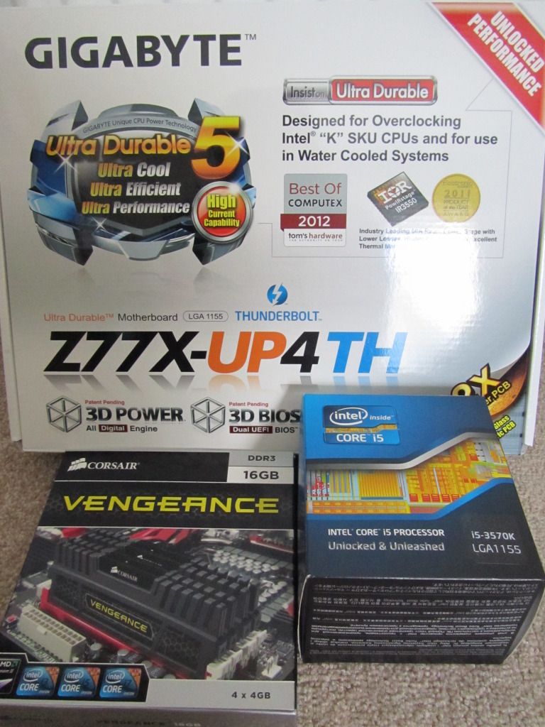
Quick update. Got a new motherboard, CPU and RAM this week. Took a couple of quick photos, not great quality, but don't have much time :p Its a Gigabyte UP4, i5 3570K with 16Gb of Corsair Vengeance. Colours match far better now!!
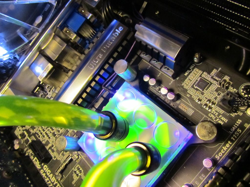
IMG_1719.jpg


IMG_1740.jpg


IMG_1737.jpg
 
Last edited:
Associate
OP
Joined
27 Nov 2006
Posts
1,329
Location
Coventry
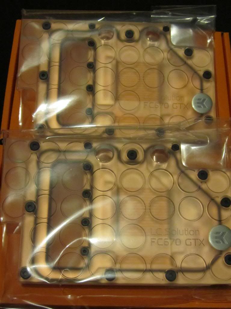
Well, 9 months since I last did an upgrade. I got the itch and decided to get myself a pair of GTX 670's.

My pair of water blocks for them arrived today!

IMG_2485.jpg


I ordered the black acetal version, as this was the only variant OCUK had 2 of in stock... But have obviously received two of the plexi versions instead :confused:
I'm not complaining as the plexi costs £5 more each... But does mean I have had to return the bridge I bought, at my expense, as it now doesn't match. And wouldn't you know the plexi bridge is more expensive too! Grr.

On a side note, why does OCUK insist on using a box over 2 foot long and 1 foot wide to ship a couple of water blocks and a bottle of fluid? Surely you guys have smaller boxes :rolleyes:
 
Back
Top Bottom