Anglia Project

Soldato
Joined
18 Oct 2002
Posts
8,016
I blame my dad entirely for my passion for cars. He's a mechanic by trade, but he also enjoys tinkering with cars in his free time.

So, I grew up surrounded by cars, and from an early age I wanted to spend all of my time with him, watching what he was doing, learning, and just generally getting under his feet and in his way. Fast forward to today, and I'm much the same, albeit now I've got a bit more knowledge, and am now a bit too tall to literally get "under his feet" (but I sometimes still do in the figurative way).

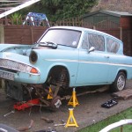
In the mid 90's, my dad got his 2nd Ford Anglia - a 1966 Deluxe, which was in quite a sad state, and needed a bit of repair work. Unfortunately time was tight, so it was completed, with a 1500GT engine (later a 1300 crossflow) and it went on the road. I loved going out in the car, it turned heads everywhere. A few years later, he picked up another, in worse condition! This one took longer to restore, but having done something with "period" mods, this one went extreme - he took the largest shoehorn he could find, and squeezed in the full running gear from a Subaru estate car - 1800cc flat four engine and full 4WD running gear.


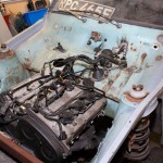
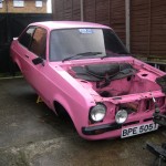
In 2003 I managed to get hold of a 1967 Ford Anglia Deluxe, which had failed it's MOT on a few items and the current owner couldn't afford the repairs. I started off by getting myself a Mk2 Escort with a 1600 crossflow, with plans of putting that in. I made a start, but didn't get much further than stripping the car to mostly a bare shell with the Escort front suspension fitted, before other events took over and it got sidetracked.

I then changed my daily driver to a Honda Prelude 2.2 VTEC, and decided that my "fun" weekend car shouldn't be slower than my daily driver, so got hold of a Nissan 200SX S13, with a 1800 turbo engine.
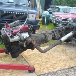


I stripped this down, but before I could make a start, I ended up damaging my Prelude, so spent a few months rebuilding that! The Anglia took a back seat again. Unfortunately, it continued to take a back seat until October 2010, when I started again on it.

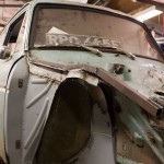
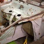
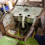
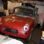
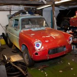
The years sat outside at my dad's place had taken their toll on the car, which had developed much more rust, and it required quite a bit more work than it would have done 6 years earlier...
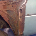
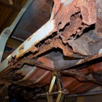

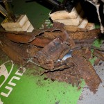
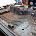
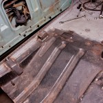
So we removed the rust, and using replacement body parts from the Owner's Club, repaired these areas and put strength back into the car.

Removing rust...

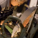
Fitting new bits...

Nice new, strong metal...
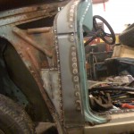

Once the strength was put into the chassis, it was time to start thinking about fitting the running gear.

However, I'd since (again) changed my daily driver to a Mitsubishi Legnum VR-4, and the 1.8 turbo engine again would have been less powerful than my daily driver! So... I've changed the choice of engine (again)!


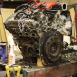
So, introducing the Mitsubishi 6A13TT engine, as is in my Legnum VR-4:
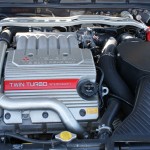


2500cc, V6, 24 valve, quad cam, twin turbo, 280bhp.

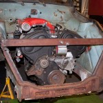
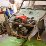
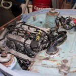
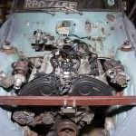
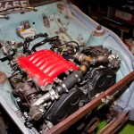
With an engine from an old Galant (the saloon version of my Legnum estate), I decided to see whether it would fit in the engine bay of the Anglia.
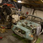

Lifting it towards the unsuspecting car
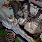

With the turbos still attached... not quite, how about without the turbos?
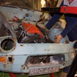

Much better!!

The 6A13 engine was never used in a Rear Wheel Drive vehicle by Mitsubishi, therefore, there are no gearboxes available “off the shelf” that will allow it to be used longitudinally.

The 6A13 is, however, compatible with gearboxes that also bolt up to the Lancer Evolution IV onwards 4G63T – but, the same problem comes – it comes in no vehicles where it’s used in a RWD configuration...

So… to the drawing board we go to find a gearbox.

Well, from my previous running gear selection, I just so happen to have a FS5W71C gearbox from the Nissan 200SX sitting around… it’s fairly compact, and the bellhousing looks a similar size to the bolt pattern for the 6A13 engine.

We had to design and have made some adapter plates to be able to attach the two together, so we began to make some templates.
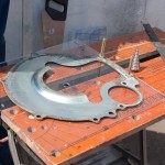
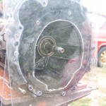
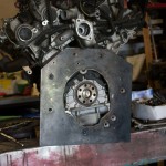
I picked up an FTO flywheel, which is the same 225mm as the Nissan gearbox (the engine came from an automatic), but with the 8mm adapter plate we had made by a local engineering firm, the back edge of the flywheel was a bit too close for comfort, so we had made up a 5mm spacer to bring the flywheel away from the block.

In a RWD box, the input shaft is supported in the end of the crank, but in a FWD or transverse gearbox (as in the VR-4) has the input shaft supported both ends within the gearbox itself, so there are no spigot bushes, and therefore no way to mount one into the VR-4 engine. So, again to our local engineering firm, who turned us up a spigot adapter to fit the end of the crank, and to fit the brass spigot bush from the 200SX.

With these adapter plates made up, and a combination of Mitsubishi FTO flywheel and clutch and the Nissan clutch, and a home-brew release bearing using FTO/200SX bits, we have managed to mate up the Mitsubishi 6A13TT engine to the Nissan 200SX FS5W71C gearbox!
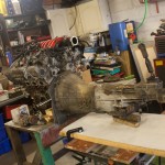
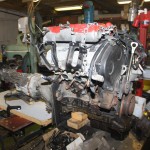


We then began to fit the gearbox into the car, making up a custom gearbox cross-member, and minor modifications to move the location of the gear lever.
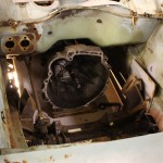
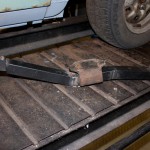
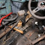

We were then able to drop the engine in place, mate it up to the gearbox again, and even fit the Nissan propshaft - which was the perfect length to mate up to the standard Anglia rear axle!!
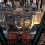
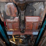


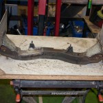
So, here we are, with engine/gearbox/propshaft bolted together - next on the list is to modify the front crossmember to remove the existing engine mounts, as we'll be making up new custom engine mounts.
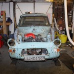
 
Last edited:
Soldato
OP
Joined
18 Oct 2002
Posts
8,016
I purchased the Mk2 Escort complete for £170. I sold just the shell via eBay for £175, so I certainly didn't scrap the shell - maybe it's still out there somewhere?

I'll be keeping the turbos, but I'll probably have to make custom manifolds to relocate them elsewhere!
 
Soldato
OP
Joined
18 Oct 2002
Posts
8,016
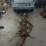
I love those "piles on the floor" pictures - it makes you realise just how much rotten stuff there was there, that was actually also still holding the car together and in the right shape!
 
Soldato
OP
Joined
18 Oct 2002
Posts
8,016
I left you last time with a marriage of an engine and a gearbox mated together - which even I wasn't sure would have worked until we managed it!

The next issue to tackle was that of actually starting the car. Our adapter plates were taken back to our local engineer with some more rough scribbles, and they were returned with some new holes.


A minor tweak, and the starter bolted up to the engine, and in line with the flywheel - and then, for the moment of truth... would it work?


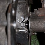
Success! Next, to get the starter fitted to the gearbox. A small bit of cutting later...


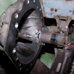
As you can hopefully see, the starter is rather close to the crossmember - and the gearbox is currently lifted higher than it will usually sit - which means that the starter will be trying to sit in the crossmember, so some modifications are required.

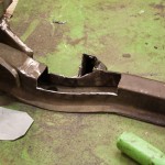
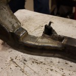
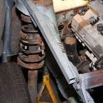
So, we cut away a section, and reinforced where we'd removed, as well as reinforcing where we'd cut away the original engine mounts, as we'd not be needing them.


The eagle-eyed among you may have noticed a couple of blocks of wood between the front crossmember and the sump of the engine in the final picture of my last update - this is what was supporting the engine in the right position. I don't think that would have been a long-term solution, so a proper engine mount is required.

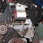
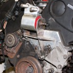
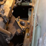
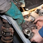
Upon my browsing of forums as I usually do of an evening, I happened upon someone selling a brand new engine mount from a Honda Integra DC2 - which looked like it might fit the bill. I promptly purchased it, and work began on making it fit. A large chunk of the original engine mount was removed, and a wonderful looking mounting bracket was created.


In order to support this, we'd need some quite hefty bracing, so the remainder of the bodywork was removed, and some additional box section was grafted into place.


The engine was then lifted back into position, and the front engine mount was affixed securely to a beefy bit of box section, and the engine suspended from it, and the gearbox crossmember.


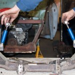
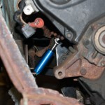
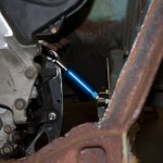
With the front and rear mounts sorted, something was needed to stop the roll of the engine. Using the mount from the Honda Integra gave me another idea. I often see Hondas with "engine torque dampers" to reduce the engine movement from their huge torque outputs *s******* - these are small units which don't take up much room... perfect for this case.

So, a couple were purchased, and mounts made to prevent the roll on the engine.


There we are - that should damp more torque than the 2 Hondas they were no doubt previously destined for!


And finally - another treat, a video which is "out of order" of the text above, but I couldn't leave this update without putting it in!

 
Last edited:
Soldato
OP
Joined
18 Oct 2002
Posts
8,016
The torque dampers are actually just glorified rubber mounts. I too thought originally that they may be some kind of fluid damper.

The piston inside has a circular disc on the end, and either side of that is a thick rubber disc, of similar type of rubber to that of a standard engine mount.

I'll have to pop the starter motor back on now it's fully supported and get another video to show the movement on the engine, and then can compare it to the previous video when it was supported just front and back.
 
Soldato
OP
Joined
18 Oct 2002
Posts
8,016
I thought it about time some control was brought to this project!

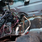
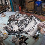
So, first off, how about some engine control, with the beginning of some of the multitude of wiring? I'm stripping out wiring for any systems that were present on the Galant, and won't be on the Anglia.

So, that means removing: ABS, ASC, AYC, SRS, TCL and Automatic Gearbox ECU.

After starting with the engine and ECU looms, and re-routing, we're currently set up as such:


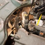
Before going too much further with the wiring under the dash, a small amount of adjustment is required to fit the water manifold to the back of the engine. Firstly we had to trim down the top of the gearbox casing.


And in order to run the coolant hoses to the front, a small amount from the bulkhead.


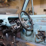
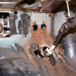
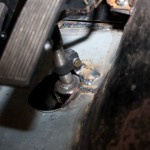
Next on the agenda is some way of telling the car where to go, so... one Mitsubishi steering column and wheel :)


With the ability to steer, I think the ability to move and stop might be the next logical step.

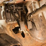
Before:


After:


The clutch/brake pedals are an old set of dual controls which were removed from another car, and the accelerator is from the 200SX.

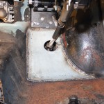
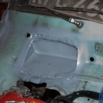
Now that the steering and pedals are done, the bit of floor that had been hacked about to previously fit the Escort steering column was then replaced with a nice fresh bit of steel.

 
Last edited:
Soldato
OP
Joined
18 Oct 2002
Posts
8,016
Yeah pretty much all the new stuff we're putting in is Zintec :)

Those He-Man pedals are nicely built, and they're very adjustable, which is great because of the limited space for traditional master cylinders and locations.
 
Soldato
OP
Joined
18 Oct 2002
Posts
8,016
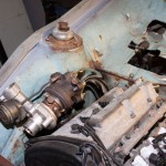
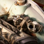
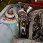
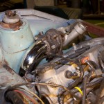
The biggest issue we've been worrying about is how we're going to fit the turbos. They won't fit in their standard locations. We decided to bite the bullet, and try to come up with a solution.

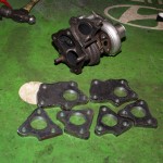
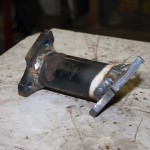
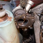
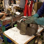
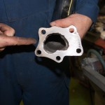
We took a trip to our local engineering firm again with a rear turbo, and a sheet of steel, and came back with a set of flanges:


One of the flanges bolted to the rear manifold:


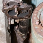
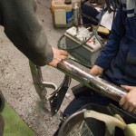
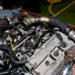
A small bit of nice thick pipe (Mitsubishi L200 rear bumper bar):


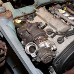
And one turbo in place:


Now to rinse and repeat for the other side:


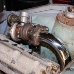
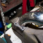
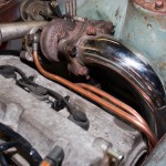
Next step is the downpipes, so out with a nice bit of stainless steel rear bumper bar, marked out, cut and welded into place:


Once we'd marked up where the downpipe would fit, we extended the hole in the flange to incorporate the wastegate before welding it all together.


Well... that wasn't as bad as we expected - only a day to mount two turbos and one exhaust downpipe. So, yes, we have blown it now! ;)
 
Last edited:
Soldato
OP
Joined
18 Oct 2002
Posts
8,016
Yeah from the outside it'll look pretty normal. Just a flashy paint job, and some 13" RS alloys.

The engine outputs ~260bhp in the original car, so it should be around that, but it'll only weigh around a ton, and be RWD rather than 4WD as in the original car.
 
Soldato
OP
Joined
18 Oct 2002
Posts
8,016
Hi Jonny,

If you look at this picture:


You should be able to see a bit of box section coming up on the angle, just in front of the turbo (in the picture), and is welded to the front panel, and the inner wing. This is also tied in to the chassis rail, and the extra thick bit of steel that is also welded to the end of that bit of open-ended box that you pointed out in the picture you quoted.
 
Last edited:
Soldato
OP
Joined
18 Oct 2002
Posts
8,016
And yes, that is some kind of old-school (and dangerous) lowering. They were on the Escort when I got it. It'll no doubt have a full set of adjustable suspension on it in the end, so they'll go!
 
Soldato
OP
Joined
18 Oct 2002
Posts
8,016
With one downpipe completed, it's time to move the turbo back to the other side, and make another.

So, one flange marked and hole enlarged to suit and welded together:


And fitted in place:


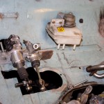
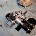
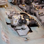
Once that was done, we moved efforts onto the brake/clutch, which we'd started a couple of days ago. We had sitting around brake and clutch master cylinders from a Honda Prelude, so began trying to make them fit. However, the brake master cylinder was too big, and we couldn't get a smooth enough action.

We had to take a trip to the scrapyard to get rid of some old junk, so we did our "Scrapheap Challenge" bit and looked around, and came back with a brake master cylinder from a 2001 Fiat Punto, which wasn't as long, and, we made up a bracket to hold them in place. Also from the Punto came the reservoir, which is shared between brake and clutch - which means less things to fit into the engine bay on the Anglia!

 
Last edited:
Soldato
OP
Joined
18 Oct 2002
Posts
8,016
This will be the final update from the week of work on the Anglia, so we finished the week by finishing up a couple of bits that had been partly started.

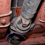
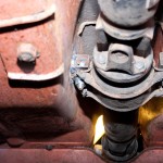
First off, the propshaft. The Nissan propshaft was the perfect length to mate up the gearbox and the standard Anglia rear axle, but it wasn't supported at it's centre joint, well, other than by a small piece of electrical wire!


A more permanent solution was required, so a couple of small bits of box section, with a bolt welded in place, and then welded to the inside of the transmission tunnel should do the trick:


Moving into the car, and the steering shaft needed supporting between two of the joints. A simple bracket, and that was done:


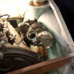
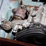
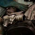
I also managed to pick up another rear turbo and manifold, as well as a manual throttle body, which doesn't have the Traction Control stuff on the side of it. We bolted the turbos into place, and we could now see how the space was being used up quite quickly!


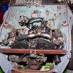
During the making of the pipework for the turbos, we decided to drag the fibreglass flip front out, and put it on the car, to ensure we'd have the required clearance under the bonnet for the myriad of pipework that will be required. So, here's a couple of photos of it looking somewhat more like a normal Ford Anglia.


Unfortunately the current schedule of visits every 4 weeks means that the next scheduled visit falls on the weekend Christmas, so no work will get done then! So, you'll have to tune in at the end of January for the next instalment!
 
Last edited:
Soldato
OP
Joined
18 Oct 2002
Posts
8,016
Continuing the tradition of "do something when we think about it", the next thing we decided to tackle was the seats.

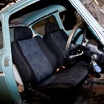
Going to the magical store room of bits that my dad has acquired over the years, we managed to find a pair of seats that were originally in a Mitsubishi Lancer Evolution VI, that were removed by Ralliart when they fitted the Recaro seats prior to selling them through the UK dealer networks.

So, we measured up, marked, measured up again, cut, put in place, and bolted/welded some supports to the floor, which will both reinforce where the seats will sit, and also allow the seat to be both level, square, and moveable.


This then allowed the seats to be put in place, and bolted down securely.


Attention next moved to the engine again, and the eternal question that we've been asking since deciding to use this engine... how are we going to actually plumb in all of the inlet pipework!?

I've been wanting to put an intercooler at the front of the car, not only does it look cool, but it will keep the inlet temperatures down. Which would mean combining the output from the two turbos, installing the intercooler, piping to and from it, and then round to the inlet on the back of the engine. Not to mention, that the pipework from the filter to the turbos also has to be put in place!

However, putting my sensible hat on, this is not going to be a track car, this is not going to be used at full power for prolonged periods (there's nowhere other than a track where I could potentially even use it for those purposes!) - so a decision was made to do away with the intercooler.

This made the decision on the pipework much simper - it wouldn't need to come down to the front of the car, so that space can be free up for pre-turbo pipework, and more essential stuff like a coolant radiator and fans!

To that end, we got to work.

First off was to turn the compressor side of the driver's side turbo round, and making up a bracket to hold the wastegate actuator in the correct place.


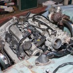
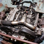
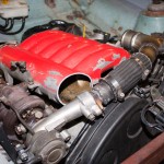
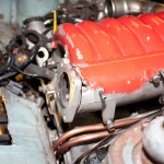
From the original VR4, I had the Y pipe that usually runs across the top of the engine, and I also acquired another. These got chopped up for bits, and a new Y pipe was made, bringing the outlet from both turbos to the centre of the engine, to head to the back, ready to loop round and into the throttle body.

As they say, a picture is worth a thousand words...


A couple of brackets will need to be removed from the intake plenum so that it will sit down flush, but that'll be a task for next time.

 
Last edited:
Soldato
OP
Joined
18 Oct 2002
Posts
8,016
Although it's hardly happened so far, which I for one am exceptionally surprised about, something that we've done hasn't been quite right, and could be improved upon.

This something was the brake & clutch master cylinders.

The place we'd positioned them previously meant that the movement on the arms from the pedals wasn't entirely smooth, and there was little space between them and the throttle body, so getting some kind of pipework onto the throttle body would have proved very difficult.

Therefore, it was decided to move them, and do our most major bit of bodywork refabrication to date.

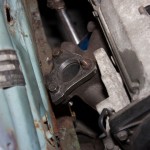
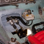
A section of the bulkhead was cut out, and a new bit welded in which will allow the master cylinders to be recessed slightly, and further back.


This brought the arms from the pedals to a more upright position, and is acting more directly on the pistons within the cylinders. It also gives more clearance between the throttle body and the pedal arms, which was then improved further, by a few modifications to the inlet plenum.


Due to the reorientation of the turbo and the inlet pipework, the plenum required a few brackets removing, and an end chopped off, so that it will sit fully down onto the engine. A small amount was taken from the end where the throttle body is, to angle the throttle body upwards slightly, again giving more clearance for the intake pipework to fit.

The plenum will be taken to be welded up fully soon.

Some water pipes were also made up on both sides of the engine for cooling of the turbos.

 
Last edited:
Soldato
OP
Joined
18 Oct 2002
Posts
8,016
Ricochet... there are no bits of paper, no calculations, no flow rates etc.

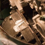
There's a couple of measurements written in permanent marker on the body of the car, I think the most important one at the moment is for the maximum physical dimensions for a coolant radiator...

As I am only at my dad's one in every 4 weekends, both myself and my dad have lots of time to sit and ponder things, and we're often on the phone to each other 2-3 times per week saying to each other "what if we were to do this", "would that work", "how about [insert idea here]". However, a lot of it is just holding a piece up and saying to each other "so, how the **** are we going to make that fit" and then do something.

So far, we've been exceptionally lucky in that many things have just fallen together - for example when marking out the gearbox/engine adapter plates, it meant that the gearbox ended up at a slight angle. However, this then worked out perfectly and meant the minimum further modifications in order to fit the water manifold to the back of the engine. However, if we'd made more precise measurements and diagrams, we'd have ensured that the gearbox didn't have that slight angle to it, and then we'd have had major issues making the water manifold fit, because it would want to right where a couple of bolt holes are!

So... we do think about it a lot, but not to the extent of diagrams and calculations!


(Actually, I've put more calculations and measurements into my current "week day" desk project!!)
 
Last edited:
Soldato
OP
Joined
18 Oct 2002
Posts
8,016
Yes, there's a lot of intake pipework still to go! I'm hoping someone will soon change the standard ECU to work on a MAP sensor, rather than the standard MAF, as that will massively simplify the pre-turbo stuff! With the MAF I'll need to find somewhere to for the MAF itself and the pipe from it to each turbo.

There is indeed a Prelude clock sitting in the car, whether we'll use it or not I'm not sure, but it looks good in photos!

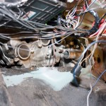
There's still some minor tweaking to do to the engine bay with a very large hammer when the engine is next out to improve clearance.

I may have space on the passenger side of the bulkhead for a header tank, it's where the original washer bottle is positioned.
 
Back
Top Bottom