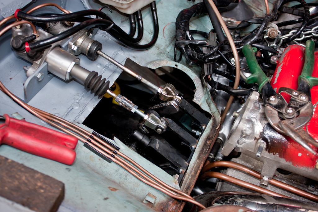
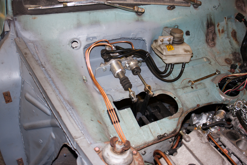
We've come to a point where the engine and gearbox being in the car is preventing us from moving on.
There's minor tweaks that need to take place to the inner wings with a large hammer, there's more pipework for the turbos to be made, and stuff like brake/clutch lines to be made up, and all of this stuff will be much easier with the engine and gearbox not in the way.
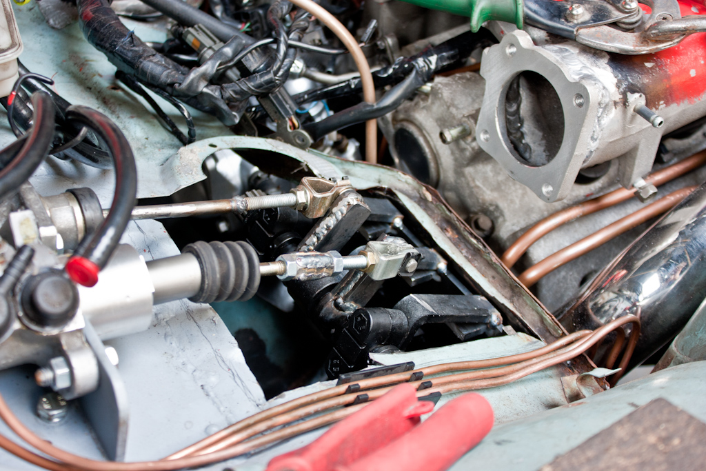
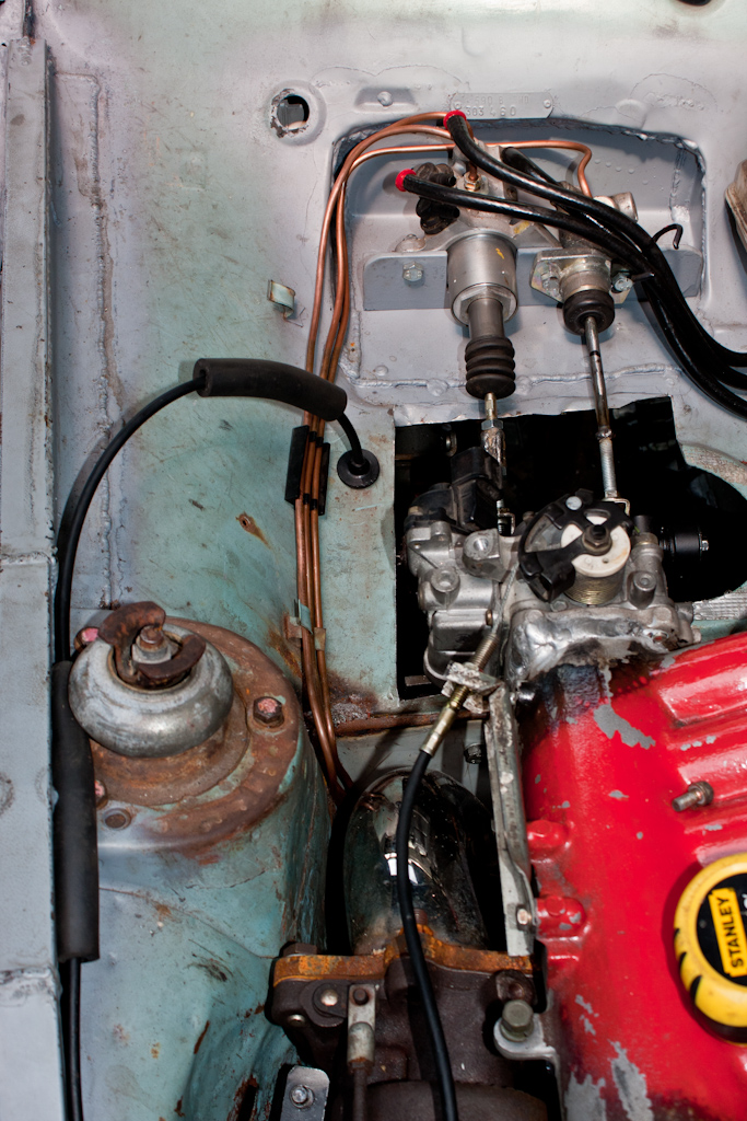
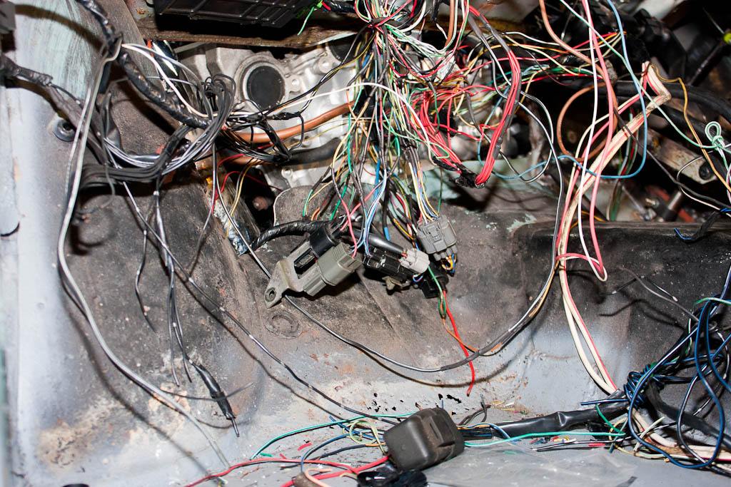
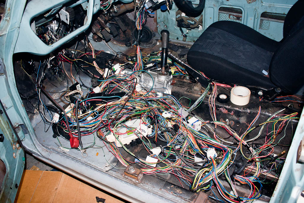
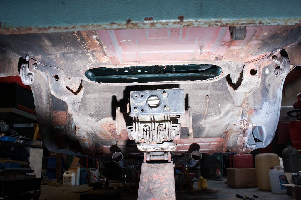
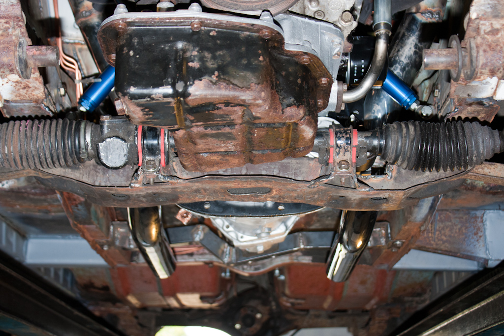
We disconnected the wiring from the engine, dropped the front crossmember down to allow us room to move the engine, and decided to see whether we could remove both engine and gearbox as one complete unit.
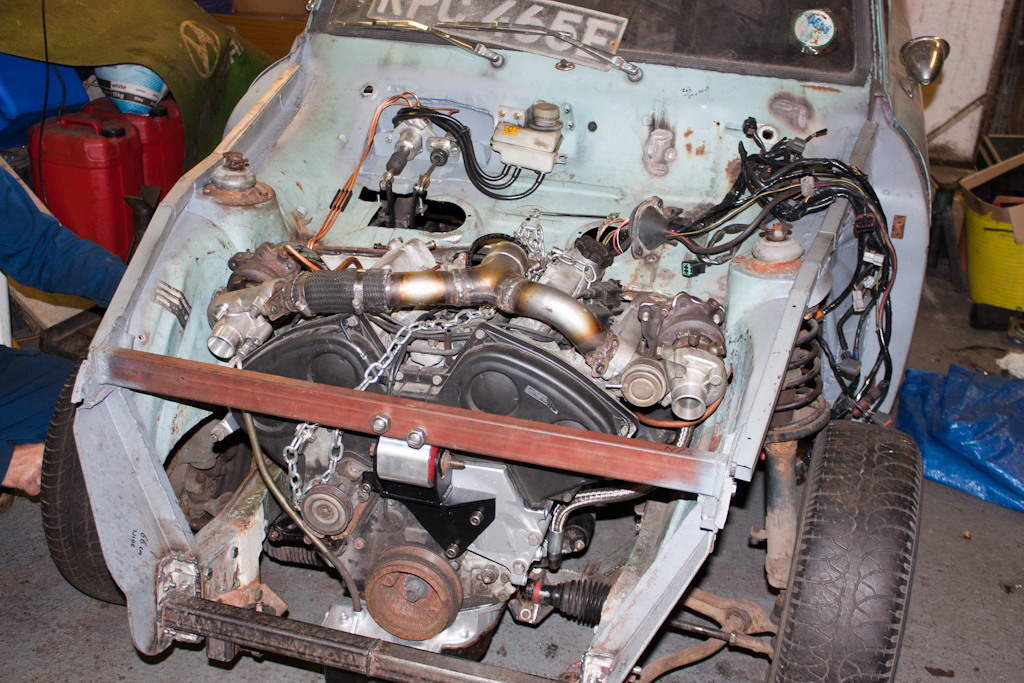
We couldn't.
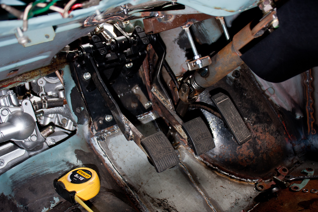
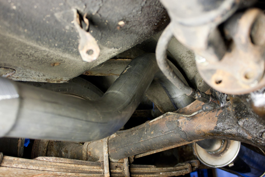
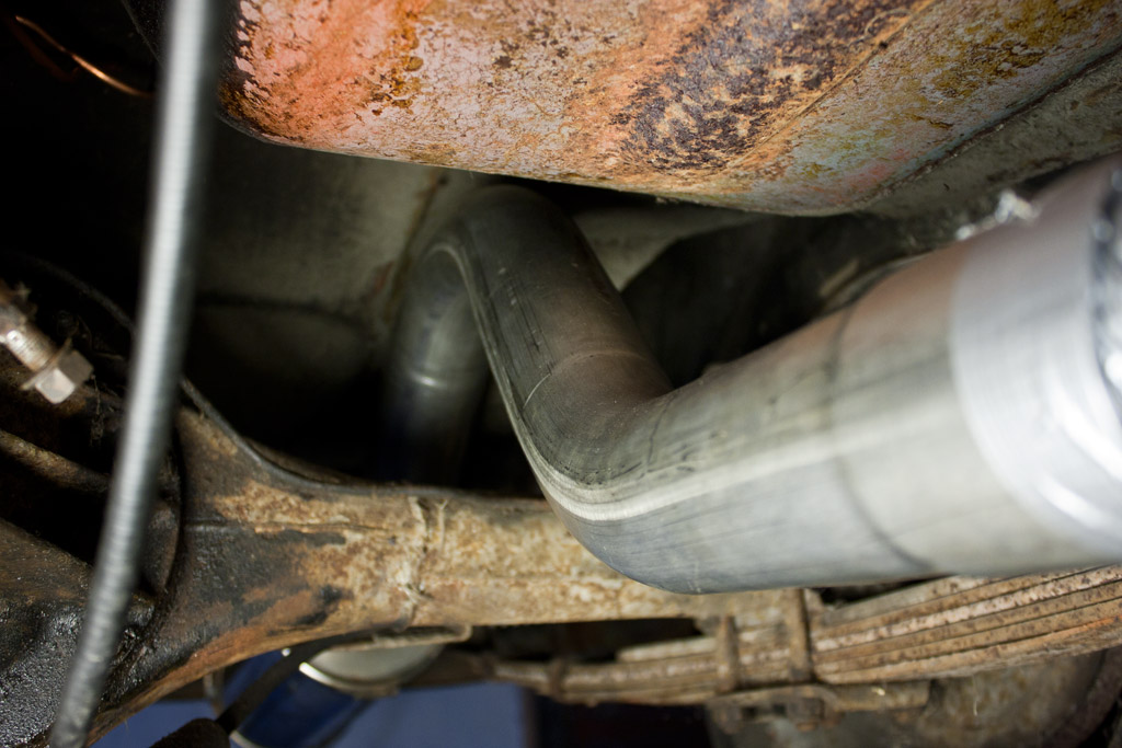
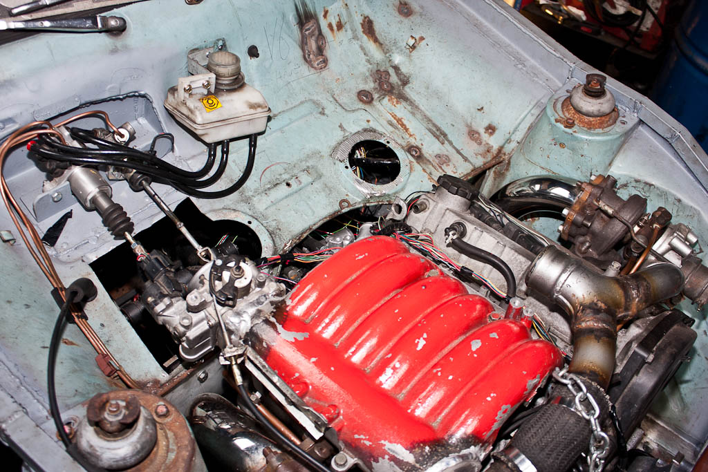
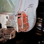
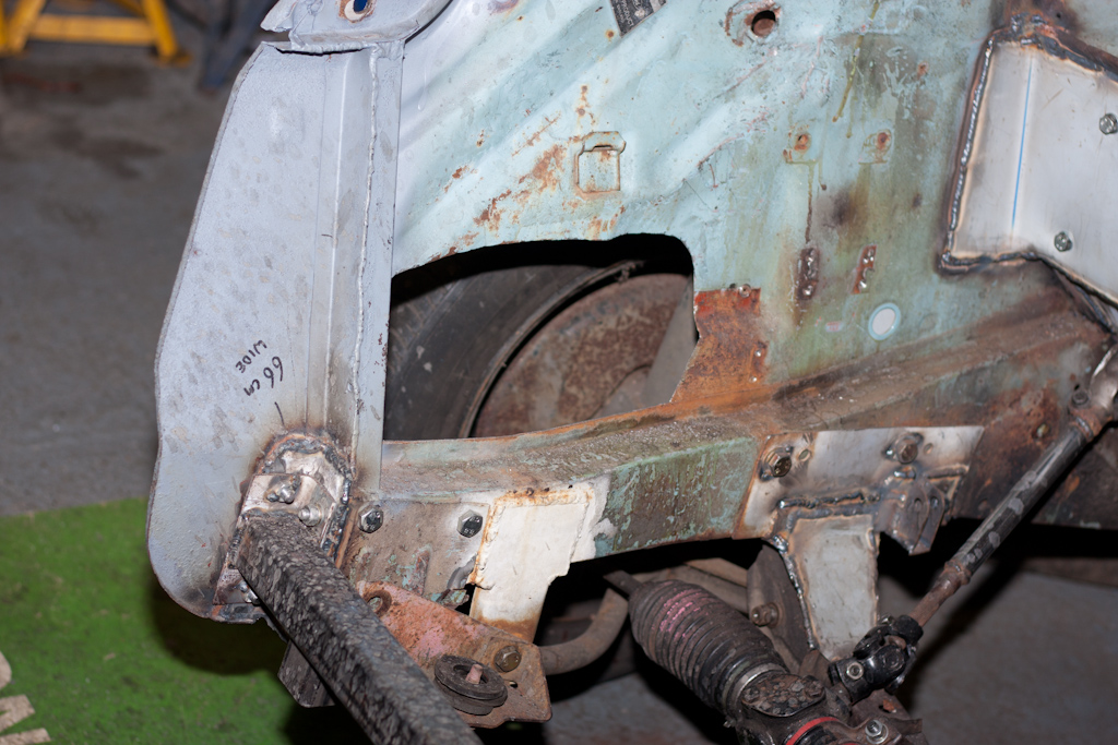
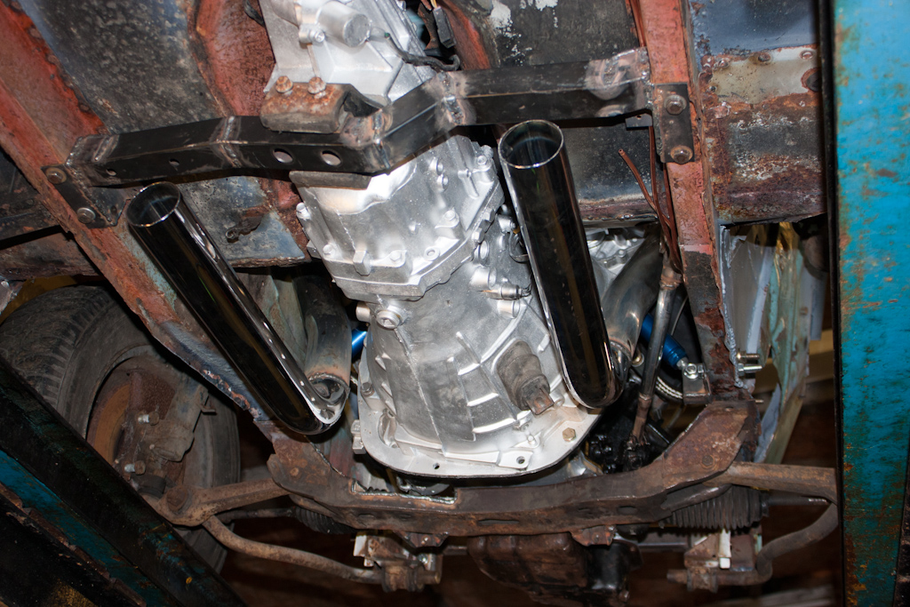
There was not enough movement for the sump to clear the front chassis rail. We'd already decided long ago that we'd remove this and replace it with a bolt-in section, and now seemed the perfect opportunity to do so.
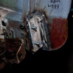
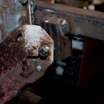
We made some measurements, and went about cutting this front rail out. It went with a small "ping" as the chassis, relieved of tension, sprung apart by about 5mm. Good job we'd measured first!
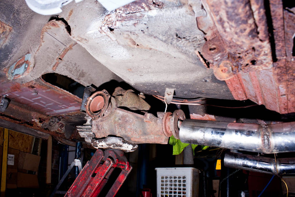
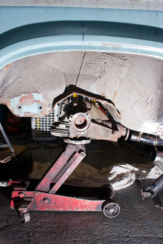
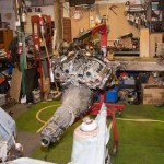
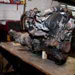
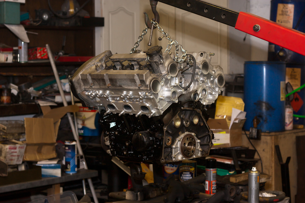
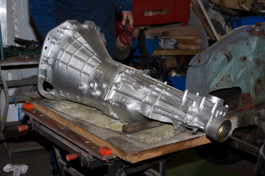
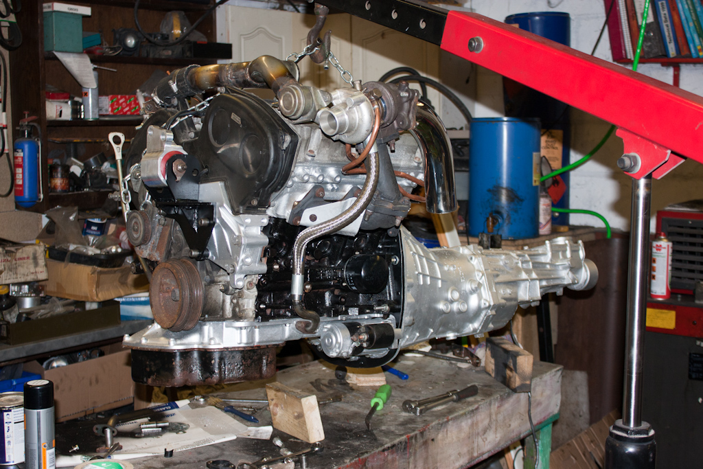
With the bulk removed, we continued lifting the engine and gearbox out.
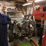
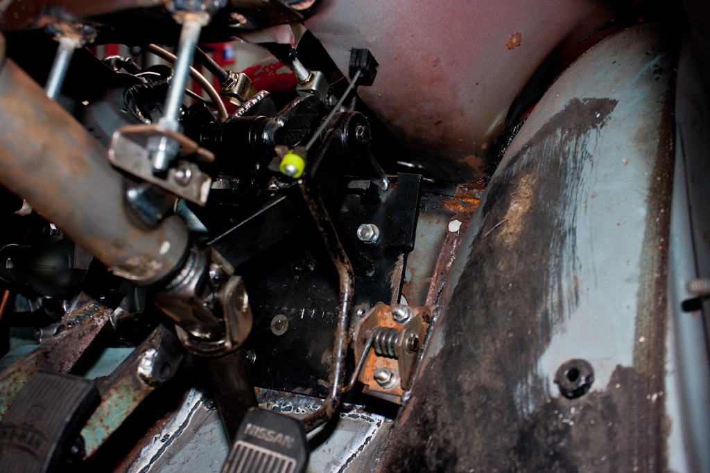
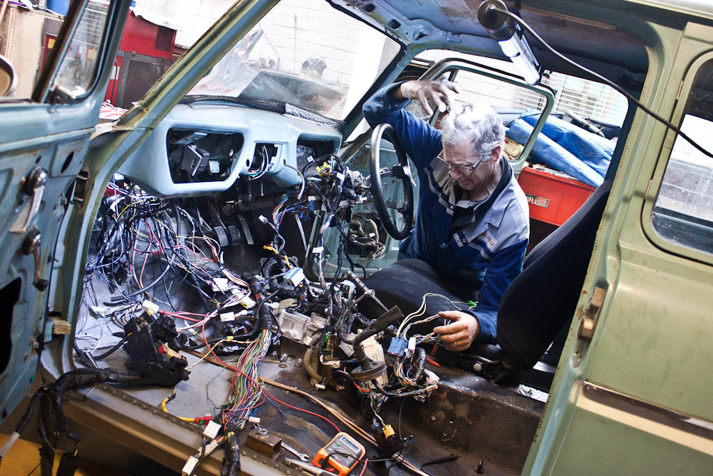
(Excuse my dad's "I'm looking quite smug" look! I was actually sporting one too, but seeing as I was behind the camera, not in front of it...)
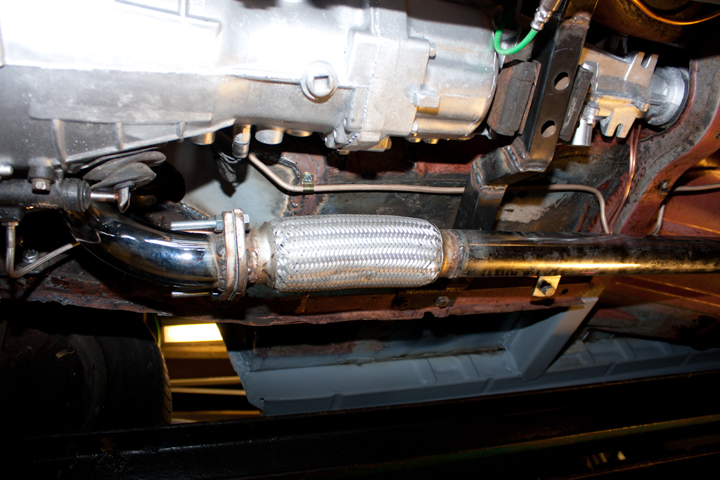
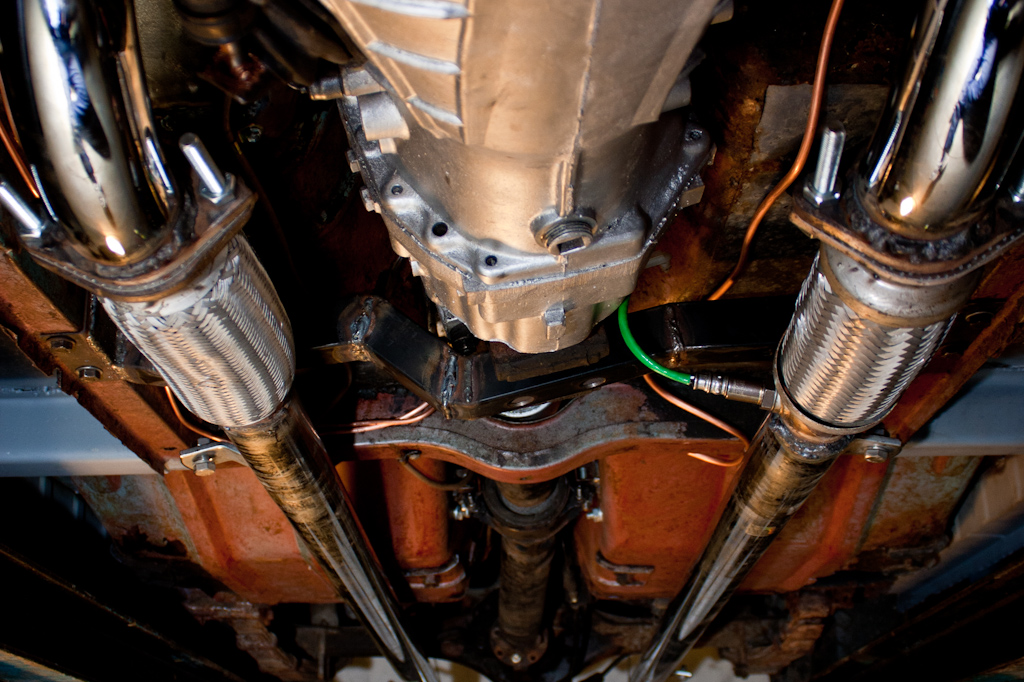
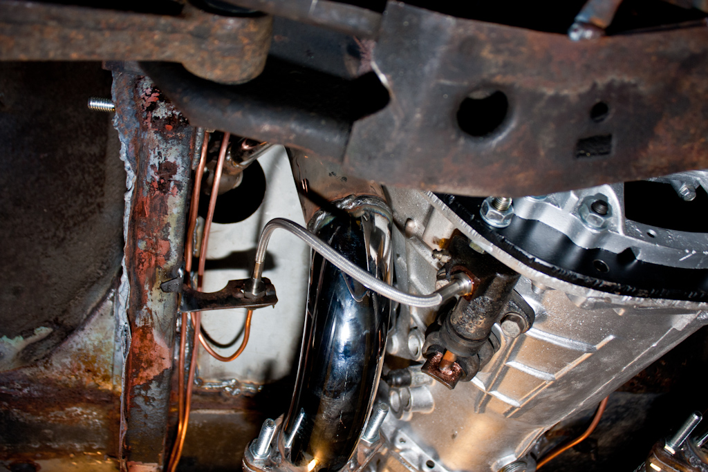
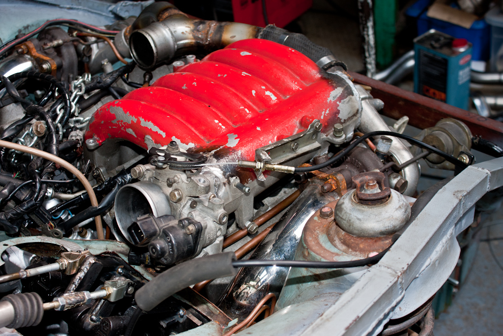
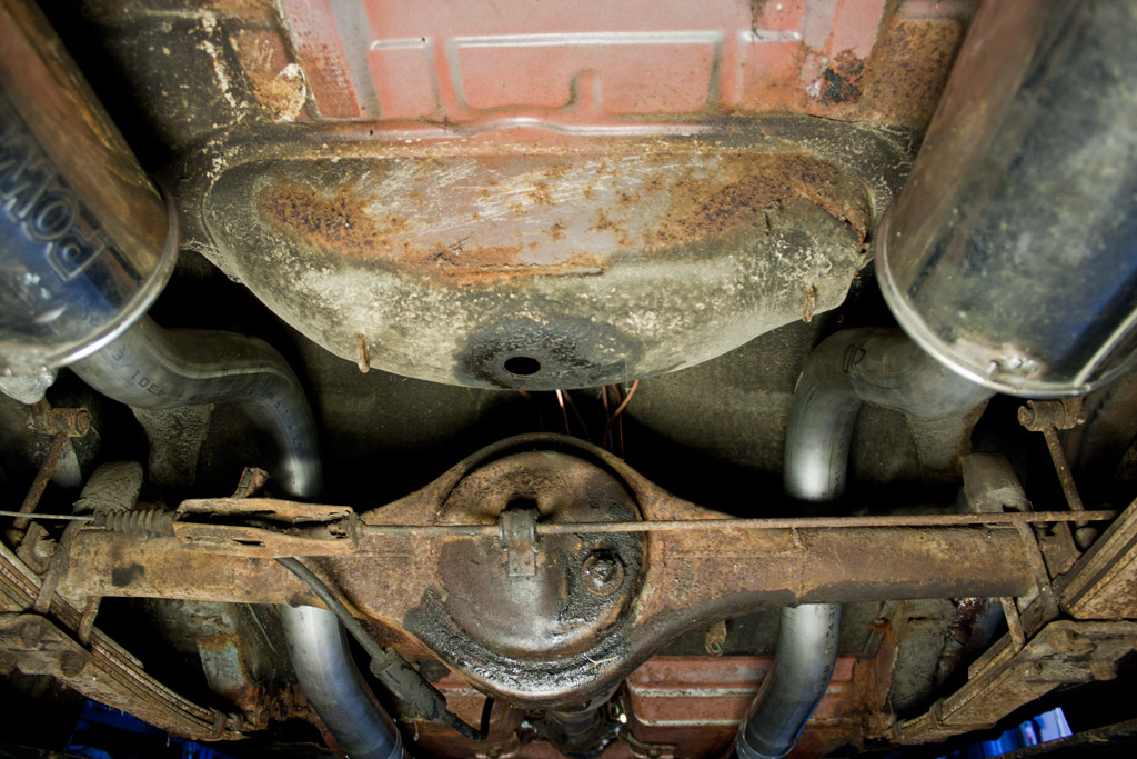
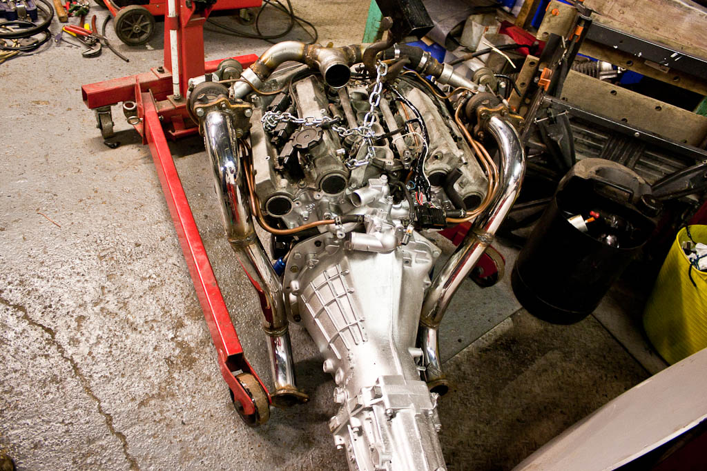
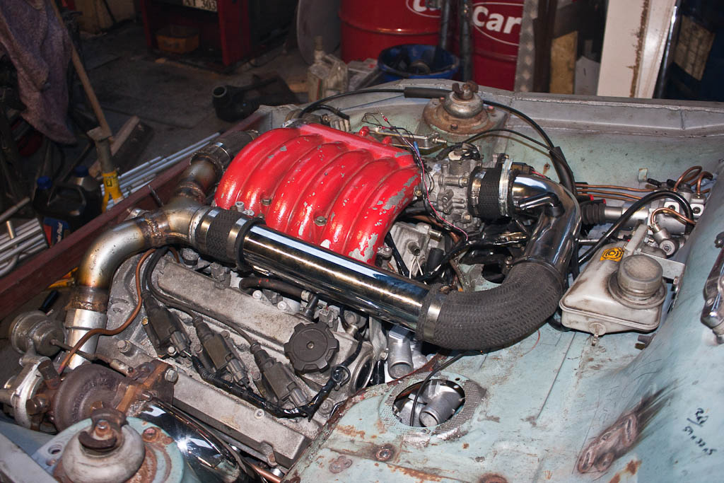
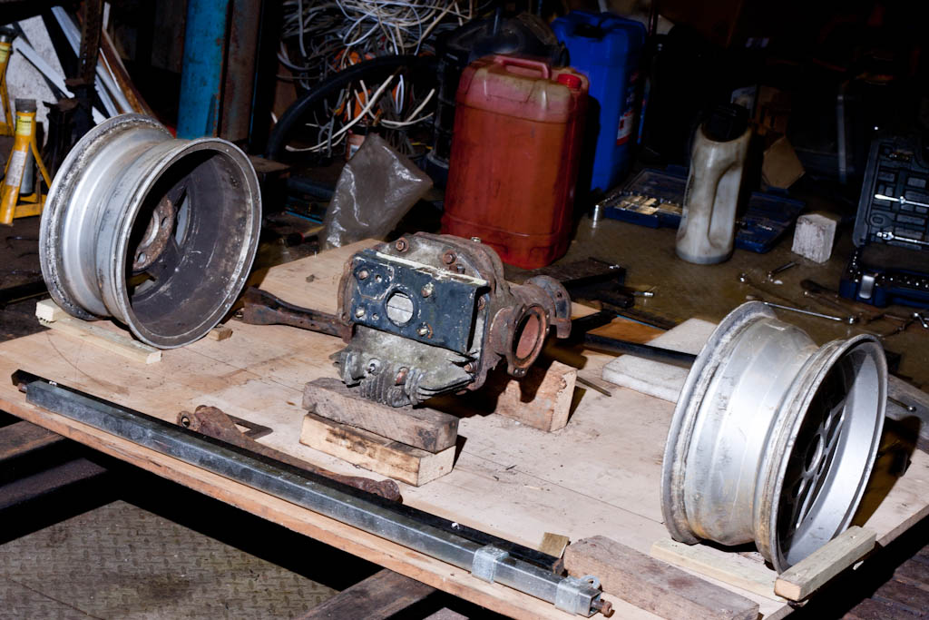
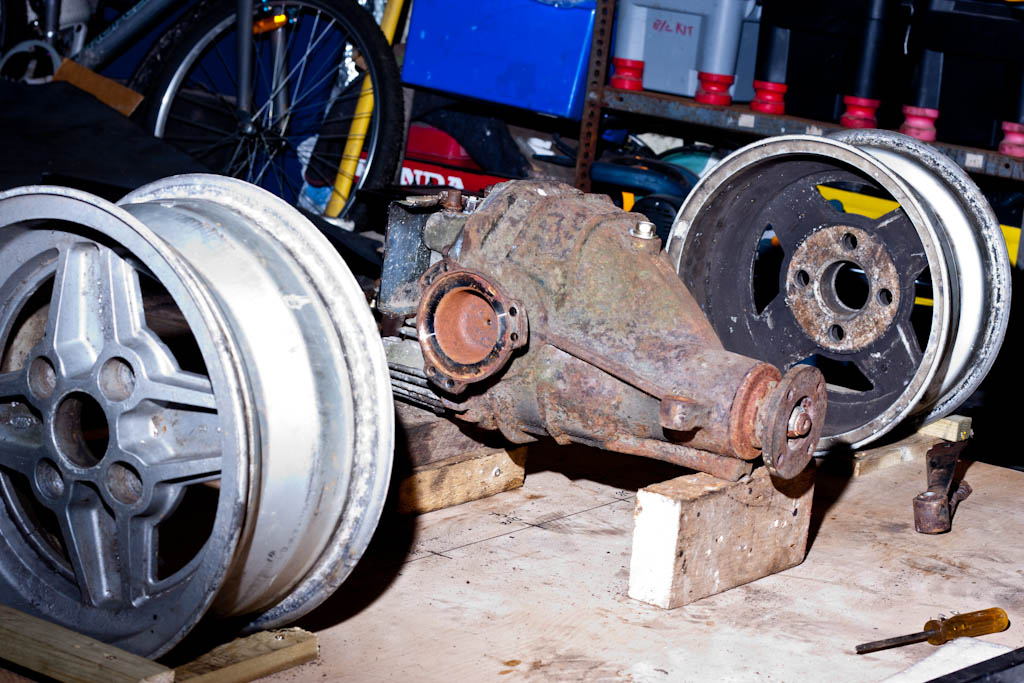
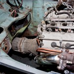
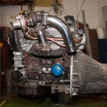
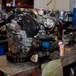
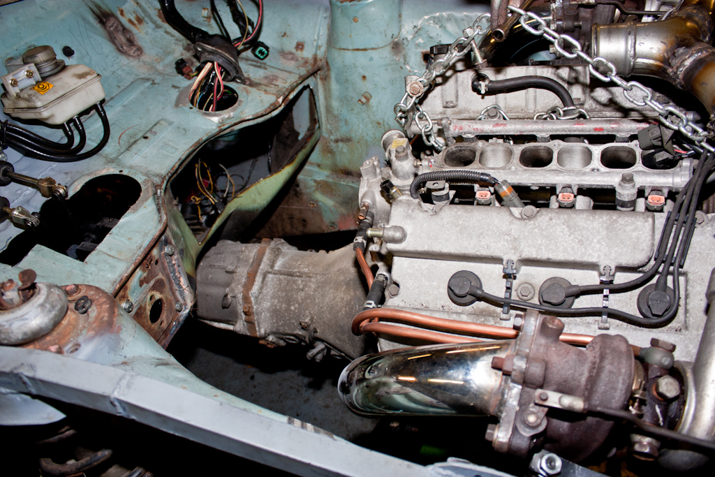
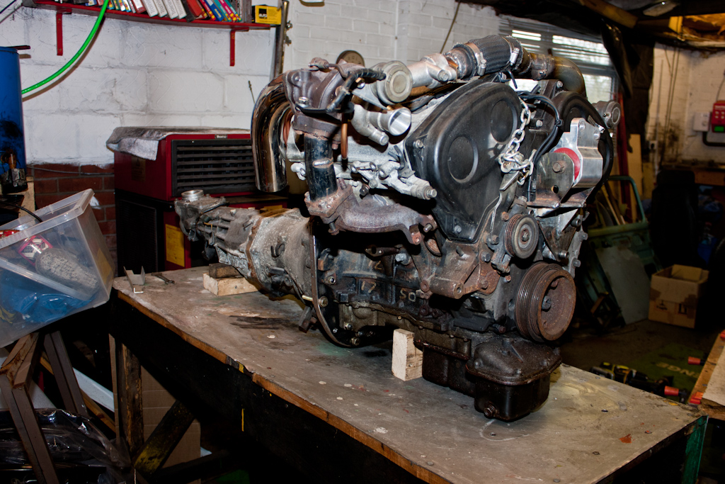
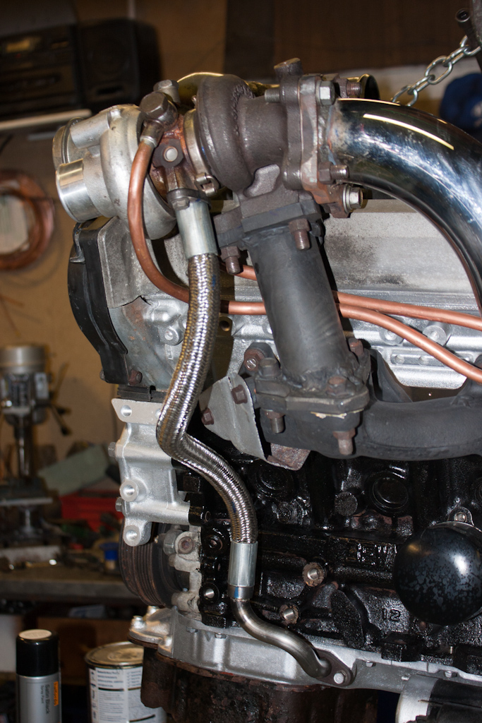
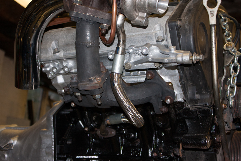
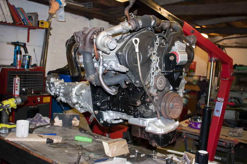
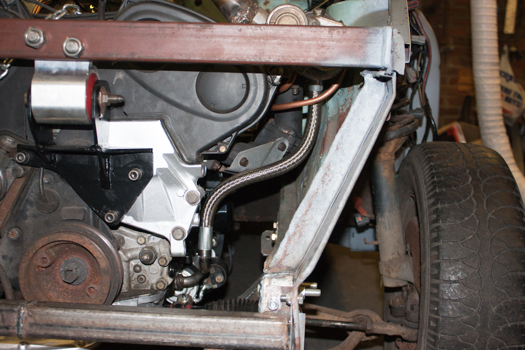
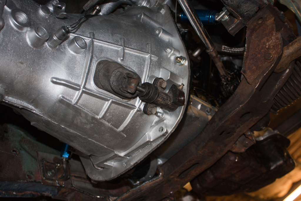
With the engine out, we moved it onto the bench, and could see better the oil filter in place on the side of the block (usually on a VR-4 there is a 90 degree adapter and it's lower down, facing upwards), the turbo coolant pipework, as well as the adapters to move the turbos to a more suitable location.
(Some blatant product placement again... but you can't beat a nice Hobnob and a cup of coffee to keep your strength up!)
With the engine and gearbox safely on the bench, attention turned to putting the strength back into the chassis that we'd cut out earlier.
We began by removing the remaining parts of the original front panel.
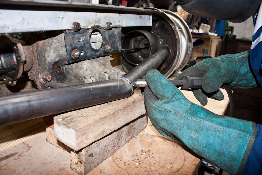
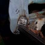
Then made up and welded in place some new bits, along with studs for location and securing.
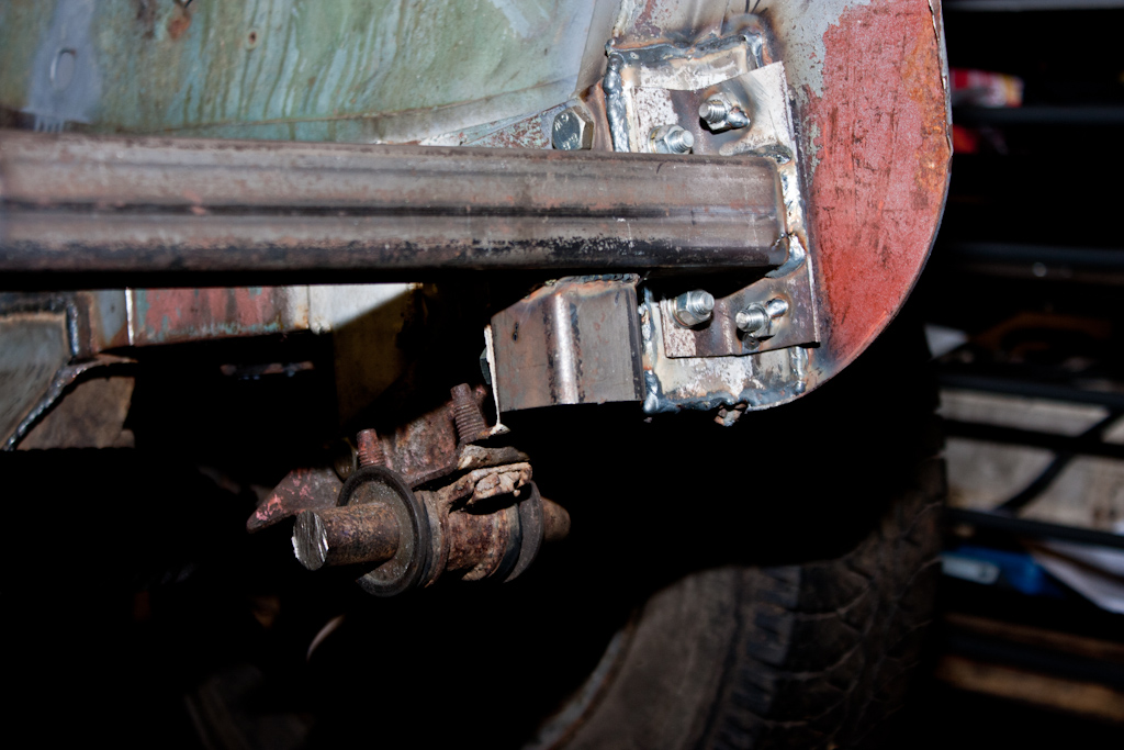
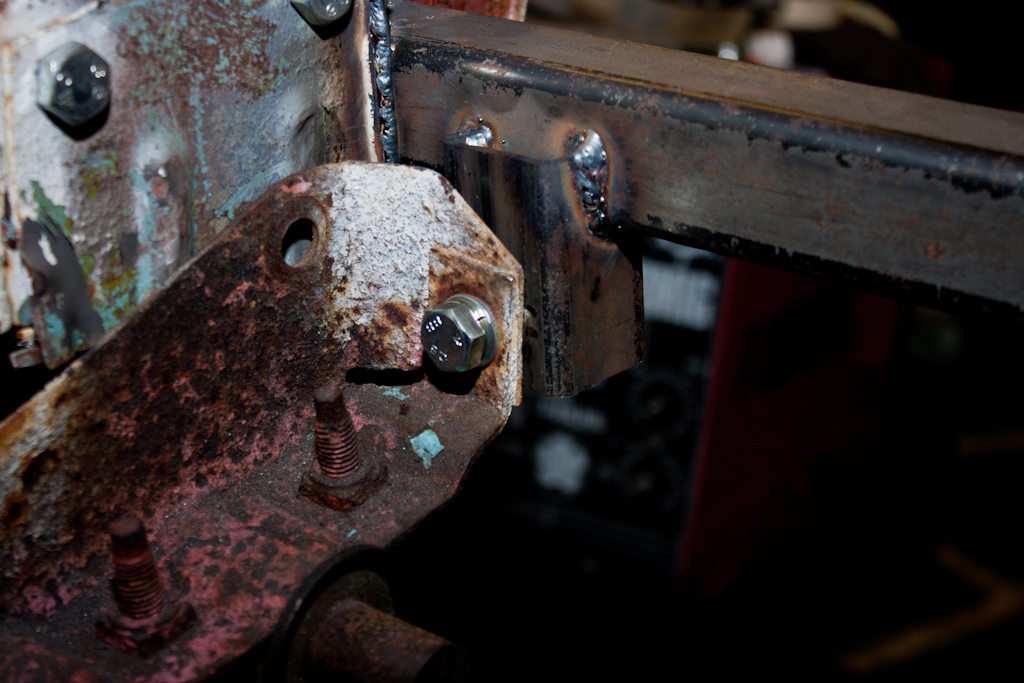
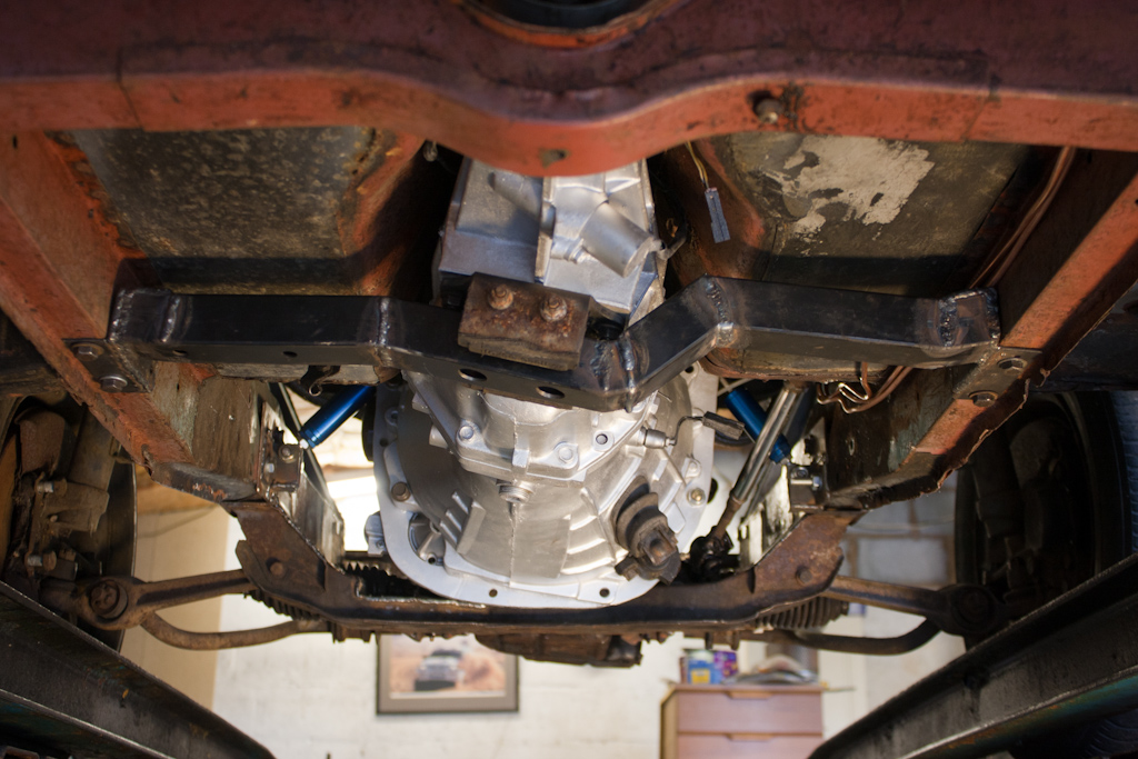
The new crossmember was made up with brackets on the ends.
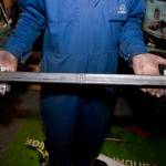
And bolted into place.
This is bolted both from the front, and the sides, and will pull the chassis rails back together to the same measurements they were before removing the original front panel.
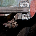
Next, we added some mounts for the anti-roll bar.
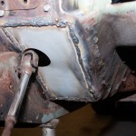
The left-over time today was used to do a little bit of welding to tidy up a previously added panel - the driver's floor pan.
We also added an additional mounting bolt for the suspension crossmember, just behind where we'd added the support for the engine roll-stop mounts (not pictured, but just behind the support to the left of the above photo)
There's minor tweaks that need to take place to the inner wings with a large hammer, there's more pipework for the turbos to be made, and stuff like brake/clutch lines to be made up, and all of this stuff will be much easier with the engine and gearbox not in the way.
We disconnected the wiring from the engine, dropped the front crossmember down to allow us room to move the engine, and decided to see whether we could remove both engine and gearbox as one complete unit.
We couldn't.
There was not enough movement for the sump to clear the front chassis rail. We'd already decided long ago that we'd remove this and replace it with a bolt-in section, and now seemed the perfect opportunity to do so.
We made some measurements, and went about cutting this front rail out. It went with a small "ping" as the chassis, relieved of tension, sprung apart by about 5mm. Good job we'd measured first!
With the bulk removed, we continued lifting the engine and gearbox out.

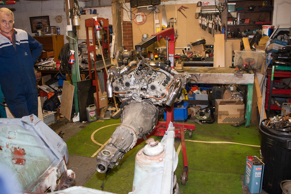
(Excuse my dad's "I'm looking quite smug" look! I was actually sporting one too, but seeing as I was behind the camera, not in front of it...)
With the engine out, we moved it onto the bench, and could see better the oil filter in place on the side of the block (usually on a VR-4 there is a 90 degree adapter and it's lower down, facing upwards), the turbo coolant pipework, as well as the adapters to move the turbos to a more suitable location.

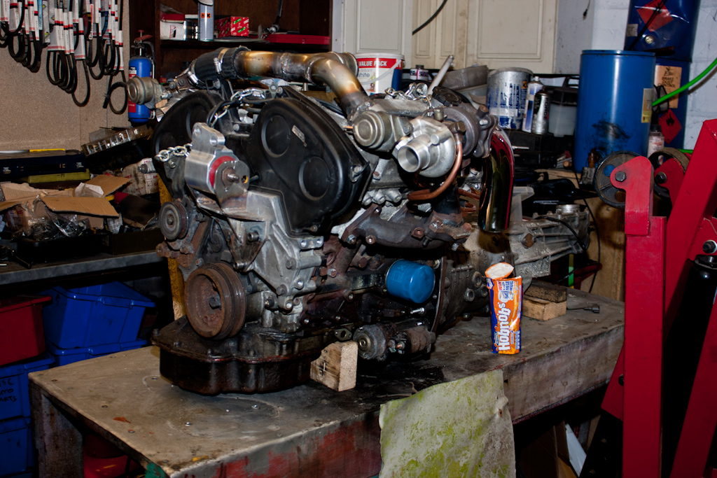
(Some blatant product placement again... but you can't beat a nice Hobnob and a cup of coffee to keep your strength up!)
With the engine and gearbox safely on the bench, attention turned to putting the strength back into the chassis that we'd cut out earlier.
We began by removing the remaining parts of the original front panel.

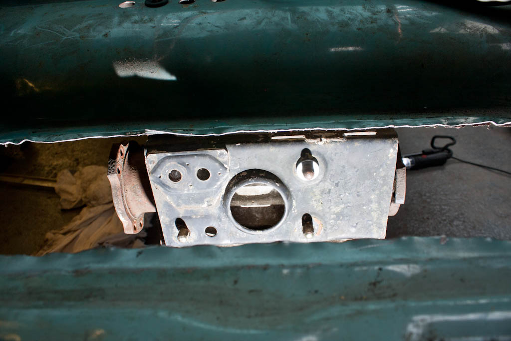
Then made up and welded in place some new bits, along with studs for location and securing.
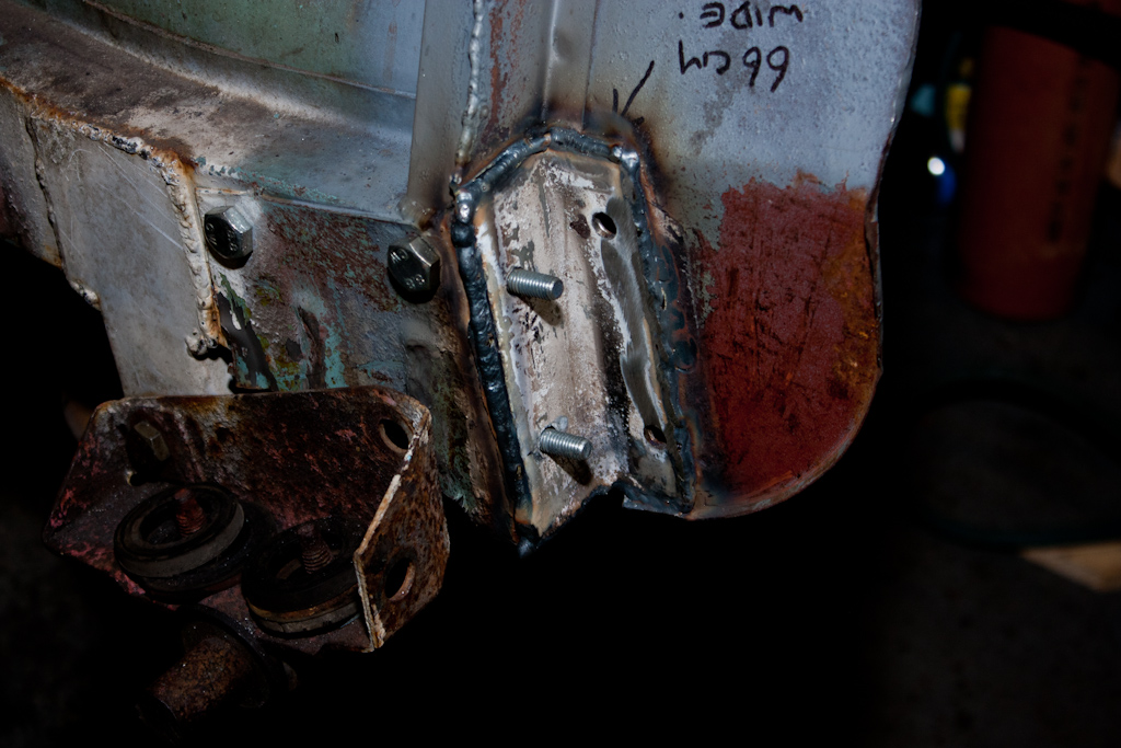
The new crossmember was made up with brackets on the ends.

And bolted into place.
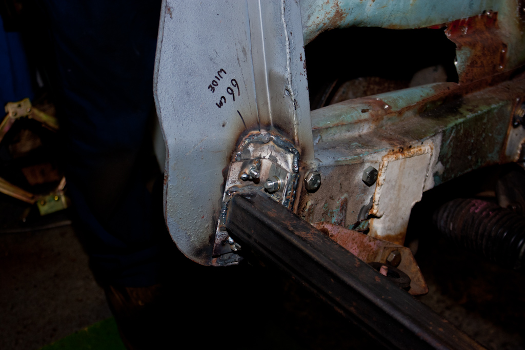
This is bolted both from the front, and the sides, and will pull the chassis rails back together to the same measurements they were before removing the original front panel.
Next, we added some mounts for the anti-roll bar.
The left-over time today was used to do a little bit of welding to tidy up a previously added panel - the driver's floor pan.
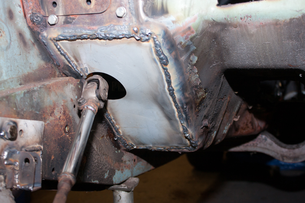
We also added an additional mounting bolt for the suspension crossmember, just behind where we'd added the support for the engine roll-stop mounts (not pictured, but just behind the support to the left of the above photo)
Last edited:
")


")