

You are using an out of date browser. It may not display this or other websites correctly.
You should upgrade or use an alternative browser.
You should upgrade or use an alternative browser.
Anglia Project
- Thread starter Confused
- Start date
More options
Thread starter's postsYeah from the outside it'll look pretty normal. Just a flashy paint job, and some 13" RS alloys.
The engine outputs ~260bhp in the original car, so it should be around that, but it'll only weigh around a ton, and be RWD rather than 4WD as in the original car.
The engine outputs ~260bhp in the original car, so it should be around that, but it'll only weigh around a ton, and be RWD rather than 4WD as in the original car.
Soldato
- Joined
- 23 Nov 2009
- Posts
- 6,041
- Location
- North Leicestershire
Yeah from the outside it'll look pretty normal. Just a flashy paint job, and some 13" RS alloys.
The engine outputs ~260bhp in the original car, so it should be around that, but it'll only weigh around a ton, and be RWD rather than 4WD as in the original car.
Anglia drift car

- Joined
- 3 May 2004
- Posts
- 17,767
- Location
- Democratic People’s Republic of West Surrey
*Sensible hat on*
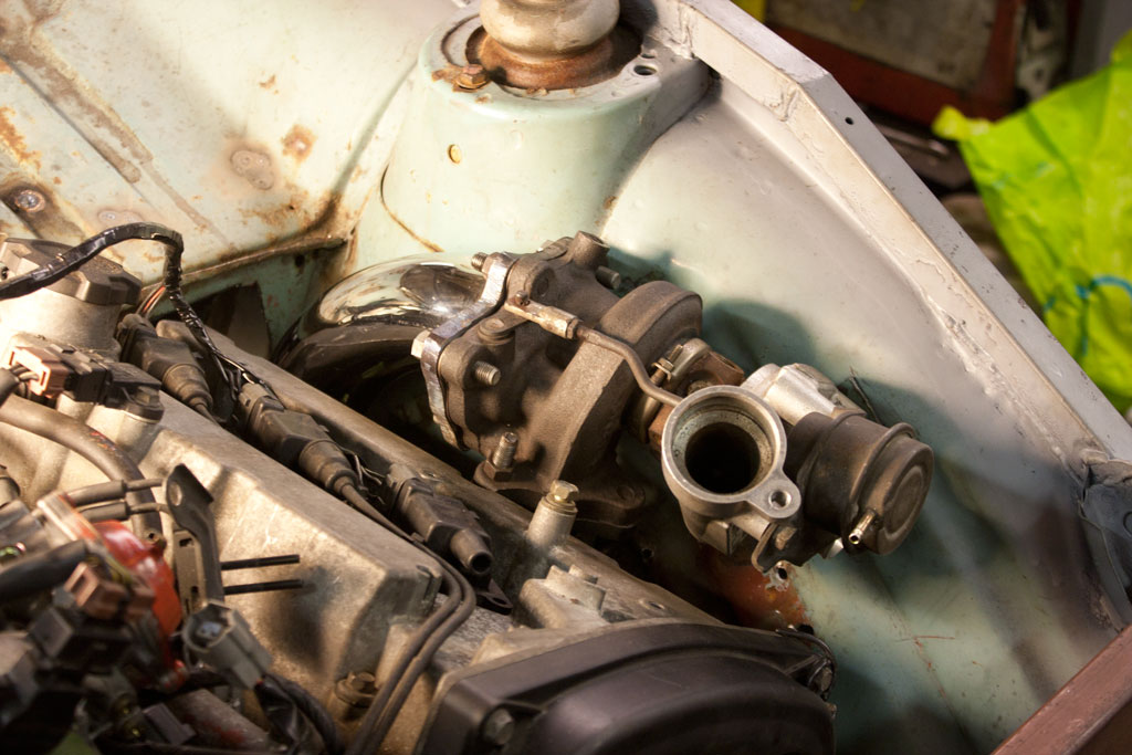
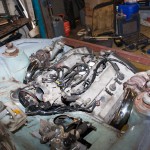
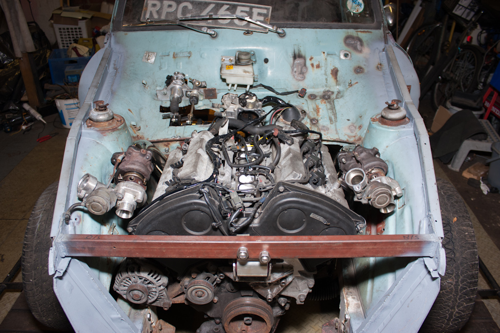
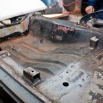
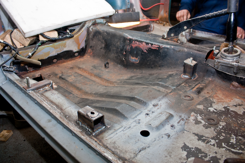
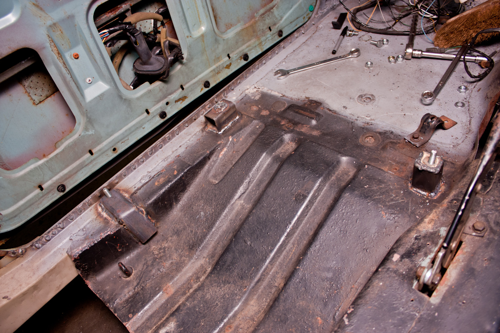
I don't think I like your solution for hanging the engine at the front. I know you've run some box-section down the tops of the inner wings, but there is literally no lateral strength in the front of the car there when you take the wings and front panel off. This pic shows it best:
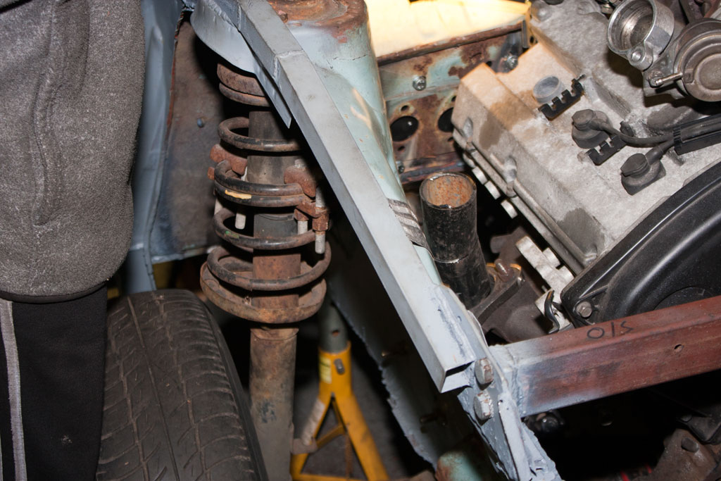
I know from mine if you unbolt that crossmember, you'll still be able to wobble that inner wing about with not too much effort. Because it's bolted away from the end of the box section, it'll still flex once it's bolted up. It'll be putting all that stress into that weld in front of the strut tower. I really think you ought to re-think that so there's a bit of side-to-side rigidity. I'd prefer to see that sat on something directly mounted to the chassis rails, or find a way of mounting it to the original crossmember.
I don't think I like your solution for hanging the engine at the front. I know you've run some box-section down the tops of the inner wings, but there is literally no lateral strength in the front of the car there when you take the wings and front panel off. This pic shows it best:
I know from mine if you unbolt that crossmember, you'll still be able to wobble that inner wing about with not too much effort. Because it's bolted away from the end of the box section, it'll still flex once it's bolted up. It'll be putting all that stress into that weld in front of the strut tower. I really think you ought to re-think that so there's a bit of side-to-side rigidity. I'd prefer to see that sat on something directly mounted to the chassis rails, or find a way of mounting it to the original crossmember.
Hi Jonny,
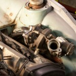
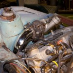
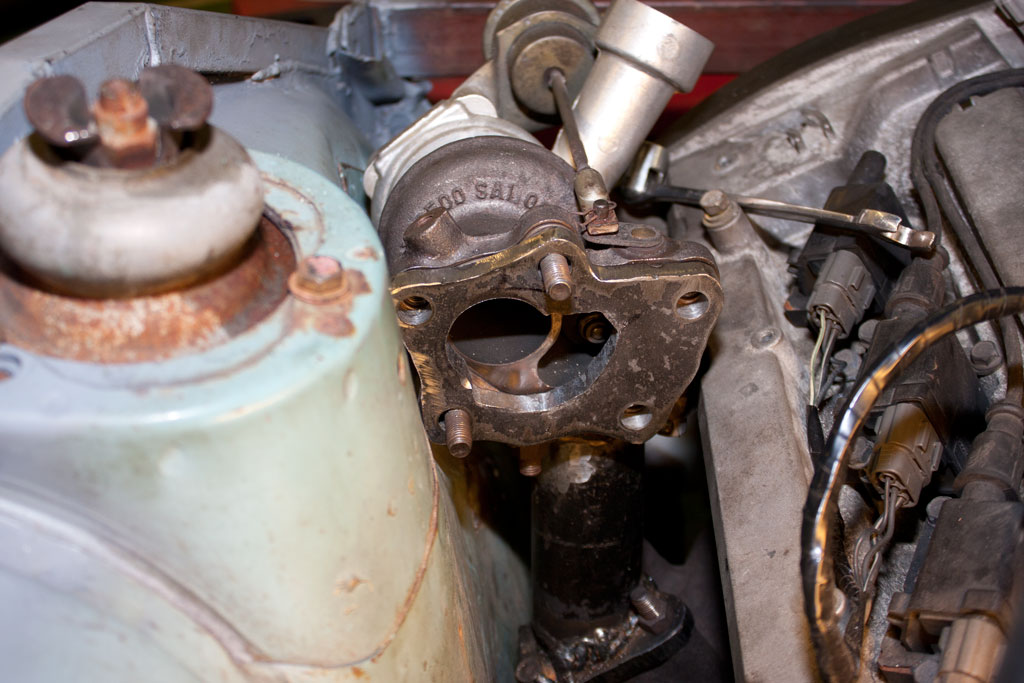
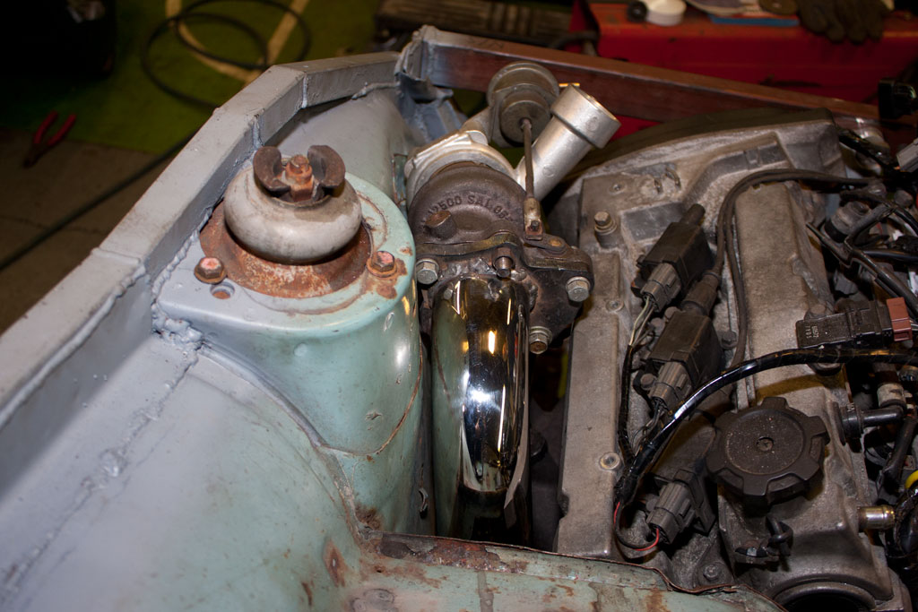
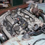
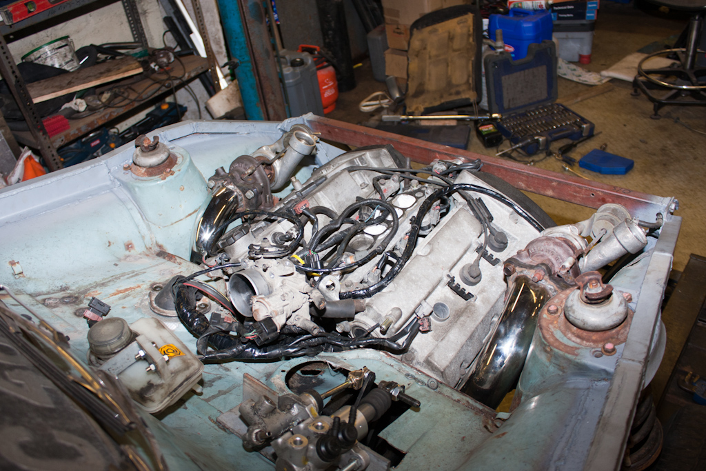
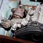
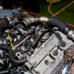
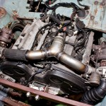
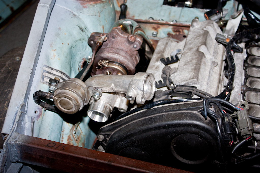
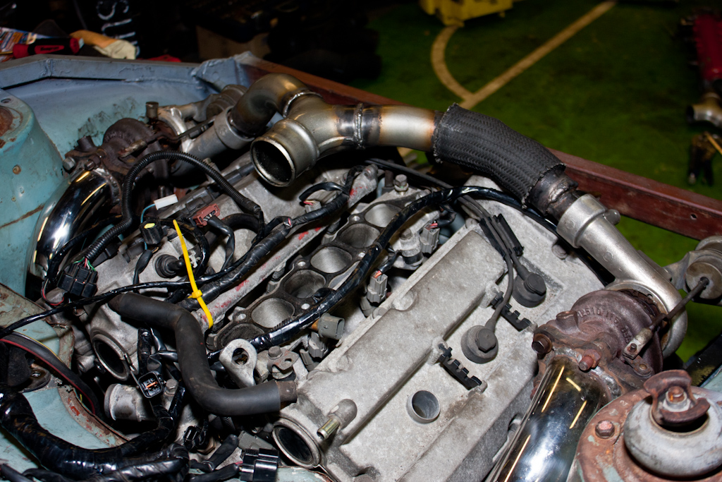
If you look at this picture:
You should be able to see a bit of box section coming up on the angle, just in front of the turbo (in the picture), and is welded to the front panel, and the inner wing. This is also tied in to the chassis rail, and the extra thick bit of steel that is also welded to the end of that bit of open-ended box that you pointed out in the picture you quoted.
If you look at this picture:

You should be able to see a bit of box section coming up on the angle, just in front of the turbo (in the picture), and is welded to the front panel, and the inner wing. This is also tied in to the chassis rail, and the extra thick bit of steel that is also welded to the end of that bit of open-ended box that you pointed out in the picture you quoted.
Last edited:
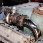
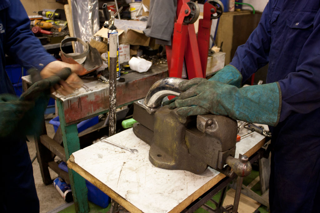
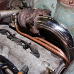
With one downpipe completed, it's time to move the turbo back to the other side, and make another.
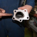
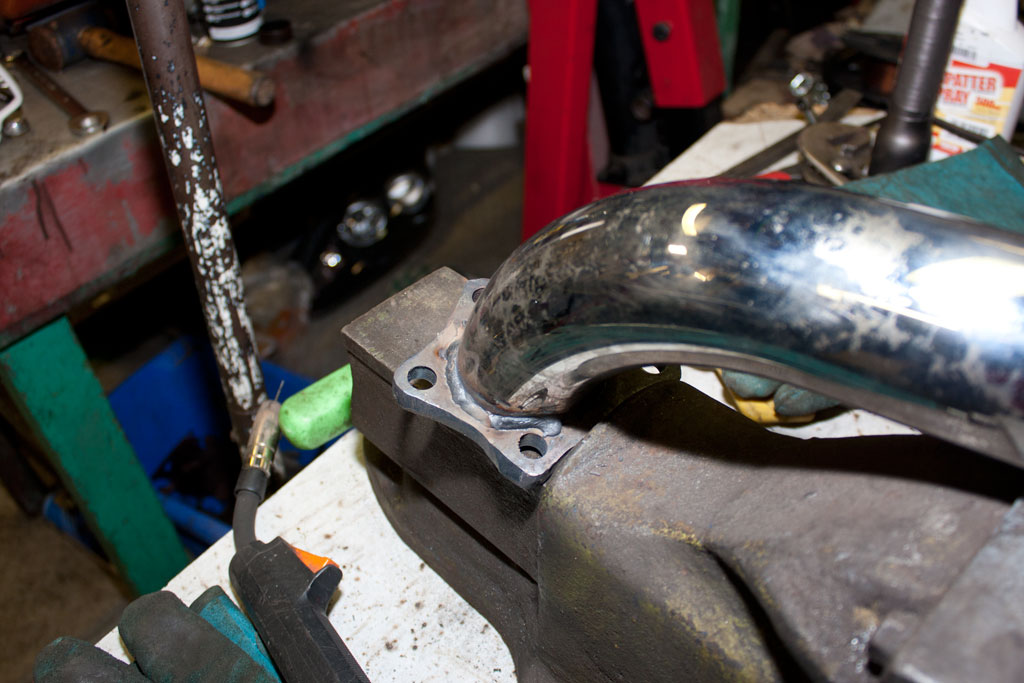
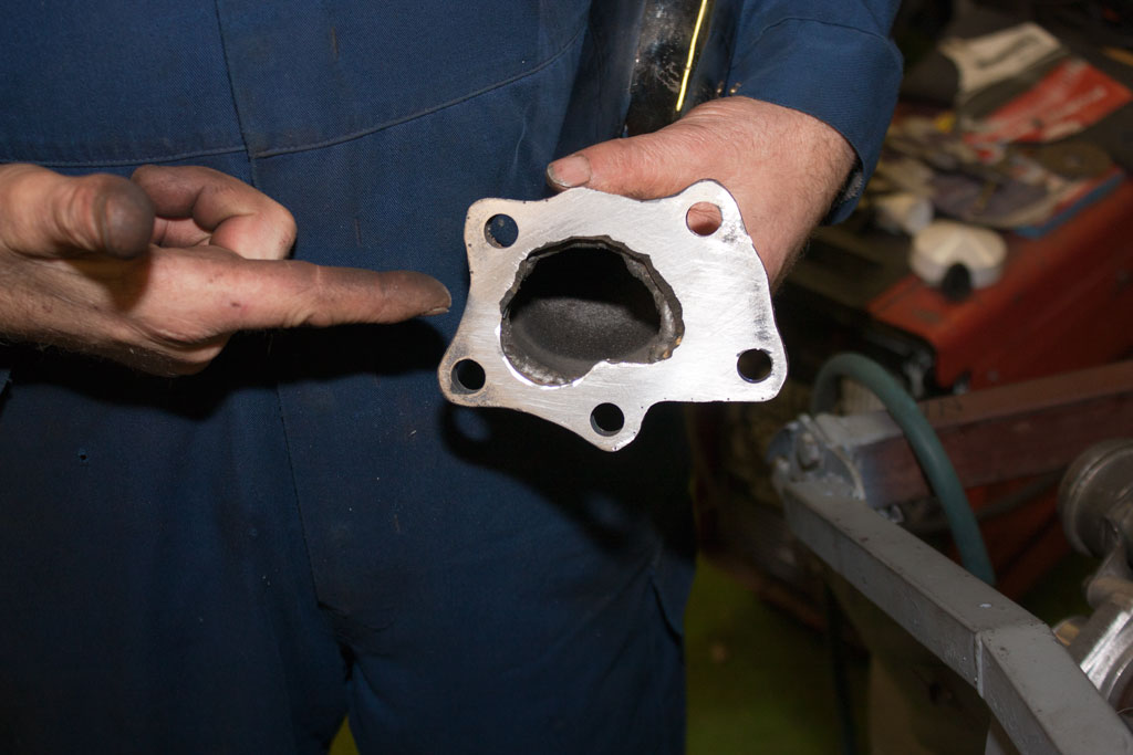
So, one flange marked and hole enlarged to suit and welded together:
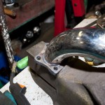
And fitted in place:
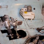
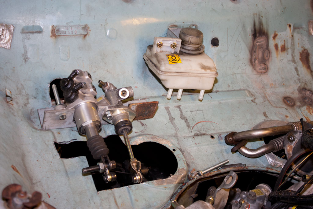
Once that was done, we moved efforts onto the brake/clutch, which we'd started a couple of days ago. We had sitting around brake and clutch master cylinders from a Honda Prelude, so began trying to make them fit. However, the brake master cylinder was too big, and we couldn't get a smooth enough action.
We had to take a trip to the scrapyard to get rid of some old junk, so we did our "Scrapheap Challenge" bit and looked around, and came back with a brake master cylinder from a 2001 Fiat Punto, which wasn't as long, and, we made up a bracket to hold them in place. Also from the Punto came the reservoir, which is shared between brake and clutch - which means less things to fit into the engine bay on the Anglia!
So, one flange marked and hole enlarged to suit and welded together:
And fitted in place:
Once that was done, we moved efforts onto the brake/clutch, which we'd started a couple of days ago. We had sitting around brake and clutch master cylinders from a Honda Prelude, so began trying to make them fit. However, the brake master cylinder was too big, and we couldn't get a smooth enough action.
We had to take a trip to the scrapyard to get rid of some old junk, so we did our "Scrapheap Challenge" bit and looked around, and came back with a brake master cylinder from a 2001 Fiat Punto, which wasn't as long, and, we made up a bracket to hold them in place. Also from the Punto came the reservoir, which is shared between brake and clutch - which means less things to fit into the engine bay on the Anglia!

Last edited:
This will be the final update from the week of work on the Anglia, so we finished the week by finishing up a couple of bits that had been partly started.
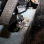
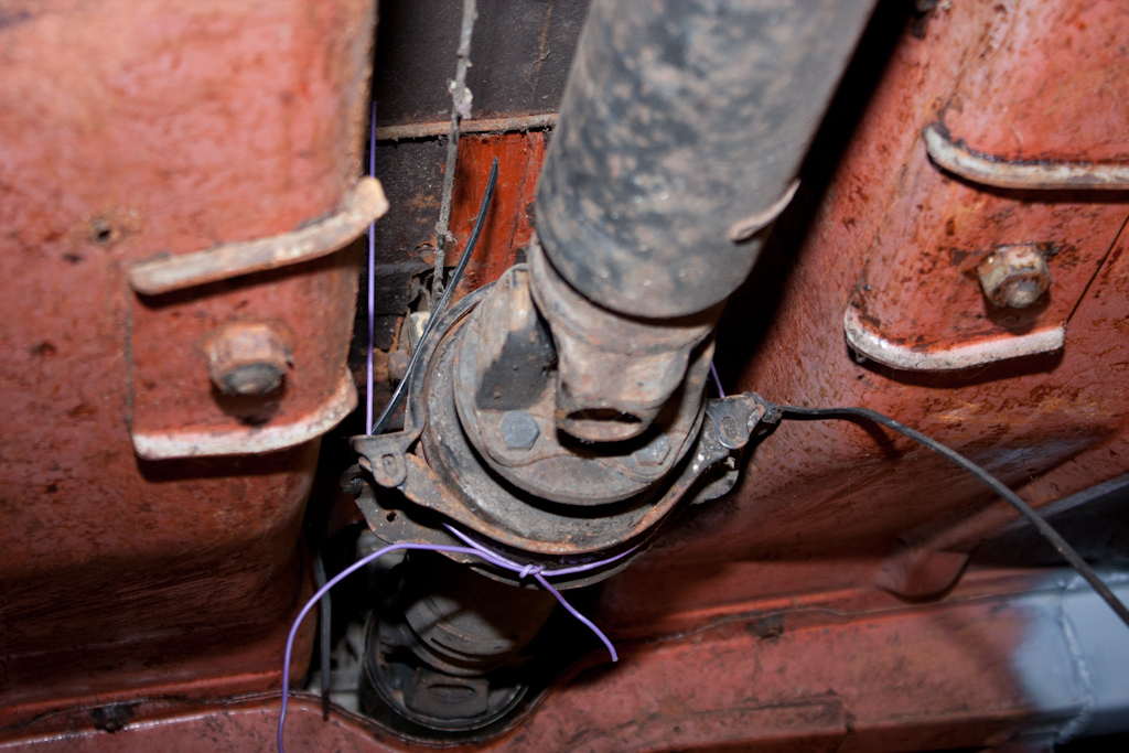
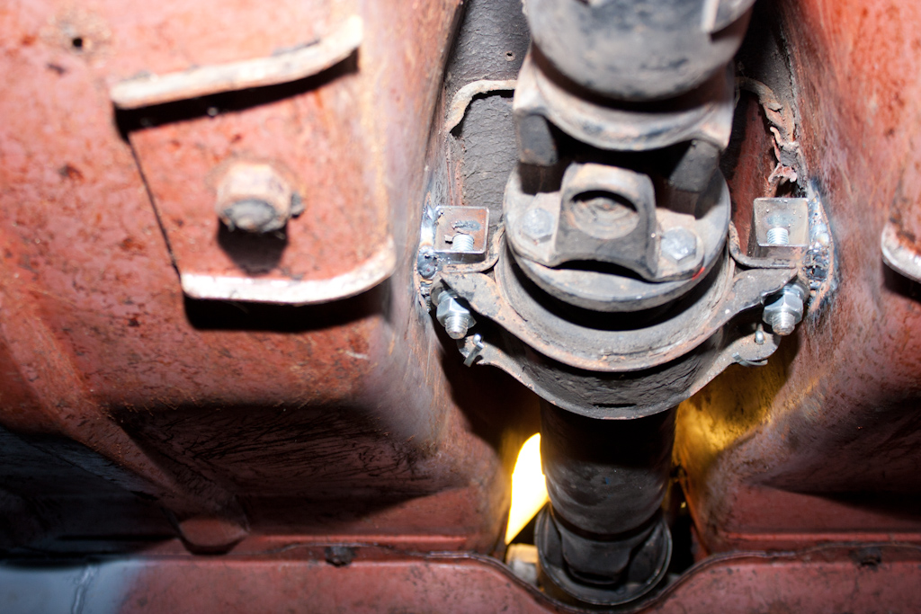
First off, the propshaft. The Nissan propshaft was the perfect length to mate up the gearbox and the standard Anglia rear axle, but it wasn't supported at it's centre joint, well, other than by a small piece of electrical wire!
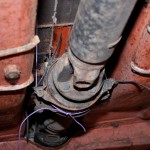
A more permanent solution was required, so a couple of small bits of box section, with a bolt welded in place, and then welded to the inside of the transmission tunnel should do the trick:
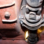
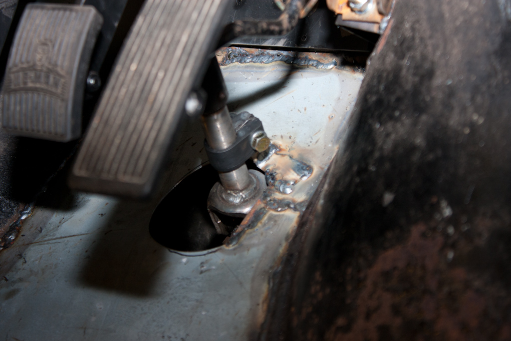
Moving into the car, and the steering shaft needed supporting between two of the joints. A simple bracket, and that was done:
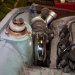
I also managed to pick up another rear turbo and manifold, as well as a manual throttle body, which doesn't have the Traction Control stuff on the side of it. We bolted the turbos into place, and we could now see how the space was being used up quite quickly!
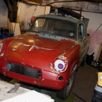
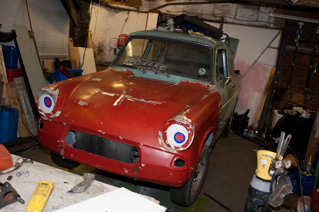
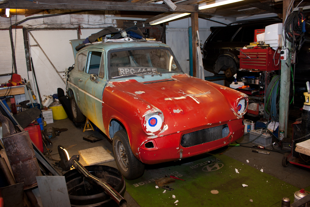
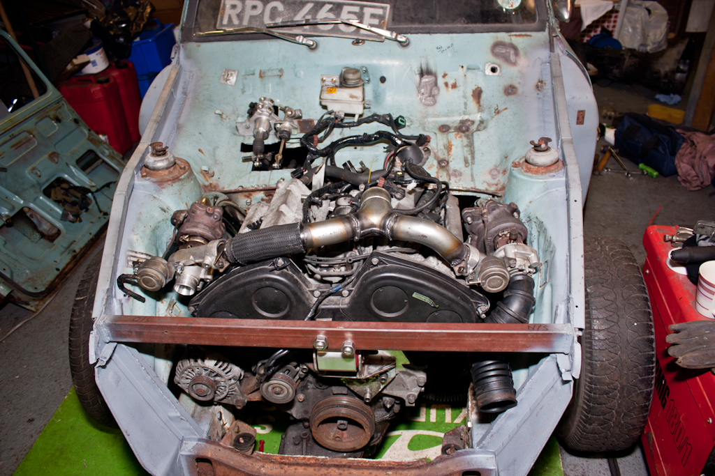
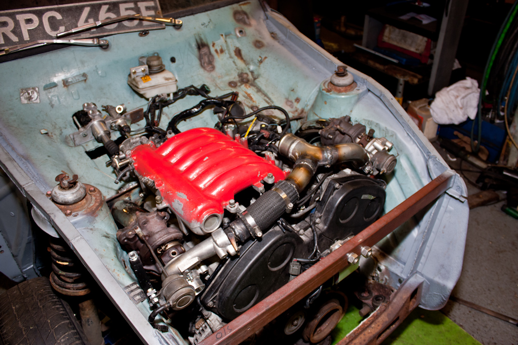
During the making of the pipework for the turbos, we decided to drag the fibreglass flip front out, and put it on the car, to ensure we'd have the required clearance under the bonnet for the myriad of pipework that will be required. So, here's a couple of photos of it looking somewhat more like a normal Ford Anglia.
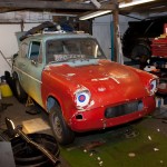
Unfortunately the current schedule of visits every 4 weeks means that the next scheduled visit falls on the weekend Christmas, so no work will get done then! So, you'll have to tune in at the end of January for the next instalment!
First off, the propshaft. The Nissan propshaft was the perfect length to mate up the gearbox and the standard Anglia rear axle, but it wasn't supported at it's centre joint, well, other than by a small piece of electrical wire!
A more permanent solution was required, so a couple of small bits of box section, with a bolt welded in place, and then welded to the inside of the transmission tunnel should do the trick:
Moving into the car, and the steering shaft needed supporting between two of the joints. A simple bracket, and that was done:
I also managed to pick up another rear turbo and manifold, as well as a manual throttle body, which doesn't have the Traction Control stuff on the side of it. We bolted the turbos into place, and we could now see how the space was being used up quite quickly!

During the making of the pipework for the turbos, we decided to drag the fibreglass flip front out, and put it on the car, to ensure we'd have the required clearance under the bonnet for the myriad of pipework that will be required. So, here's a couple of photos of it looking somewhat more like a normal Ford Anglia.
Unfortunately the current schedule of visits every 4 weeks means that the next scheduled visit falls on the weekend Christmas, so no work will get done then! So, you'll have to tune in at the end of January for the next instalment!
Last edited:
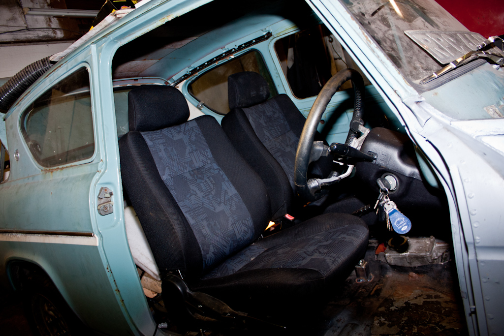
Continuing the tradition of "do something when we think about it", the next thing we decided to tackle was the seats.
Going to the magical store room of bits that my dad has acquired over the years, we managed to find a pair of seats that were originally in a Mitsubishi Lancer Evolution VI, that were removed by Ralliart when they fitted the Recaro seats prior to selling them through the UK dealer networks.
So, we measured up, marked, measured up again, cut, put in place, and bolted/welded some supports to the floor, which will both reinforce where the seats will sit, and also allow the seat to be both level, square, and moveable.

This then allowed the seats to be put in place, and bolted down securely.

Attention next moved to the engine again, and the eternal question that we've been asking since deciding to use this engine... how are we going to actually plumb in all of the inlet pipework!?
I've been wanting to put an intercooler at the front of the car, not only does it look cool, but it will keep the inlet temperatures down. Which would mean combining the output from the two turbos, installing the intercooler, piping to and from it, and then round to the inlet on the back of the engine. Not to mention, that the pipework from the filter to the turbos also has to be put in place!
However, putting my sensible hat on, this is not going to be a track car, this is not going to be used at full power for prolonged periods (there's nowhere other than a track where I could potentially even use it for those purposes!) - so a decision was made to do away with the intercooler.
This made the decision on the pipework much simper - it wouldn't need to come down to the front of the car, so that space can be free up for pre-turbo pipework, and more essential stuff like a coolant radiator and fans!
To that end, we got to work.
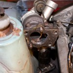
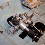
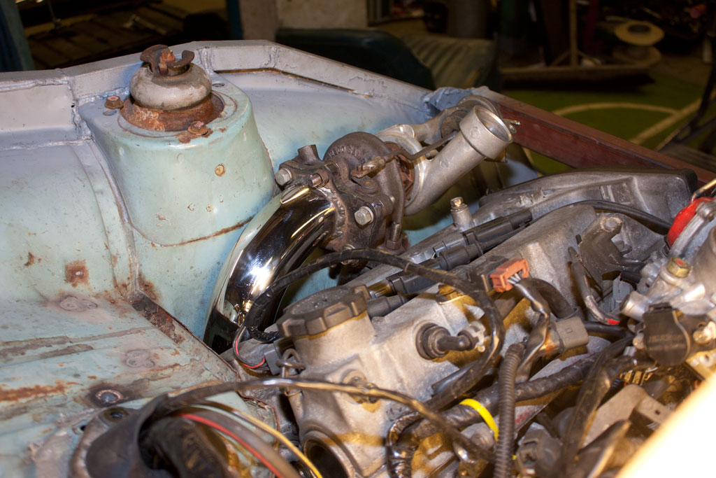
First off was to turn the compressor side of the driver's side turbo round, and making up a bracket to hold the wastegate actuator in the correct place.
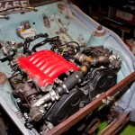
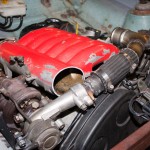
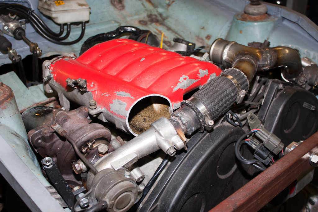
From the original VR4, I had the Y pipe that usually runs across the top of the engine, and I also acquired another. These got chopped up for bits, and a new Y pipe was made, bringing the outlet from both turbos to the centre of the engine, to head to the back, ready to loop round and into the throttle body.
As they say, a picture is worth a thousand words...
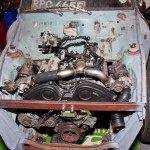
A couple of brackets will need to be removed from the intake plenum so that it will sit down flush, but that'll be a task for next time.
Going to the magical store room of bits that my dad has acquired over the years, we managed to find a pair of seats that were originally in a Mitsubishi Lancer Evolution VI, that were removed by Ralliart when they fitted the Recaro seats prior to selling them through the UK dealer networks.
So, we measured up, marked, measured up again, cut, put in place, and bolted/welded some supports to the floor, which will both reinforce where the seats will sit, and also allow the seat to be both level, square, and moveable.
This then allowed the seats to be put in place, and bolted down securely.
Attention next moved to the engine again, and the eternal question that we've been asking since deciding to use this engine... how are we going to actually plumb in all of the inlet pipework!?
I've been wanting to put an intercooler at the front of the car, not only does it look cool, but it will keep the inlet temperatures down. Which would mean combining the output from the two turbos, installing the intercooler, piping to and from it, and then round to the inlet on the back of the engine. Not to mention, that the pipework from the filter to the turbos also has to be put in place!
However, putting my sensible hat on, this is not going to be a track car, this is not going to be used at full power for prolonged periods (there's nowhere other than a track where I could potentially even use it for those purposes!) - so a decision was made to do away with the intercooler.
This made the decision on the pipework much simper - it wouldn't need to come down to the front of the car, so that space can be free up for pre-turbo pipework, and more essential stuff like a coolant radiator and fans!
To that end, we got to work.
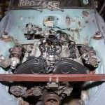
First off was to turn the compressor side of the driver's side turbo round, and making up a bracket to hold the wastegate actuator in the correct place.
From the original VR4, I had the Y pipe that usually runs across the top of the engine, and I also acquired another. These got chopped up for bits, and a new Y pipe was made, bringing the outlet from both turbos to the centre of the engine, to head to the back, ready to loop round and into the throttle body.
As they say, a picture is worth a thousand words...


A couple of brackets will need to be removed from the intake plenum so that it will sit down flush, but that'll be a task for next time.
Last edited:
Although it's hardly happened so far, which I for one am exceptionally surprised about, something that we've done hasn't been quite right, and could be improved upon.
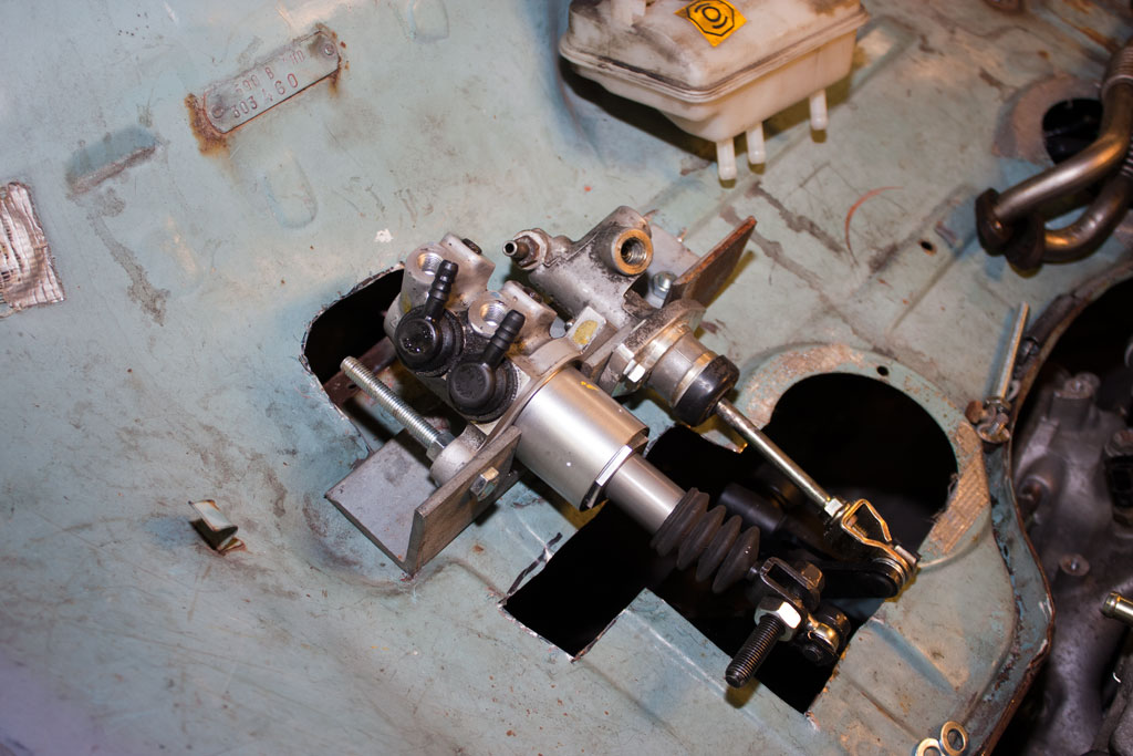
This something was the brake & clutch master cylinders.
The place we'd positioned them previously meant that the movement on the arms from the pedals wasn't entirely smooth, and there was little space between them and the throttle body, so getting some kind of pipework onto the throttle body would have proved very difficult.
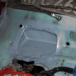
Therefore, it was decided to move them, and do our most major bit of bodywork refabrication to date.
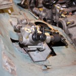
A section of the bulkhead was cut out, and a new bit welded in which will allow the master cylinders to be recessed slightly, and further back.
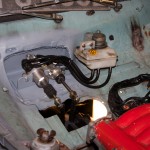
This brought the arms from the pedals to a more upright position, and is acting more directly on the pistons within the cylinders. It also gives more clearance between the throttle body and the pedal arms, which was then improved further, by a few modifications to the inlet plenum.
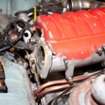
Due to the reorientation of the turbo and the inlet pipework, the plenum required a few brackets removing, and an end chopped off, so that it will sit fully down onto the engine. A small amount was taken from the end where the throttle body is, to angle the throttle body upwards slightly, again giving more clearance for the intake pipework to fit.
The plenum will be taken to be welded up fully soon.
Some water pipes were also made up on both sides of the engine for cooling of the turbos.
This something was the brake & clutch master cylinders.
The place we'd positioned them previously meant that the movement on the arms from the pedals wasn't entirely smooth, and there was little space between them and the throttle body, so getting some kind of pipework onto the throttle body would have proved very difficult.
Therefore, it was decided to move them, and do our most major bit of bodywork refabrication to date.
A section of the bulkhead was cut out, and a new bit welded in which will allow the master cylinders to be recessed slightly, and further back.
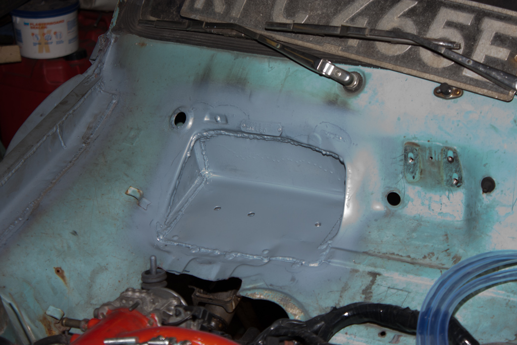
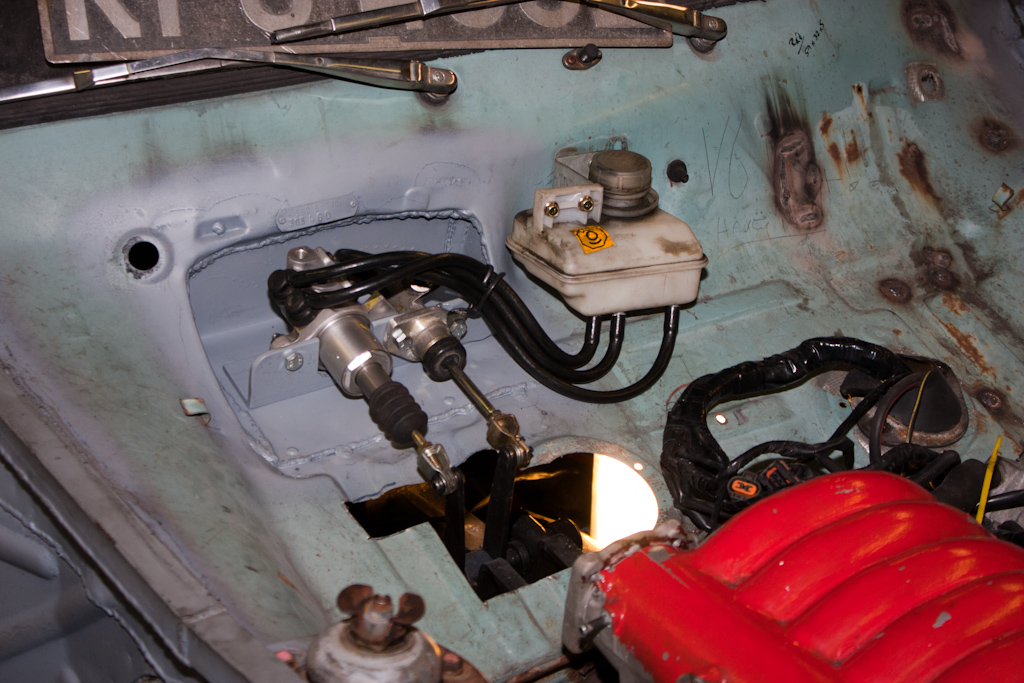
This brought the arms from the pedals to a more upright position, and is acting more directly on the pistons within the cylinders. It also gives more clearance between the throttle body and the pedal arms, which was then improved further, by a few modifications to the inlet plenum.
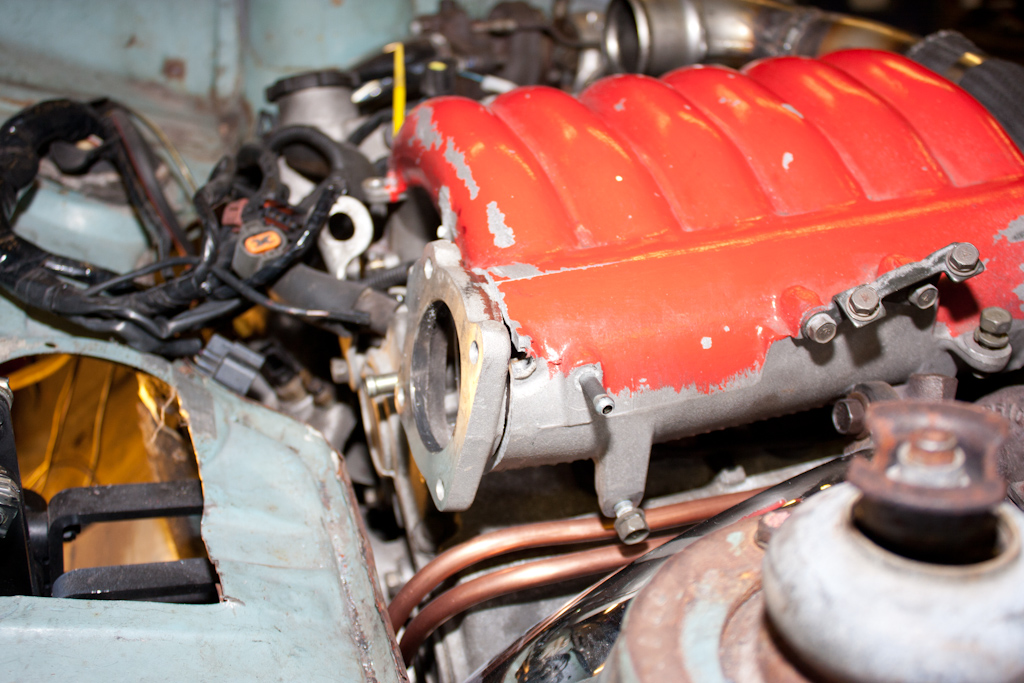
Due to the reorientation of the turbo and the inlet pipework, the plenum required a few brackets removing, and an end chopped off, so that it will sit fully down onto the engine. A small amount was taken from the end where the throttle body is, to angle the throttle body upwards slightly, again giving more clearance for the intake pipework to fit.
The plenum will be taken to be welded up fully soon.
Some water pipes were also made up on both sides of the engine for cooling of the turbos.

Last edited:
Soldato
- Joined
- 29 Jun 2004
- Posts
- 12,954
Looks fantastic! ") I'm looking forward to the completed car.
I'm looking forward to the completed car.
Out of curiosity, how much engineering calculation goes into your project. Naturally I'm sure you have bits of paper and geometries written down. However, do you go as deep as say, calculating the volume flow rate of the turbochargers as to determine the diameter of the ducts feeding them? Have you calculated the basic stresses and strains that the chassis will undergo? Is there a requirement for post-weld heat treatment?
I'd love to do something like this but fear I'll over think the problem!
I'm looking forward to the completed car.Out of curiosity, how much engineering calculation goes into your project. Naturally I'm sure you have bits of paper and geometries written down. However, do you go as deep as say, calculating the volume flow rate of the turbochargers as to determine the diameter of the ducts feeding them? Have you calculated the basic stresses and strains that the chassis will undergo? Is there a requirement for post-weld heat treatment?
I'd love to do something like this but fear I'll over think the problem!
Ricochet... there are no bits of paper, no calculations, no flow rates etc.
There's a couple of measurements written in permanent marker on the body of the car, I think the most important one at the moment is for the maximum physical dimensions for a coolant radiator...
As I am only at my dad's one in every 4 weekends, both myself and my dad have lots of time to sit and ponder things, and we're often on the phone to each other 2-3 times per week saying to each other "what if we were to do this", "would that work", "how about [insert idea here]". However, a lot of it is just holding a piece up and saying to each other "so, how the **** are we going to make that fit" and then do something.
So far, we've been exceptionally lucky in that many things have just fallen together - for example when marking out the gearbox/engine adapter plates, it meant that the gearbox ended up at a slight angle. However, this then worked out perfectly and meant the minimum further modifications in order to fit the water manifold to the back of the engine. However, if we'd made more precise measurements and diagrams, we'd have ensured that the gearbox didn't have that slight angle to it, and then we'd have had major issues making the water manifold fit, because it would want to right where a couple of bolt holes are!
So... we do think about it a lot, but not to the extent of diagrams and calculations!
(Actually, I've put more calculations and measurements into my current "week day" desk project!!)
Last edited:
Soldato
- Joined
- 18 Oct 2002
- Posts
- 8,381
- Location
- The Land of Roundabouts
I've somehow missed this thread, what an epic build
I dont envy your task of getting all that induction pipework plumbed in
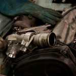
Is that a prelude clock i see?
I dont envy your task of getting all that induction pipework plumbed in
Is that a prelude clock i see?
Soldato
- Joined
- 19 Oct 2002
- Posts
- 18,725
- Location
- Shakespeare’s County
Nice to see it progressing. Dont think that would meet our trustmark of 10mm clearance after engine dynamics though
Will you be able to get the coolant header tank above the turbos?
Will you be able to get the coolant header tank above the turbos?
Yes, there's a lot of intake pipework still to go! I'm hoping someone will soon change the standard ECU to work on a MAP sensor, rather than the standard MAF, as that will massively simplify the pre-turbo stuff! With the MAF I'll need to find somewhere to for the MAF itself and the pipe from it to each turbo.
There is indeed a Prelude clock sitting in the car, whether we'll use it or not I'm not sure, but it looks good in photos!
There's still some minor tweaking to do to the engine bay with a very large hammer when the engine is next out to improve clearance.
I may have space on the passenger side of the bulkhead for a header tank, it's where the original washer bottle is positioned.