Computer Worklog-log [Darkninja462]

Christ almighty, I could never do something like this.

I started this project with only basic engineering skills, but have learnt so much on the way. There have been times where I have been pulling my hair out and thinking I will never be able to finish it, but with the right tools it makes life so much easier and everyday now I am getting closer and closer. I suppose it just goes to show if you want to do something and are determined eventually it will be finished.
 
Update: Cutting 5.25" Drives

I have just uploaded some recent images from my DSLR and realised I have missed out the actual cutting of the 5.25" Bays! So this post will explain just how I did it etc.

You will also see that I have lost the blue wrap to the aluminium and masked everything up, this is just because the blue wrap was falling off and I wanted something more to protect while I was working on it, to reducing any more scratching.

Marking up, probably took about 20 mins to make sure everything was dead square and in the right position:
7655370460_14397883b7.jpg

7655373904_239b2a0a0e.jpg


First cut this does take a long time but is worth it both to preserve the cutting disk and keep a straight edge:
7655376524_73d951e65b.jpg


Hour later and a couple of cups of tea and the hole was cut:
7655379242_e02aee3e7b.jpg


Aluminium plate that was removed and favourite tool the dremel:
7655442694_c57e297f7c.jpg


5.25" Bay waiting to see if it slots in first time:
7655382590_eb43aa52fa.jpg


And remarkably it did fit showing outside and inside view:
7655385292_1af04995f1.jpg

7655387578_f718fc913c.jpg


Finally all bolted in:
7655390026_1f36f12bc4.jpg


Regards
-Ninja
 
Little bit of an update here been aluminium shopping this week so got some of the final bits, currently fitting wire management column which is taking rather a long time per plate (goes through 4 plates.

Will have some snaps soon

-Ninja
 
Little Update: Have nearly finished cutting all the plates now (one more to go) which I would have finished but rained stop play, this should be done by tomorrow. Have been busy planning out some other features while it is raining.

On a side note, I am sure most of you prefer to see hardware rather than my case so have recently purchased new radiators and radiator stands, along with a new Hotswap HDD rack and some cables. Also have some new fans and a controller on its way (Thanks to OcUK Being Cheaper than anywhere else). So pictures of them will be uploaded tomorrow along with all the updates.

Regards
-Ninja
 
This sounds like a pretty epic rig is to be coming...

Will you be using the components in your sig or purchasing new ones? (Will Haswell be an option for around the time of the case being complete?)
 
This sounds like a pretty epic rig is to be coming...

Will you be using the components in your sig or purchasing new ones? (Will Haswell be an option for around the time of the case being complete?)

I wish I could afford an really epic rig, but being Student funds are lacking.

I will primarily be using my current system, however I am spec'ing up a new rig, which will replace my old Mobo+CPU+RAM to something on the lines of a z77 & i7-4770K.

On the lines of it being complete, it depends what you class as complete, I myself want the case to be ready to be powdered by the time I'm back at University so after that should just be final touches and wiring to complete after that. (Don't quote me on this but hopefully a semi-usable case within 6-7weeks).

Regards
-Ninja
 
Wire Management Instillation , I will be hiding all the wires in a central column within the case, this means that they won't be seen until they are used throughout the case, this will use a 2" x 2" box aluminium which allows wires to transfer "invisibly" between the middle section and top section. Cuts will be made along the box section at bespoke points where needed. At the same time I also got the remaining aluminium to make the slider for my motherboard tray and stainless angle for the corners.

The following image shows some of the aluminium and also my little helper that always seems to run off with things I need:
7773718172_dbd58c626e_z.jpg


This image shows the 2" x 2" box section installed using M5 bolts directly to the frame.
7773728158_f61504a325_z.jpg


I then started the long process of cutting each individual sheet so that the column can pass through, this has now been done.

The following images show the column in place with the temporary motherboard sliding rail, how the column passes through the top section and the middle section.
7774954706_30a781e00b_z.jpg

7774961366_06f2e900f4.jpg

7774968632_7ee98a1f12_z.jpg


On the that note it was last week while I was away that some goodies arrived such as a Hot-swap HDD cage, new radiators & stands and some cables.

Regards
-Ninja
 
Here are a few images of some things that will be going into this build soon/later on.

Silverstone Hot-swap HDD cage:
7773735602_d9534263b2.jpg

Unfortunately I don't think I will be able to use the Front fan directly but will use it somewhere love the touch contacts it has.
So I will be using this part of the unit in the top section of the case:
7774514362_b1d1c6dd7c.jpg

Silverstone Screws for the vibration absorbing cages:
7774531528_d9a15233b6.jpg


BitFenix pre-braided extension cables:
7774522926_cd0871b9f4.jpg


XSPC Universal Rad Stands (x2):
7774540128_f72b6dfef0.jpg


XSPC EX480 and XSPC EX360 radiators:
7774548448_9a38d0d370.jpg

7774564258_660ef41b8e.jpg

7774583206_461d9990f1.jpg

7774592576_785f9c36a5.jpg

7774615124_0a2a5b7ffa.jpg


That's all for now, got some more stuff arriving this week, will update with today's work either a bit later or tomorrow.

Regards
-Ninja
 
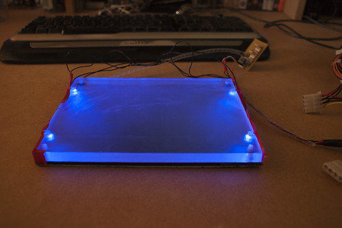
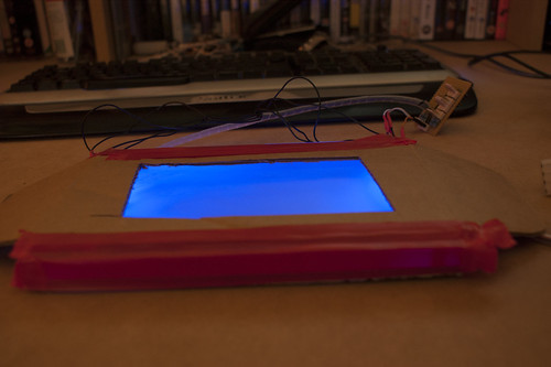
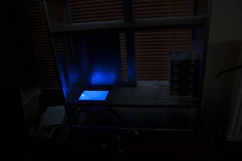
In this post I will show some pictures of more new hardware, a long with a prototype light box I'm trying to make this uses 10mm Frosted Acrylic currently with a 5mm gloss acrylic underneath to bounce the light upwards, using 4 blue 5000cmd LED's placed in each corner. I will be looking to get some mirror acrylic and see what sort of effect that creates but here is the gloss black for now.

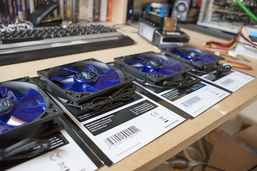
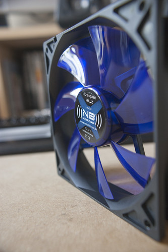
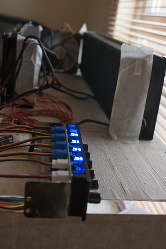
New hardware, got myself some Noiseblocker XL2 fans for the radiators (Might get some more for general case fans later on:
7781225592_992520d455.jpg

Singular Shot of fan:
7781238082_f4464fddd7.jpg

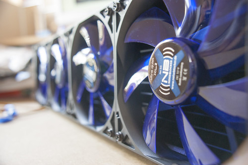
All four attached to the 480:
7781244990_fa2f288718.jpg


And staying in control with Zalaman MFC1-Plus:
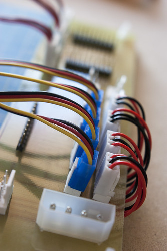
http://farm8.staticflickr.com/7114/7781231892_359d814645.jpg

As for the prototype lightbox

The setup:
7787568662_1fac6251ef.jpg


How it looks from shallow angle:
7787572624_9de0f62cbe.jpg

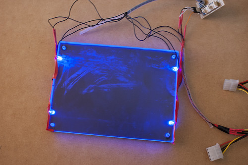
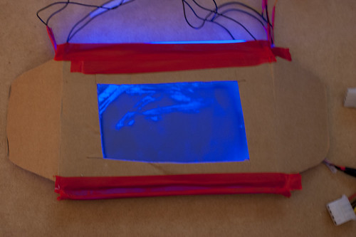
How it looks from above notice the more perpendicular you go the less light is viewable:
7787576916_05e444e4b5.jpg

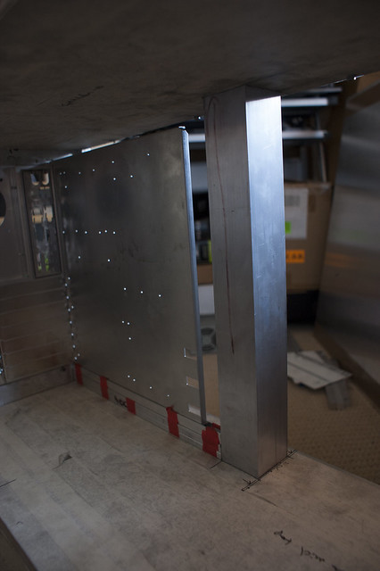
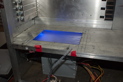
With a cardboard shroud around, this is because it will be attached to the panels of the case (cardboard = aluminium sheet):
7787581770_03a0cc39eb.jpg

7787588128_4e63b614c0.jpg


Please note that this was a spare piece of acrylic due to the imperfections in the face which you can see from the above pictures, as always you can view the rest of the images over on my flickr (Link Here.) and if you have any questions please don't hesitate to ask.

Regards
-Ninja
 
Today's update, after completing the lightbox prototype, I set about cutting the holes in the top of the bottom mid-plate so that the light is case upon the motherboard, so after a 2 hour cutting session, I managed to mount two other pieces of acrylic and some cable management holes.

I also finished mounting my radiators to the bottom of the case, and put everything together to see how the lightbox would case on the rest of the case.

Setting up prototype lightbox, my testing PSU and LED' splitter:
7790634698_de3389f7ed.jpg

Lights on Lightbox on:
7790642970_02945554ab.jpg

Lights off Lightbox on:
7790649844_870c581181.jpg


As you can see even with the black acrylic as a reflector, it gives a very good cast so I think I will keep it for now, also looking down it will match the case when it gets powdered.

So as for the rest of the setup with the actually pieces of acrylic bolted in place:
7790626100_84bea29f02.jpg

7790612252_3c5f34c0a9.jpg


Regards
-Ninja
 
Today's work consisted of entirely cable management in all ~4 hours of it, I had to modify the existing 2" x 2" square tube, so that between the mid-plates wires could pass through it.

I then wired up the 3x 3-Pin Fan Channels which passed between the top section to the bottom section, along with the Front Header wires (Power Switch, Reset Switch, Power LED and Activity LED). Also wired in the 2 wires for the Light-boxes. This itself made for case that looked like it had been attacked by Spiderman.

Also spend the afternoon designing a custom Circuit Board for my control panel. Which led me to order all the parts I need for this and a box to hide it all in which should hopefully be here in a few days (Also avoids me breaching any warranty on my fan controller and fans.). The Circuit board is pretty simple for now but leaves room for expansion at a later date.

Here is the overall picture of all the wires in place:
7796830118_4827a6bd9c.jpg

The lightbox LED wires:
7796838392_0a7e2fe452.jpg

All the wires going to the control panel circuit:
7796845500_17927bd1fe.jpg

Copy of the PCB Design the grid shown is 0.1 inch scale to give some perspective.
7796969480_942decf0bf.jpg


Regards
-Ninja
 
Haven't updated on this project for a while, due to fact my first attempt of making the circuit board to be a failure as the tracks didn't come out properly. So had to get some more materials, due to that I went on to constructing the necessary wires for the fans which I have no completed, to be safe it is 2 fans a channel to not exceed the watts per channel. So a quick couple of images of the final setup for testing, I will hopefully be putting together a post/tutorial about going from wire, housing, terminals and pins to a final full wire.

7814457958_8c31d0e1a7.jpg

7814464110_9c1a9fb48d.jpg


Regards
-Ninja
 
Take two of creating a custom PCB was a success so I now have completed this, the following images show steps during the process.

The etched PCB then sanded to remove the protective coating:
7818243498_6632a514f3.jpg

All the components that will be going onto circuit board:
7818267122_1a4205b055.jpg

Dry fitting of components:
7818288730_3b4a2f9fce.jpg


Finally all soldered onto board:
7818297794_12372c9ffd.jpg

7829635534_6004bbee53.jpg

7829639506_db281d5c72.jpg


Lightbox LED's fully constructed:
7829645044_d3ee911b02.jpg

7829653794_c29f2c2ea0.jpg


and finally the PCB with some of the wires attached:
7829663578_9cb89123c8.jpg

7829658776_c2c96d6062.jpg


Later on I will show some pictures of how the fitted lightbox's are at night.
Regards
-Ninja
 
Good news the case is booked into the powder coaters for tomorrow morning, not sure what the lead time for the company but should be basically done once its back.

Regards
-Ninja
 
Back from the Powder

Looks nifty ... I think you should sell that case to me, and build a better one :)

Well if the price is right I might just do that ;)

On another tantalising note just photographed everything that came back from the powder coaters :D

7936028636_da6d54069e_c.jpg

7936032798_798e4d76ae_c.jpg

7936037264_2f380aeae3_c.jpg

7936041010_e6a66499f1_c.jpg

7936045230_968bcbd904_c.jpg

7936048856_550c857f3b_c.jpg

7936053384_36f9a1af52_c.jpg

7936058180_bb5e76ecc9_c.jpg

7936062590_d311153fef_c.jpg

7936067098_5dee3a6876_c.jpg

7936071188_ddf2dfdf1c_c.jpg


So everything is now looking sleak and clean :D, so will just be making finishing touches and taking my main rig apart to swap into this case.

Regards
-Ninja
 
Back
Top Bottom