eXtreme Liquid Cooling - Build Log + Overclocking

Associate
Joined
16 Jan 2010
Posts
15
Way to **** on his camp fire.

No....that's not the intention at all.....

A lot of people are over optimistic wih TEC's unfortunately that over optimism is directly inversely and exponentially proportional to the happiness at the project end which is felt amongst all the readers of the thread and consequently TEC's get a bad name.

If one works within the capabilities of TECs and understands how they work TEC projects ultimately appear successful and people are not so dismissive of the technology.

One thing this project highlights is that throwing more TECs at a project does not necessarily get you lower temps - you need to understand how TECs work and be a bit more canny. In this project each TEC is a standalone single stage TEC. The have their hotsides collectively cooled so they are basically at the same temp, they are powered the same so they have roughly the same Dt so consequently they have the same coldside temp and cooling so once the coolant reaches the temp of the coldside of one of the TECs thats it...in reality there will probably be a small reduction from there because the TECs wont neccessarily be all EXACTLY the same temp and also having a q much higher than the load can trade off a bit more Dt but it is not neccessarily going to be great. So throwing more TECs at a project and just collectively cooling/powering them is not the best way to low temps...

The only reason you throw more TECs at a project and collectively cool/power them is when you are undervolting to get more efficiency then you have to multiply up the TECs to increase the Q otherwise you have no cooling power BUT if do this hotside cooling is the key you must treat hotside cooling as your sole goal otherwise you end up with an efficent system but not with much cooling.
 
Last edited:
Soldato
OP
Joined
19 Oct 2007
Posts
3,246
Location
Suffolk
Zip,

Firstly thank you for your time.. I would rather get it right now than be disappointed later!

So in this instance as per my examples above by throwing more TECs at the problem I am not increasing cooling which I understand but I am increasing efficiency and hence decreasing the load on the hot side cooling, which should allow it to keep closer to ambient and therefore have better performance under load.. if I understand correctly?
 
Soldato
Joined
22 Dec 2008
Posts
10,370
Location
England
I'm not sure you've completely followed what the design idea is here zip, so I'll offer my interpretation of what the OP is aiming at.

If there's a large heat exchanger with a water loop on either side, driven by pelts. The hot side is cooled down to something like 15 degrees over ambient, this will clearly take a considerable amount of radiators, more if there are more peltiers. Each one will hold a given delta, say 25 degrees while moving a given wattage. Work out/estimate/measure what wattage is dumped into the cold loop, use enough pelts and then enough radiators and you will end up with the cold loop at ten degrees under ambient. Standard chiller arrangement is to send the cold loop through processor etc.

What pneumatic has decided to try in addition to this is a single tec on the processor, cooling the hotside with the chilled liquid. I'm not so sure about this personally, and haven't checked the numbers, but say it's getting a delta of 15K at a processor load of 200W, while drawing something awful like 450W in electricity. This is an extra 450W for the cooling loop to deal with, so it'll need some more tecs in the HX (he's got space for another 4 of them over the current 8). It's also going to need more radiators. You're undeniably hitting diminishing returns, as electricity draw and radiators needed for this extra 15 degrees is considerable. But it'll leave the cpu block at 40 below ambient while moving 200W.

So I don't think it's reasonable to state that stacked tecs cannot work. I don't follow/agree with pneumatics calculations, but I think this is going to work excellently. I'm not keen on the single tec on the cpu, as I struggle to believe one by itself can hold a useful delta while coping with 200W. I personally like the idea of a loop with the cpu on the cold side of a HX, graphics cards on the hot side, hot side cooled by a bigger chiller with a hell of a lot of radiators dealing with the output from the bigger chiller.

Credit to the man for going ahead, and for doing so with such speed. It'll be at least a year before I've got something like this running. I believe this project is going to work well.

The tec I think he's planning on using will hold a delta of 30K if the hot side is held at 28C while moving 175W. It needs 18V and 20A to do this. Or it'll do 225W at delta of 20K for the same voltage/current. So it is viable to cool the processor with a single tec, but the electricity cost to do so is not funny.
 
Last edited:
Associate
Joined
16 Jan 2010
Posts
15
Zip,

Firstly thank you for your time.. I would rather get it right now than be disappointed later!

So in this instance as per my examples above by throwing more TECs at the problem I am not increasing cooling which I understand but I am increasing efficiency and hence decreasing the load on the hot side cooling, which should allow it to keep closer to ambient and therefore have better performance under load.. if I understand correctly?

Ahhhh...that's where your problem lies....

efficiency is not really the right word with TECs strictly it is COP - coefficient of performance - a lot of people just call it efficiency but this isn't strictly true.
Coefficient of performance is your cooling power divided by your input power.
Cooling power is your collective Q at your operating point (not qmax ! unless your running vmax.), input power is the individual TECs input power added together, again at the operating point.
Generally you have a COP of 1 or less when powering a TEC to greater than 50% power (this is very rough !!) at full power the COP can be as low as 0.45, meaning you only have a cooling power of 45% of your input power.

COP has nothing to do with decreasing the load on the hotside cooling - it is not efficeincy per se.
 
Associate
Joined
16 Jan 2010
Posts
21
I'm not sure you've completely followed what the design idea is here zip, so I'll offer my interpretation of what the OP is aiming at.

If there's a large heat exchanger with a water loop on either side, driven by pelts. The hot side is cooled down to something like 15 degrees over ambient, this will clearly take a considerable amount of radiators, more if there are more peltiers. Each one will hold a given delta, say 25 degrees while moving a given wattage. Work out/estimate/measure what wattage is dumped into the cold loop, use enough pelts and then enough radiators and you will end up with the cold loop at ten degrees under ambient. Standard chiller arrangement is to send the cold loop through processor etc.

What pneumatic has decided to try in addition to this is a single tec on the processor, cooling the hotside with the chilled liquid. I'm not so sure about this personally, and haven't checked the numbers, but say it's getting a delta of 15K at a processor load of 200W, while drawing something awful like 450W in electricity. This is an extra 450W for the cooling loop to deal with, so it'll need some more tecs in the HX (he's got space for another 4 of them over the current 8). It's also going to need more radiators. You're undeniably hitting diminishing returns, as electricity draw and radiators needed for this extra 15 degrees is considerable. But it'll leave the cpu block at 40 below ambient while moving 200W.

So I don't think it's reasonable to state that stacked tecs cannot work. I don't follow/agree with pneumatics calculations, but I think this is going to work excellently. I'm not keen on the single tec on the cpu, as I struggle to believe one by itself can hold a useful delta while coping with 200W. I personally like the idea of a loop with the cpu on the cold side of a HX, graphics cards on the hot side, hot side cooled by a bigger chiller with a hell of a lot of radiators dealing with the output from the bigger chiller.

Credit to the man for going ahead, and for doing so with such speed. It'll be at least a year before I've got something like this running. I believe this project is going to work well.

The tec I think he's planning on using will hold a delta of 30K if the hot side is held at 28C while moving 175W. It needs 18V and 20A to do this. Or it'll do 225W at delta of 20K for the same voltage/current. So it is viable to cool the processor with a single tec, but the electricity cost to do so is not funny.


heres my over clocked Q6600 being cooled by one 62mm TEC if thats any help

http://www.overclock.net/7775720-post3.html
 
Associate
Joined
16 Jan 2010
Posts
21
Ultrasonic,

Thank you for your input its much appreciated..

The calculations were based on an increasing input power to the units as the heat load was increased, more than anything to be as 'power efficient as possible' (I.e the QMAX of the system @ 125 TDP is a lot less than at 300 TDP). Thats why the graph is showing a constant-ish delta, other than towards the upper TDP's where the hotside temperatures on the chilled liquid loop start to increase as the water loop beings to have 'issues' dispersing the heat, is this incorrect? Assuming that the water loop can keep the hotside of the chilled liquid loop at a constant-ish temperature then I should maintain the same delta at an increasing TDP if I am proportionally increasing the QMAX? That was my understanding?

Edit: To make sense!


ok so your increasing the input power to the TEC as you increase the load it's cooling to keep the delta the same.

It understand that graph better now .. however what i said is still true
your graph is impossible. on the far right of your graph you have the 360 watt TEC moving 300 watts to a delta which is unattainable. espcailly if the TEC is under volted or the hot side of the TEC is below 300K

Presuming that the TEC in question is able to move 300 watts at your input power and hot side temp then the hot and cold lines on your graph must intersect on the far right of your graph

Because "Q" is a measure of the amount of heat (in watts)that can be moved from the cold side of the tec to the hot side of the TEC while a achieving a delta DELTA of 0 ( to a delta of 0 is the important part )

SO if you have 300 watts of "Q" cooling from a TEC and you apply 300 watts of heat to it the resulting delta is 0 ....So in your graph it is not possible to keep the delta the same as you increase the load even if you increase input power. because you dont have enough Q to begin with.


edit
Id Love to post a pic of how it should look but this forum wont let me attach pic .. which a real pain
 
Last edited:
Soldato
Joined
22 Dec 2008
Posts
10,370
Location
England
Based on the varying gradient of his first graph I think they show a varying number of pelts in use. On the far right more of them are switched on than near the left. I could be wrong here though.

I'm intrigued by this Ultrasonic. It's starting to look like a single 62mm tec can deal with a modern overclocked processor, yet common knowledge appeared to be that this is not the case when I looked into it a while ago.

Are you still making and shipping the combined tec/water blocks? At what sort of cost? I'm nothing like good enough with a mill to make a cpu block out of copper but may wish to buy one.

At 12V, the biggest tec I can find will break even at 275W. So that's maintaining a delta of zero, and if heat load goes over 275 it'll die and kill the cpu. That's not too bad for a safety margin. If moving just over 200W it'll offer a delta of 10k. Pulls 160W to do so, which just wouldn't bother an atx psu. I think the i7 920 pulls about 200W and it's reasonable to assume it wastes all of it as heat. Ultrasonic, I think your waterblock will deal with a 920. Hell of a lot easier to insulate since the top of the block is hot rather than cold. I like your design.
 
Last edited:
Associate
Joined
24 Feb 2009
Posts
1,720
Location
Teesside
Not looked at this thread for a while! Looks like the build is coming along nicely :) Bit too much maths in between build updates though :p Guess its got to be done on a build like this though
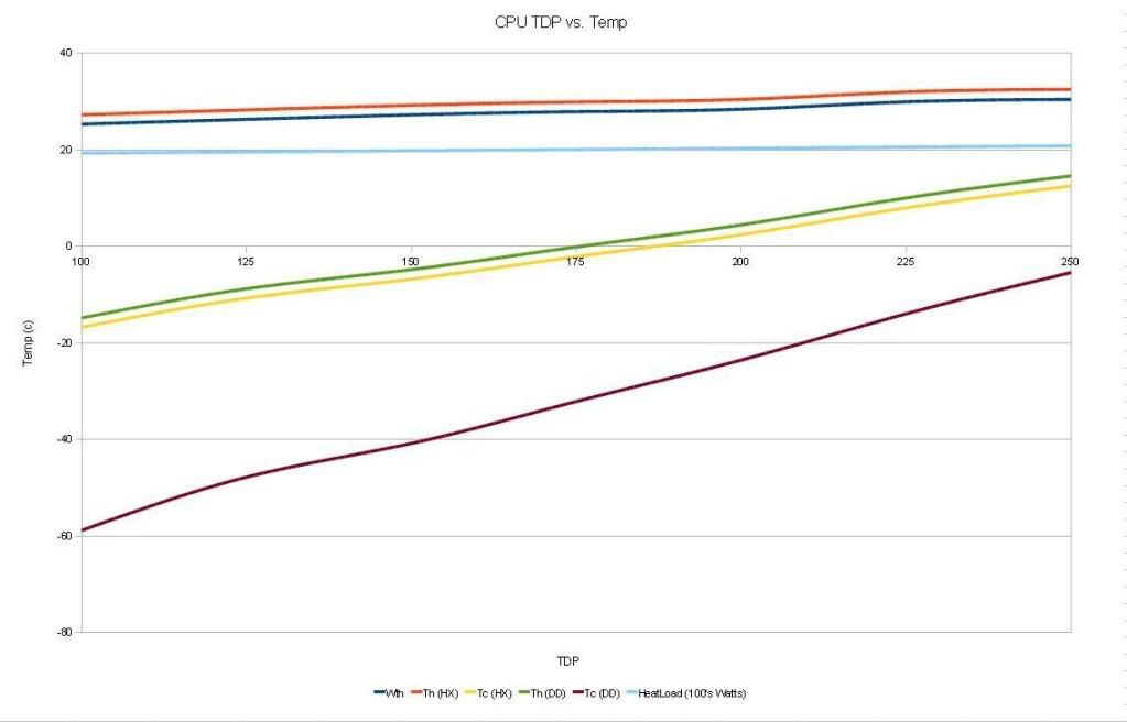
 
Associate
Joined
16 Jan 2010
Posts
21
Based on the varying gradient of his first graph I think they show a varying number of pelts in use. On the far right more of them are switched on than near the left. I could be wrong here though.

I'm intrigued by this Ultrasonic. It's starting to look like a single 62mm tec can deal with a modern overclocked processor, yet common knowledge appeared to be that this is not the case when I looked into it a while ago.

Are you still making and shipping the combined tec/water blocks? At what sort of cost? I'm nothing like good enough with a mill to make a cpu block out of copper but may wish to buy one.

At 12V, the biggest tec I can find will break even at 275W. So that's maintaining a delta of zero, and if heat load goes over 275 it'll die and kill the cpu. That's not too bad for a safety margin. If moving just over 200W it'll offer a delta of 10k. Pulls 160W to do so, which just wouldn't bother an atx psu. I think the i7 920 pulls about 200W and it's reasonable to assume it wastes all of it as heat. Ultrasonic, I think your waterblock will deal with a 920. Hell of a lot easier to insulate since the top of the block is hot rather than cold. I like your design.


On his graph he is using a single TEC ( my block ) to cool the load of 300 watts . which is then in turn being cooled by an array of TEC's

im primarily talking about the single TEC block in his graph .. though the affects im talking about also effect the array of TEC's but to a lesser degree


More info here

At this stage i recommend people use the TEC frozen cpu sells . event hough it's not a 437, cos i use this one myself

http://www.overclock.net/cooling-products/618663-62mm-tec-water-block.html#post8206658

People struggle to get TEC's to work these days because people dont fully understand how they work, and therefore are unable to implement them correctly.

IE 99.9% of the people want to TEC on the cheap .. if you do that you are doomed from the start ..

You can't / dont want to run a TEC like mine off a normal PSU cos you need more volts ..
 
Associate
Joined
16 Jan 2010
Posts
15
Pneumonic....here is my 2 pennies for you....

Let me just say your project will work....

I understand your design restrictions...

your heat exchangers - I appreciate you don't want to build anything so you got some commercial ones. The problem I see is that TEC give off heat over their whole surface and as good as those heat exchangers are, i am sure, it is difficult to arrange TECs on it for best performance. I am hoping you can mount the TECs direct on the tubes but I doubt itI don't think it would be flat enough but even if you could a 40mm TEC on a 15mm pipe......

your hotside cooling - I know you have 2 fans on two passive coolers but if it was me I would think a big rad box with with some decent fans. really push the hotside cooling. But i assume you don't want the noise.

Your TECs - are perhaps not quite big enough for "hard core" undervolting i don't think you could get away with less than 8 but also I don't think increasing the the no. of TECs to increase the Q will help. it is Dt you need or some very good cooling on the hotsides.

Your power - Using a PC PSU is never a good idea for one you are restricted to 12v generally, as you were. So you had to undervolt to 50% and it is a bit of a half way house if you were planning for COP you have only just got over 1 another 5-10% would have got you at least 2, but of course with this size TEC your Q might of gone down too much. A decent variable voltage PSU is always useful when undervolting, I can't stress it enough. Once you get near the 40% power area COP can rise dramatically with just a small increase (edited - sorry read small decrease.) but remember of course at power less than 25-30% COP drops like a stone.

BUT despite all this and anything else I can think of with more time your project WILL WORK so long as you aim at a reasonable target and understand the limitations of your setup/TECs.

The idea is sound... cooling coolant to cool a direct die cooled CPU. This works, to a point, because you are cooling the hotside with chilled coolant ( subzero preferable not 5ºC) and you should be using a TEC at high power on your CPU to get the high Dt.

Direct die cooling does have problems due to the ever increasing TDP's there are possibilities to use 2 high power but physically smaller TECs such as 50mm side by side it is possibly tight stuck between the ram and the back of the sockets but not impossible. This increases the Q to a useful level.
But you will have to get someone to make it for you.

The problem with many TEC projects is people do them in the wrong order.... you need to get your cooling requirements, get the right size TECs and power then sort your hotside cooling then fit this into your project.
It is wrong to set your project up first then try to shoehorn the TECs in after.
 
Last edited:
Soldato
Joined
22 Dec 2008
Posts
10,370
Location
England
I don't think he's planning on dealing with the heat load just using the two reservoir radiators. At least I certainly hope not.

I think I've got a clear understanding of how these things work. Certainly they don't seem to be very complicated and the graphs are trivial. Predicting performance curves based on rated specs is harder, and I'm failing to find out how hot side temperatures affect cop at given voltage & current. If the processor is drawing less than 200W it does look like a 62mm pelt can cope, and the move to 32nm in the near future may mean it'll cope with the next generation too.

I know that the general consensus is that atx power supplies are a bad idea for peltiers, for the joint reasons of 12V being relatively low and atx power supplies tending to die under particularly heavy load. However I also know that 12/6V is conveniently available. I've got a psu here which is good for 60A on the single 12V rail during 24/7 operation and has two peg cables free, so as long as I'm pulling less than 25A at 12V the psu isn't going to mind. Seems a waste to get a meanwell if I can make do on 12V.

Based on this datasheet, reading at 12V I'm predicting 14A draw and 225W moved at a delta of 10, system failure at 275W. I think ten degrees below water temp would be worthwhile, but would need to estimate loses across the junctions and through the copper before making an informed decision on whether to ask you to make another one or not.

Any chance of you sharing a model of the combined waterblock/cold plate for me to examine? FEA is beyond me but I should be able to estimate heat loss at the copper-copper, copper-ceramic, ceramic-copper boundaries at least. Hard to guess if its viable without calculation, I have a nasty suspicion that it would be awesome on an e8400 but not worthwhile on a 920.

edit: actually fun though a model would be, I think the dimensions you've posted are comprehensive enough. I assumed you'd milled a 62mm square indent out of the tec facing sides but I'm no longer so sure, are they flat on the side adjacent to the peltier?
 
Last edited:
Soldato
OP
Joined
19 Oct 2007
Posts
3,246
Location
Suffolk
Zipo,

Just to give you a little more info

Let me just say your project will work....

I understand your design restrictions...

your heat exchangers - I appreciate you don't want to build anything so you got some commercial ones. The problem I see is that TEC give off heat over their whole surface and as good as those heat exchangers are, i am sure, it is difficult to arrange TECs on it for best performance. I am hoping you can mount the TECs direct on the tubes but I doubt itI don't think it would be flat enough but even if you could a 40mm TEC on a 15mm pipe......


I understand the heat exchangers aren't ideal however is a function of £ / performance here and hopefully the two copper plates between the exchangers / TEC's will help even out the hotside temps.

your hotside cooling - I know you have 2 fans on two passive coolers but if it was me I would think a big rad box with with some decent fans. really push the hotside cooling. But i assume you don't want the noise.

Your TECs - are perhaps not quite big enough for "hard core" undervolting i don't think you could get away with less than 8 but also I don't think increasing the the no. of TECs to increase the Q will help. it is Dt you need or some very good cooling on the hotsides.

It's a bit of a long and muddled log so far :) but there are also four Thermochill PA120.2 rads in the cooling loop, which should dump enough heat.. I have a couple of spare PA120.3 I can rear mount externally on the case as well if needs be.. hot side cooling I don't think will be an issue

Your power - Using a PC PSU is never a good idea for one you are restricted to 12v generally, as you were. So you had to undervolt to 50% and it is a bit of a half way house if you were planning for COP you have only just got over 1 another 5-10% would have got you at least 2, but of course with this size TEC your Q might of gone down too much. A decent variable voltage PSU is always useful when undervolting, I can't stress it enough. Once you get near the 40% power area COP can rise dramatically with just a small increase but remember of course at power less than 25-30% COP drops like a stone.

I have a 24v PSU I was going to use on the 62mm TEC, I could invest in another, variable voltage control is to be provided via PWM units.

BUT despite all this and anything else I can think of with more time your project WILL WORK so long as you aim at a reasonable target and understand the limitations of your setup/TECs.

The idea is sound... cooling coolant to cool a direct die cooled CPU. This works, to a point, because you are cooling the hotside with chilled coolant ( subzero preferable not 5ºC) and you should be using a TEC at high power on your CPU to get the high Dt.

Direct die cooling does have problems due to the ever increasing TDP's there are possibilities to use 2 high power but physically smaller TECs such as 50mm side by side it is possibly tight stuck between the ram and the back of the sockets but not impossible. This increases the Q to a useful level.
But you will have to get someone to make it for you.

The problem with many TEC projects is people do them in the wrong order.... you need to get your cooling requirements, get the right size TECs and power then sort your hotside cooling then fit this into your project.
It is wrong to set your project up first then try to shoehorn the TECs in after.

Again thank you for the input, your constructive criticism is welcome.. and I would value any further input you have as I proceed..

Following your comments I have re-visited my graph (which had a number of flaw previously) and produced this:

TDPvs.jpg


Which is the 62mm 19911 running @ 22AMP's/19v and 12 40mm 12711 (15.2v, 142QMax) running @ 9AMP's/8v.. this gives me similar QMax but greater Dt..

I think if I ran the 40mm 12711 @ 12v I would get a 28k Dt rather than 21k Dt @ 70W / TEC ish (200 TDP CPU Load equivalent, 62mm TEC + CPU Load)

Alternatively if I ran 12 of the 40mm 19911 running @ 11AMP's / 17.5v on an alternative PSU I would see around a 35k Dt @ 70W / TEC ish (200 TDP CPU Load equivalent, 62mm TEC + CPU Load), so around -38c @ 200 Watt TDP... but that dumps another 1400 - 1600 watts into the hot side loop.. as per below

40mm19911-1.jpg

Note: I haven't recalculated the water temp on this as the heat load goes off my chart..
 
Last edited:
Associate
Joined
18 Oct 2002
Posts
791
Location
Brighton UK
I can't link the site because it MIGHT class as a competitor but this

15V 40A SMPS WITH DIGITAL DISPLAY

has variable output voltage of 3-15 V at up to 40 A (if that's big enough;)) and can be had for £95. There is also a 60A model....
I use the 30A model to run two of the "437" W Frozen CPU TECs that Ultrasonic mentioned in parallel at 12 Volts/ 25A

:)
 
Last edited:
Soldato
Joined
22 Dec 2008
Posts
10,370
Location
England
hopefully the two copper plates between the exchangers / TEC's will help even out the hotside temps.

I missed this somewhere along the road. The heat exchangers you're looking at are aluminium blocks with slots milled out and copper pipes pressed in. If you're considering tec - copper sheet - pipe side of HX, I'm pretty certain you'll get better performance by omitting the copper sheet and turning the HX over. I'm not alert enough to work anything out for this though I might give it a bash tomorrow (revising thermofluids at present & tomorrow, good to have real world problems to solve), but this would be a very good thing to test.

^You mean output voltage of 3-15V, right?

Regarding condensation, I assume there's a reason why people don't just use heaters around the socket and behind the motherboard?
 
Last edited:
Associate
Joined
16 Jan 2010
Posts
21
I don't think he's planning on dealing with the heat load just using the two reservoir radiators. At least I certainly hope not.

I think I've got a clear understanding of how these things work. Certainly they don't seem to be very complicated and the graphs are trivial. Predicting performance curves based on rated specs is harder, and I'm failing to find out how hot side temperatures affect cop at given voltage & current. If the processor is drawing less than 200W it does look like a 62mm pelt can cope, and the move to 32nm in the near future may mean it'll cope with the next generation too.

I know that the general consensus is that atx power supplies are a bad idea for peltiers, for the joint reasons of 12V being relatively low and atx power supplies tending to die under particularly heavy load. However I also know that 12/6V is conveniently available. I've got a psu here which is good for 60A on the single 12V rail during 24/7 operation and has two peg cables free, so as long as I'm pulling less than 25A at 12V the psu isn't going to mind. Seems a waste to get a meanwell if I can make do on 12V.

Based on this datasheet, reading at 12V I'm predicting 14A draw and 225W moved at a delta of 10, system failure at 275W. I think ten degrees below water temp would be worthwhile, but would need to estimate loses across the junctions and through the copper before making an informed decision on whether to ask you to make another one or not.

Any chance of you sharing a model of the combined waterblock/cold plate for me to examine? FEA is beyond me but I should be able to estimate heat loss at the copper-copper, copper-ceramic, ceramic-copper boundaries at least. Hard to guess if its viable without calculation, I have a nasty suspicion that it would be awesome on an e8400 but not worthwhile on a 920.

edit: actually fun though a model would be, I think the dimensions you've posted are comprehensive enough. I assumed you'd milled a 62mm square indent out of the tec facing sides but I'm no longer so sure, are they flat on the side adjacent to the peltier?


i have done PLENTY of thermal simulations on my block you can read it here
657 posts and 26,000 veiws

http://www.overclock.net/peltiers-tec/529584-custom-62mm-tec-water-block.html

in any case if it's no good at 12 volts you can buy a higher voltage PSU later if you want
 
Soldato
Joined
22 Dec 2008
Posts
10,370
Location
England
Indeed, I've seen the thread. It's not unreasonable that I'd want to do my own calculations as well. I'm interested in the temperature difference between the cpu ihs and the copper in contact with the water, which I can't see anywhere in that thread. There's a fea analysis of the performance of the waterblock side. Since 12V would be looking at a load delta of 10K this number is pretty significant.

Could you clarify whether the tec facing sides of the copper block is flat, or with a ~65mm square indent to seat the tec? I'll take that as a "no" to letting me see a model of it then.
 
Back
Top Bottom