Not powering up

Associate
Joined
26 Jun 2005
Posts
1,983
Location
Chelmsford
Ok, here's what im putting together for my friend.

[email protected]
Asrock 4CoreDual-SATA2 mobo
Geil 2GB PC25300C4 DDR2
*My old 6800le AGP*
WD RAID edition 160GB HD
Samsung DVD-RW
Antec Sonata III w/500W ATX2.2 PSU

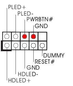
All necessary cables and plugs are in, 2 motherboard cables, cpu fan, pwr,pwr led, reset, hd led etc.

Any ideas why it won't power at all?
 
yes it does matter the motherboard has 2 pins for the power

panel.jpg


just downloaded the manual as i couldnt not get a decent pic if the mobo

i have put red dots for the 2 pins needed for the power switch
 
Last edited:
fenderbass86 yes it's important. Double check all the pins to make sure you're not plugged any more in the wrong places.
 
Ok, so the PWR switch has to cover two pins, however, I only have one available once the PWR LED is covered. It takes up 3 pins alone. Can that be right? Or should I return the motherboard for a good one?
 
I'd plug in the PWR switch first and then worry about having enough pins for the LED once it was working. (I don't always bother with the LED anyway)
 
NOW AND THEN you get a missmatch with the speaker because it's 3 pins wide but only uses the outer 2.

Can you draw out, or describe all the pins that you have on the motherboard please? I agree with maf718 - get the power switch and the reset switch on there first. Then have a look at the other ones (which are less important). In this day and age who needs a little LED to tell them the PC is on - that's what all the fans are for :-)
 
I used to have an asrock mobo and the pin assignments were exactly the same as cupra drew a few posts above, I think its a pretty standard setup. When I changed my case to an Antec one, the power LED connector was 3 pin with middle one blank, so didn't fit. I just left it off, everything else fitted, its no big deal. If you absolutely have to have the power LED just butcher the connector from the case to give you two single connectors. ;-)
 
The picture above in Cupras post is correct.

power.jpg


PLED+ and PLED- is a 2 pin for the LED, and PWRBTN# and GND is the 2 for the one / off button.

If you have a 3 for the PLED you maybe able to make it into a 2 by moving a pin over. Fiddly to get out, but it's possible one some.
Else just cut it in half, and make 2 seperate singles.
 
Well I moved the pwr switch to cover two pins and left the 3 pin pwr led hanging off a pin. All I got was a whine/squeek noise, just for a half second. Nothing else.

Will it help if I take pictures so you can see the connections?
 
Your picture in this post is wrong.
You also have the reset on the dummy pin!!
GET IT OFF.
I doubt your going to be able to show us anything....if the top rail has 4 pins and the one below has 5 then you don't have anything missing.
Ignore the Power LED one (your 3 pin) it's NOT needed.

Your reset has 2 pins and above that sits the on / off (power button and ground)
The dummy pin is NOT used.

Also note HDLED+ and HDLED- is also 2 pin only and does NOT need to be connected. Its a light only.
 
Last edited:
I meant should I post pictures of the whole build, just incase i've missed something totally obvious.

*edit* - Done what you said about the pins, im still getting that squeek noise. I think i'll send the motheroard back, it's not one i would've chosen for my own computer but i needed one with an AGP slot.
 
Last edited:
if you haven't done so already try just plugging the power switch connection into the motherboard header, and make sure you are looking at it from the right side - they are pretty much standard, but often the manuals aren't 100% clear on which say you should be looking at it.

You should also (normally) be able to see the markings on the motherboard for the header, you don't need to worry which way round you get the switches onto the pins, as long as it's on the correct pair of pins (unlike the LED's it'll work anyway).

The squeek noise could be if you've hooked up the speaker to the wrong pins.
 
Back
Top Bottom