Project:- Liquid Skeleton

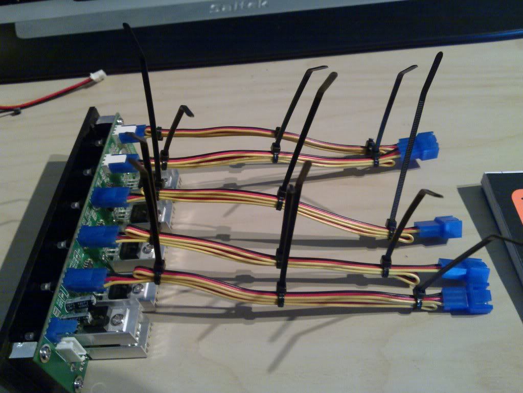
That's a shame and an unfortunate consequence of using voltage regulator driven fan controllers.

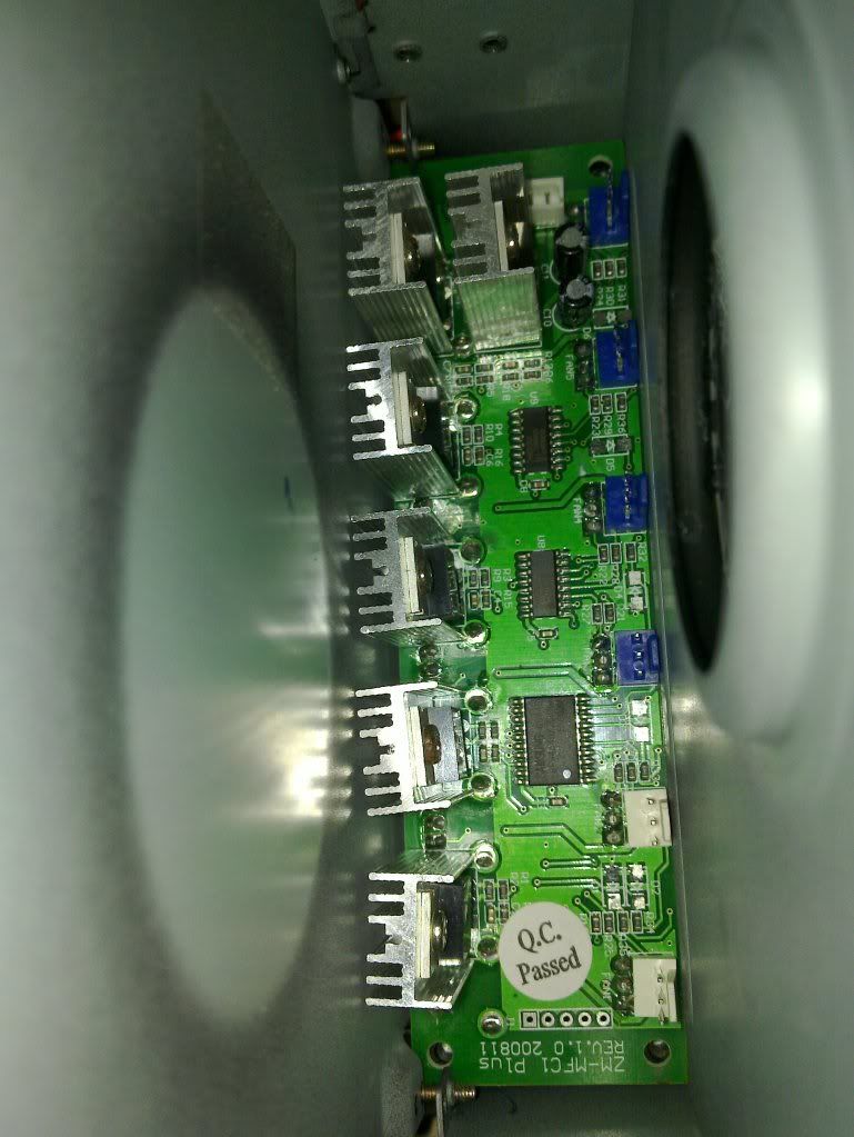
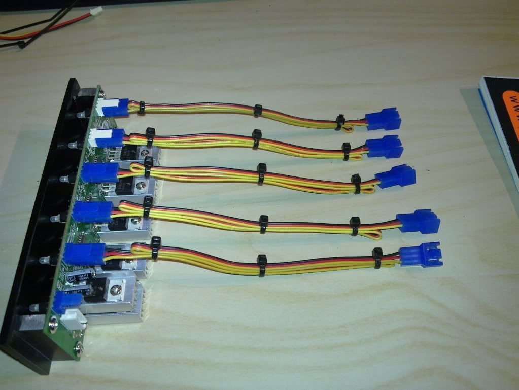
I wonder if you could modify the heatsinks already present to increase their size. You might even be able to incoroprate the case of the drive to increase the area for heat dissipation.

Just thinking out loud.

Edit: actually it may be fine as is because GTs use very little current compared with most fans. Less current drawn means less wattage to be dumped as heat.
 
Last edited:
It was actually our old chum Waynio who identified the potential issue. I'd thought of using the case as part of the sink also, so nice to know I was on the right track.

Not too bothered about having to put a fan in, but would rather not if I don't need to.

May put it underneath so as to keep the look of the top of the box, but a bit of me says chop a hole in the top paint the blades yellow and drop in in there.

So top or bottom? Push or pull. Bearing in mind the box will be open at the rear with regards to pull creating a negative pressure inside.

If I do use a fan I'll probably go for one of the slimline Scythes
 
How many fans are you controlling with it? Are you bunging all rad fans on a single circuit or spreading the load across multiple circuits?

If you are loading 3 or more to one channel then you could upgrade the heatsink for that one only.

I think at most you'll need to dissipate a couple of watts per channel even for 3 GTs running at lower voltage.
 
Last edited:
hi Tealc

each of the 3 fans for the rad will be conected seperately. I will also connect the 2 fans on the corsair ram cooler to it (these are 60mm fans and are already spliced together. Also planning to connect the fan on rhe front of the skelly that cools the hdds.

so what do you reckon?
 
I'd be tempted to suck it and see, as it were. Bung a thermal probe in there when it's in use and see where it goes to. Voltage regulators get pretty warm as they aren't particularly efficient. The Zalman is rated at 0.6A so those heatsinks should be designed to work with that sort of current and judging by the size of them I think they'd be fine. If you were using the full 0.6A then heat might start being an issue.

Even if you dont use the casing as a heatsink it'll act as a way for heat transfer to the outside. Were you still thinking of mounting this on your desk? If the rear is open to the air then heat transfer will occur naturally.

I'm not a big fan of using fans where not necessary as you can probably tell.

If you really want a fan then whichever way will work, ideally youd have the fan blowing directly on the heatsinks but of course you are restricted by the size of the bay and the sinks already taking up a fair bit of room near the controller itself. Having a 80/120mm fan further away pulling air from the unit will evacuate the warmer air and draw fresh from the front. Having it push air inside will work but will create vibration and buffetting as the air is forced into a steel panel.

And don't worry these chips can go mighty hot, up to 120c and be fine. Bit like the voltage regs on graphics cards I guess.

I'm assuming they are voltage regulators rather than mosfets because of the large heatsink. I could be wrong, I only have a very basic understanding of electronics.
 
Last edited:
Cheers Tealc

if your understanding of electronics is basic then by comparison I'm in a cave banging rocks together.

Think I might suck it and see.

If it gets hot it's no major job to pop a fan in afterwards.
 
Got a fair bit done today, but not as much as I'd hoped as Mrs Dubs wanted to go shopping for a cocktail dress for a "do" were off to at the end of November. That and me being full of cold (me and half the country)

Anyway, got to grips with wiring the fan controller. I've shortened all the internal leads and will be attaching them to the rear edge of the controller effectively to make fixed sockets.

20101016_002.jpg


20101016_003.jpg


Test fit of the PCB and face plate into the box. Should be able to pack the small space between the sinks and the box with a thermal coupler to aid heat transfer.

20101016_001.jpg


Also made a Molex extension to give power to the unit. Didn't have the same colour wires, but as long as you remember what colour = what new colour you're ok as it all gets braided anyway.

20101016_004.jpg


20101016_005.jpg


20101016_008.jpg
 
The fan controller is now essentially finished, just got to source some little feet for it. Sockets mounted in rear using the very handy 3m extra strong bond double sided tape. How strong is this stuff? Well if you stick something down with it you'd better be sure you want it there forever as you can't get it off even if you want to.

20101017_006.jpg


20101017_007.jpg


Also braided the cables coming from the pump.

20101017_001.jpg


20101017_005.jpg


Mrs Dubs is getting a bit fed up with the state of the kitchen table now as it's been like this for a few weeks.

20101017_002.jpg
 
Last edited:
I think you'll have to buy Mrs Dubs a new table after all this is all over.

If I were to put rusty G clamps on my wife's kitchen table I'd be sleeping on the sofa for a week. What are you going to use the egg boxes for? This is just like Blue Peter.

Braiding does look nice, so much better than all those loose wires floating about and considering you can't hide anything in the skeleton will be all the more important.

I really like the modular look to the fan controller but I do have one little question. Why have you not bothered with the sixth channel? Did you want to avoid using the channel that can't be attached to the drive casing for heatsinking or is it just you'll only ever need the five channels?

Those fan connectors would look awesome if they were yellow, don't you think?
 
Cheers Tealc

Braiding is a bit of a fetish of mine as you probably know. I find it very therapeutic to just sit and braid wires.

Egg boxes are a bit of a red herring in that they just happened to be on the table. We live very rural and have a chap down the road who keeps chickens so we save our boxes for when we go and get some free rangers.

only 5 channels for 2 reasons. Firstly I only happen to need five, which is fortunate as the second reason is that they only supply 4 direct connections with the other 2 being the sort with a leg off to the mobo fan headers. I happened to have a spare direct from the car boot build which made up the 5 I needed.

Skelly is all in bits now with the arch section removed and all the front connectors off. Beauty of this case though is that I can still use the main base section. Using it now in fact.

Got some good pictures of 2 years worth of dust build up.

Hope to post a few pictures later.

And oh yes the table. I guess the greatest thing a man can have in his life is an understanding wife. (it has to be said taking her to posh "do's" does help her be more understanding though)
 
If I were you I'd use a voltmeter to check if the little heatsinks on the fan controller are at 0V or 12V. The transistors which the sinks are attached to can either be npn or pnp, one of which will have the heatsink at the same potential as the supply. Given that you have them near your metal case you may run the risk of creating a short if they are pnp.
 
If I were you I'd use a voltmeter to check if the little heatsinks on the fan controller are at 0V or 12V. The transistors which the sinks are attached to can either be npn or pnp, one of which will have the heatsink at the same potential as the supply. Given that you have them near your metal case you may run the risk of creating a short if they are pnp.

cheers Bubo

If I had the slightest clue how to use a voltmeter that would probably be a good idea.

Seriouly though, would a manufacturer make something which was essentially live on the heatsink. I know 12z isn't a lot but it's enough to start a fire.

Little bit worried now!!!
 
I suppose you could always read the chip number off the trannies and use google to see which type they are.

Plug in the unit to your 12v source, grab a multimeter, set it to Volts and place one probe on the heatsink and another on a ground wire, this can be any of the black wire from the leads you have already attached as they should all be connected toa common ground.

Haven't got a multimeter? Grab one of your spare LEDs, wrap the 470 ohm resistor around the anode leg, touch the free end of the resistor to the heatsink and the cathode of the LED to the ground connection. If it's carrying a charge the LED should light up. You might want to check the unit is actually live by shorting the red and black wires with the LED.

I also doubt that they would be live heatsinks, those sinks would be treacherously close to the chassis of the case
 
On a closer look at your pics it looks as though you've put the fan controller shroud back on rather than leaving it bare. Took me a while to interpret that last pic. You will probably be ok in that case cos they wouldn't have designed the controller with sinks which touch its own metal case which weren't the npn type. It is possible for some controllers to use pnp though with a suitably designed shroud to be clear of them, so it pays to be aware of the issue if you are planning on removing the shrouds of fan controllers for whatever reason.
 
If by the shroud you mean the black case, then it's not anything that came with the fan controller, its a box i've made to house it from an old Optical drive. So I guess the concern is still there.

I'm going to see if I can bottow a multimeter and see if it's live or not.

Should have a few more pics up of Sundays activity later tonight.
 
I've taken the arch section off of the Skelly in order to prepare for the installation of the CPU block and to enable me to access some of the other fans in the system to braid them and link to the new fan controller.

It just happens to be exactly a year since I finished the original Skeleton build so what does a year of dust look like on this case??? I deliberately haven't gone near it with anything to remove dust before now, wanting to see what the build up would be, bearing in mind that we've had builders in for 3 months knocking walls down and plastering and sawing and drilling and the like

So what does it look like.... Pretty much the same as any case really.

The PCB is pretty good, as is the GPU as they are directly under the big top fan.

20101018_012.jpg


20101018_013.jpg


Dust has gathered in "dead areas " as it would in any case, but was particularly bad behind the RAM cooler fans and the HDD fans.

20101017_036.jpg


20101017_035.jpg


Fortunately I've found this great stuff that is excellent for getting rid of dust, It molds into all the nooks and crannies, doesn't leave a residue and does not generate static. You just dab it on and it picks up the dust, fold it over and dab it on again and repeat etc. it also feels really disgusting, but in a Goooood way!!!! The feel reminds me a bit of silly putty.

20101017_030.jpg


20101017_031.jpg


20101017_032.jpg


RAM de dusted 9the white you can see is from the flash.

20101017_042.jpg


20101018_015.jpg


All is fine, de dusted and working well.

Please excuse the wall paper. I took this picture while my wife was logged in to her desktop, so it's showing her wall paper. I'll have a word with her and make sure it doesn't happen again.


20101017_027.jpg
 
Is that Mrs Dubs? ;)

I'd be concerned that that silly putty stuff didn't leave bits of itself all over my motherboard's pointy bits but it seems to do the trick quite nicely.
 
ahhhh.....*drooling* over that picture of megan fox on your screen :D

i think its her anyway lol

That is indeed the delightful Miss Fox, and not Mrs Dubs. Although i do have to say I'm very lucky to have Mrs Dubs as she is most definitely out of my league.

She came down the stairs the other day in a little black number with high heels and stockings. She brought me cold beer sat me down and told me to relax. With a wink she said that when she came back she would give me "what she did best".

Brilliant I thought

I Flippin love Shepherd's Pie.


Right back to business

The braiding continues (I did say I had a bit of a thing for it didn't I)

Taking apart and cleaning up the RAM fan and HDD fan ready for re braiding in Black

20101017_028.jpg


20101017_029.jpg


20101017_024.jpg


20101018_003.jpg


20101018_002.jpg


20101018_010.jpg
 
Last edited:
Back
Top Bottom