Project: Silent Overkill

Ok, some sleeving has been done at last.

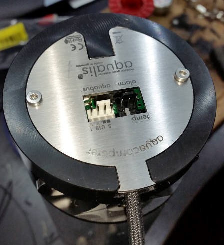
A shiny new USB cable for the Aquaero to the motherboard. Gets rid of the mile and a half of slack but does lose the shielding on the USB cable. So far no problem but it is only about twenty odd centimetres long.


Shortened and sleeved the cables on the front case fans. I did think about buying some overly expensive fans to replace these (I quite like the look of the new Corsair ML140's) but to be honest, these aren't that bad and I've got three of them sitting in my pile-o'-fans :D
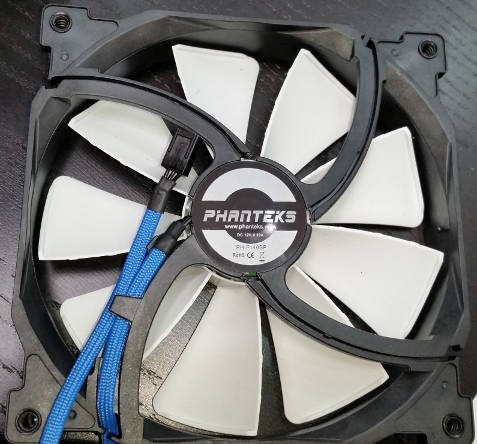


And lastly (for the moment) a three-way fan splitter. Currently I only need two so the third is just blanked off. I'm still debating putting a rear fan in for exhaust but I don't think I really need it; it's only the SSDs, the pumps and the memory that are really dumping any heat inside the case and I can feel some air coming out the back of the case with the front fans on low.
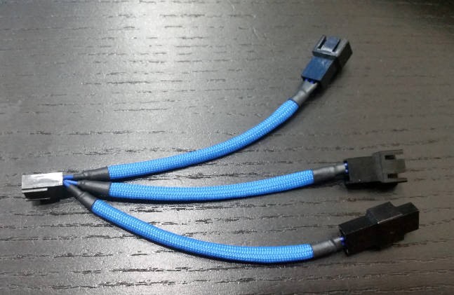
 
Finally made some progress with sleeving. It's been difficult as I've been 'working' at the same time so it means I get a bit done, get called to do something else, lose track of where I was, make mistakes, swear, redo it....you get the picture.

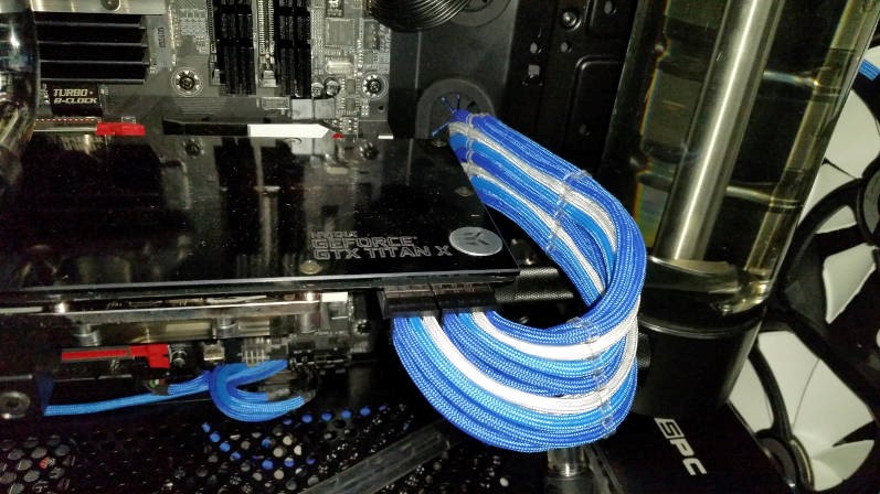
PCI-E power cables for the GPU. These are sleeved individually in paracord to just the other side of the grommet and then bundled in 6mm black Teleios. Just makes it easier to route them spaghetti-side....and also I thought it'd cut me more slack in terms of the length of the wires and the bend :D Combs are E22 14-hole clear stealth combs. Nice and, er, stealthy...but you have to thread them all onto the cables before you put the pin in the shell....or more swearing ensues :D


Started on the Farbwerk too. I bought the connectors for RGB strip lights and have lopped the connector off the end. Sleeved the round cable in black paracord and crimped a pair of female 4-pin fan plugs on the end - I say "fan" but they don't have the offset tab...but I have the matched male sockets so don't care :D

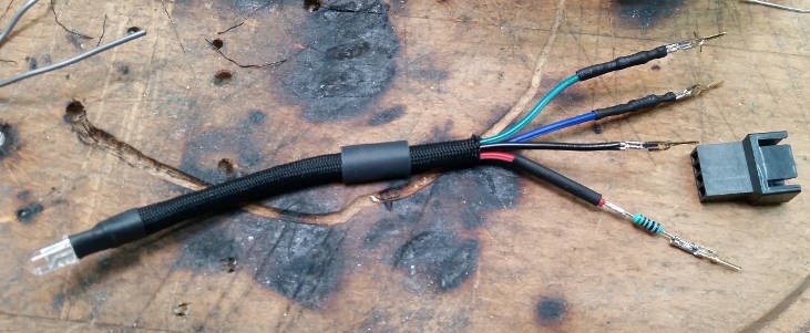
So then, RGB LED with some RGB LED cable soldered onto the pins. Paracord sleeving for that - bad plan, four wires too thick to fit without hours of swearing! Came up with the genius (?) idea of crimping the resistors (510 ohm for red, 430 ohm for each of green and blue) directly into the pins with a dab of solder just for paranoia :D Heatshrink over the lot and shove into the shell - accompanied by swearing because the extra bulk of the heatshrink meant the pins didn't go in easily. Also, for the bright-eyed amongst you, you'll notice that the black pin (common anode) is somewhat shorter than all the rest because I forgot to trim all the rest down by the length of the resistor. I spotted this soon after I took the photo. There was much swearing.


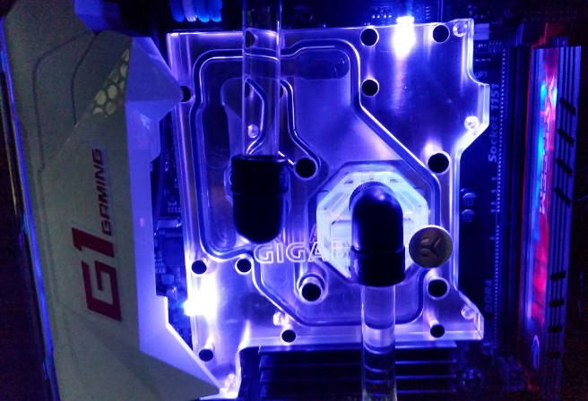
Conveniently I drilled a couple of 5mm holes in the CPU monoblock while I was rebuilding :D Now if I'd remembered to do the same to the GPU block I'd be feeling smug about now! CPU block had no existing holes and GPU has two 3mm holes on the edge nearest the PCI-E slot but all controllable RGB LEDs are 5mm.


Looks good to me :D Had it on colour cycling for a while to play and now have it linked to CPU temp.

Next up is to lop of the ATX plug (they glued the pins into the shell!), crimp new pins on, sleeve each of the wires, develop some new and extra-colourful language and then try to comb it all into submission! :D
 
It sure has. That's a drain and rebuild for some time when I can be ar...bothered.

Depends where you're looking. It's all 550 paracord so nominally it's about 4mm - roughly the same as Teleios. Will not stretch anywhere near as much but is always opaque.
The PCI-E cables are single 18AWG wires in a sleeve. They may not be pulled very tight as they're not anchored at the other end of the cable, just heatshrinked part way down - so they float a bit. The EPS cable is an extension - I needed the extra length (ooh-er Matron!) to route that neatly - so that's properly stretched and anchored both ends.
The USB is something like 24 AWG that I accidentally ordered and already had 2.5mm Dupont connectors on one end but you can get four of them in a sleeve without swearing :D It may be a little fattened to fit though. The black one has four full size cables - I think they're 22 AWG - and was an absolute pain to thread...It's just too big but I was committed. Also it's pulled back as far as I could get it so that it will cover to the pins once they're in.

Also worth noting - if I've not put you to sleep by now - is that the colours are not identical. The light blue is noticeably more capacious and also melts into a more smooshable putty rather than just shriveling up.
 
Last edited:
Patience?! ROFL Have you not spotted the constant colourful language?! :D
I think you're mistaking patience for stubbornness and sheer bloody-mindedness ;)

550 into fan plugs I suspect would be a pain or an impossibility - just heatshrink was too much extra thickness. 550 into PCI-E and EPS wasn't actually that bad. I had problems initially because my crimpers made such a mess of the wings and it made it too big to get in. With the decent crimpers it's not too bad. Just a case of softening the end of the paracord and coaxing it to close in round the end of the pin and set. As long as you get that right, you're golden. It's quite easy to squash it so that it sticks out sideways (like wings) and sets and then it won't fit. You can either reheat and smooth or just snip the sticky-out bits off. The stealth combs were actually less forgiving than the molex shells.
 
Some more work done. Drained the loop and took out the graphics card. Stuck it gently in a vice and heard it crack :rolleyes: no damage it seems, just trying to scare me. Couple of 4.8mm holes for the 5mm LEDs but in different places to the existing 3mm holes as it seemed to light it up better.
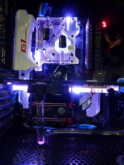
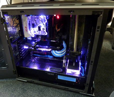
New cable made and sleeved. Resistors hidden mid-cable - one set nicely behind the GPU and one sort of under it...cos I didn't bother to check that there were caps on the motherboard that completely fouled where I'd planned for the cable to run. Still, can't be seen unless you're lying on the floor....and even then it's black heatshrink against a black motherboard.
The result:


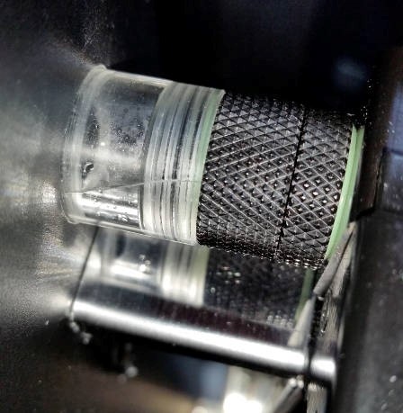
As you can see, I also changed the bottom pipe. Originally I didn't want to bend a pipe as it was going to be temporary. I've since realised that 'temporary' doesn't mean only for a short time :D I also wanted to test out my acrylic thread and transparent o-ring. That worked nicely but the pre-made acrylic link tube had developed quite alarming micro-fractures on the outside and you could actually feel them with your fingernail. It did pass the pressure test but better safe than flooded PSU! :eek:

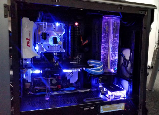
While I was at it, I thought I may as well swap the Aquaero's own single RGB LED in place of the system power led. This is now linked to coolant temp and, like the other blocks, fades from blue to red as it gets warmer...that's why everything is sort of lavender in the pics.
This left the pump block unlit which, although also 'temporary' was annoying....so I through sanity to the wind and wired up another pair of LEDs for that. Would have been fine if I'd not wired one up backwards :eek: :rolleyes:
Now corrected, this is linked to the pump temperature which is read by a stick-on temp sensor on one of the pump's heatsinks. The case fans are also linked to that but stepped so most of the time they're at an almost inaudible 800rpm.


Now, the question you're going to ask is why didn't I light the res while I had it all drained? I know you're going to ask that since I asked myself the very same question as soon as I finished filling it and the lights came on *facepalm*
One for the next drain I think!
 
Beautiful. Love it.

Cheers. Getting there slowly. Still want to replace half the metal with acrylic. Deluding myself that I'll be happy then! :D

Looking good, but going to look even better watching the blocks change with the temperature, both completely in sync & gradually changing the whole look of the case... One complete hammering of the GPU to bump the temps up and all that soldering of LEDs will feel like time well spent :D

Now I've got to ask... Forget to light the reservoir?! :p

At the moment they're not in sync as they're keyed off the temp of the item they're in. Could key them all off coolant temp to sync them up though.

No, honestly. I'd thought about doing it but couldn't because the mounting screws go through the plate that covers the LED holes. Planned to do it at next drain....and failed. It's not a 'guess what surprise I have coming up', it appears I really am just that stupid. Next drain, for sure :D
 
Shiny! I like! :D
Don't mention the RGB word! Already been to two different places today to get heatshrink. 1.5mm fits over the resistors and is small enough to hug the wire when shrunk...but I ran out. Ordered more...and it was missing from the order. Picked up the 1.6mm from stock. 1.6 > 1.5 therefore fine, right? No. The 1.6 is smaller than the 1.5mm...somebody isn't being accurate in their measurements!
Right now I'm trying to get 6 LEDs worth of wiring in a space suitable for 4...at a push! Will get pics up soon...If my sanity holds out! ;)
 
Last edited:
Ok, so why am I constantly whining about how much of a pain it is to wire up these RGB LEDs? I'll try to explain....please leave your sanity by the door :D

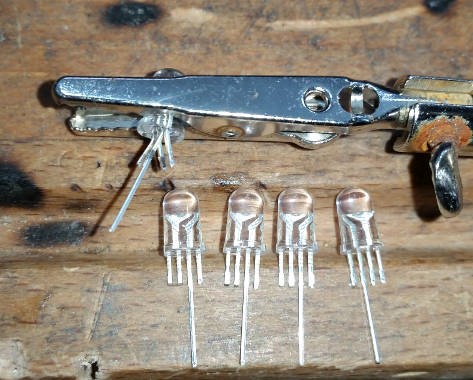
First, you take a bag of 4-pin 5mm RGB LEDs. To work with the Farbwerk - which usually uses RGB LED strips (as opposed to singles) - you need common anode RGB LEDs. This means the 4th pin (or 2nd, if you want to be positional - they're wired R+GB) is a shared positive pin. ALL the RGB LEDs you can buy in this country (I searched quite a few places and found none) are common cathode - the shared pin is negative. So, from China with love, you eventually get a bag of 100....cos I anticipated mistakes :D

You need (for these particular spec LEDs) a 510 Ohm resistor for Red and 430 Ohm resistor for each of Green and Blue. I'd planned to wire them in series but because there is a common pin, you can't. So you need three resistors per LED - you can't share them with LEDs run in parallel off them because you end up with different brightness LEDs....also, that'd be far too easy *sigh*

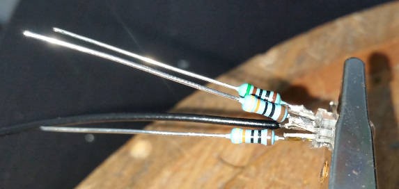
So, I've snipped down the pins to a more manageable length. I've left one longer because I need the whole package to fit down the conveniently deep holes in the bottom of the res so one resistor is going further back to make it slimmer. Pins are then bent alternately forward and back just to make it easier to solder onto them.


Resistors soldered directly onto the LED pins. From the top that's Red (bent up), + (bent down), Green (bent up), Blue (bent down). The resistor for the red is a different value as shown by the different bands - the entire body is actually a different colour but doesn't show up in these high quality pics :D


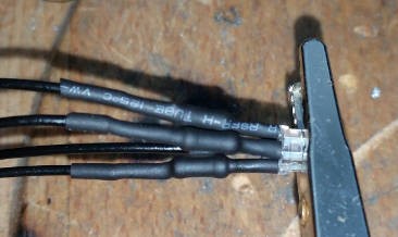
Next solder an excess of wire onto the other side of each resistor - trimming the lead short first. The shared positive had a wire directly onto it as it doesn't need its own resistor. Heatshrink over the top to cover both solder joints and the exposed pin - don't want these shorting out when they're next to impossible to get to. 1.5mm heatshrink from a blue highstreet component shop fits very nicely. 1.6mm from RS, does not :mad:


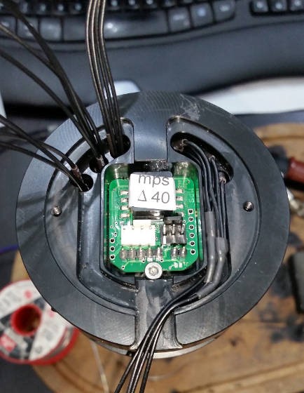
Next, you have to carefully arrange and join all three Red wires, +ve wires, Blue wires and Green wires....I would have made it easier for myself if I'd got wires in each those colours...but clearly I suffer from some form of advanced masochism! The left is before, the right is after.


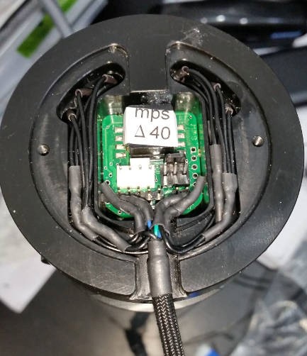
The two sides then had to be joined together and then soldered onto the cable that goes to the Farbwerk. THIS is what stuffed truly means :D I did bend the ends more so they weren't in the way of the pins....just after I took the pic, naturally. There was a fair amount of swearing by this point anyway....especially as I'd found out half way through joining the second bank of three that I'd managed to swap the red and blue channels of one LED and had to carefully cut off the heatshrink and re-solder a longer wire back onto one pin.


And....finished. It's like having to sit on your suitcase to get it shut :D


Currently the res is on what's left of my pressure tester (it threw itself off the desk somehow and now reads 2psi before you start) because I had to open it up and clean off a ring of some sort of residue - like scale or something.
Will get action shots tomorrow once it's all filled :D

Now, you have some idea why my sanity is rapidly failing me ;)
 
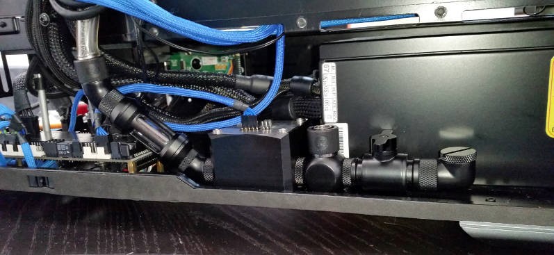
Did a leak test...it passed. Turns out if you remove the stop-plug at the lowest point, coolant forms puddles on your desk *facepalm* In my defense, I had spent considerable effort making sure it was actually empty when I drained it, so I wasn't expecting there to be any there. Pressure testing from a high port instead now. Pics once I've filled it and fired it up. In the meantime, here's the new drain. Didn't want to put it on the outside as I just know it'd get knocked or snapped off. Also a new Barrow strainer as the previous one was showing disturbing cracks in the acrylic (pressure tested ok but...paranoia :D) - this one's quartz glass. Slightly longer than the last, hence the awkward angle of the hose...which was spot-on before. One of these would have worked better but they're not easily available....and I want to fill it NOW :D


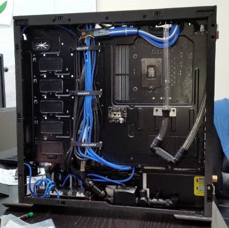
Took the opportunity to take an anti-glamour shot. This is the Spaghetti side. It's reasonably tidy without being too obsessive :D

 
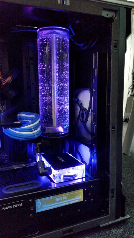
Well, after another round of filtering the pre-used coolant (I'm not replacing £30 of coolant after a couple of months!) I've finally got it filled. Slight moment of panic when the res didn't light up but quickly realised it just wasn't assigned to a controller. Tried to add one and it appears that you can have a max of 4 RGB controllers on an Aquaero. I think I could export sensor values to the Farbwerk and have it control the LEDs but I prefer to keep it centrally controlled so I've just doubled up the outputs on one controller so the case power LED and the res are both controlled off the coolant temp.

Bubbly because it's just been filled but what do you think? :D


Me neither - don't think my sanity could take it. Gotta look on the bright side, at least were it to catch fire, it would be rapidly self-extinguishing....to the tune of about 880ml ;) :D
Shouldn't do though, the soldering isn't bad - tested them all when I pulled on them as I slid the heatshrink over the resistors - and the insulation is fairly obsessive. Once I'd left the lid screwed on overnight, it had pretty much formed to the shape of the channel...which is good as enough things were hacking me off without the wiring jumping out at me as I tried to get the res mounted! The same screws are all that holds the res onto the bracket...that and the weight!
 
That size should be fine even when not braced at the top. Had a 150ml in the previous box and a 100ml in a friend's (150 was out of stock!). Didn't have any issues. The 880 is a little heavier and I was surprised there wasn't a brace at the top. It's fine when its static - and I've wedged a bit of neoprene between the roof and the pressure relief membrane fitting that sticks up a bit....but I wouldn't want to ship it!

Also found that pressure testing it with Dr Drop was really useful. I had to tighten up the screw-cap ends to get a better seal on the O-rings against the glass. At one point it was ok but if you moved the res (like rocked it slightly - or maybe even the weight of the water), it broke the seal and literally farted out the pressure. Probably less of an issue with smaller res's (never had a problem with the 150) but might be worth checking its tight enough.

Your lasered alu looks really promising. Are we going to see what it is yet?
 
To be honest, the worst moment was 2/3 of the way through the second bank of three. For some reason I decided to test them...and found two lit up red on one channel and one lit up red on another channel. I'd got red and blue swapped on one of the three and it took out all the blues. Thought I was going to have to redo the entire bank again for a minute. As it is, it thickened two of the joints (extra wire soldered in) where I really didn't have the space.

Even putting it all back together was a mission. You know when you have those days where everything seems to be on a mission to hack you off? It was one of those. Screws would slip off the Allen key, and then bury themselves in the most awkward place to get them back. You put something down for a second, turn round and it would have disappeared. I think I'd depleted all the colourful language in the area by the time I'd got it all back in!
 
DISASTER!! :eek: (that's not the term I want to exclaim...but this one isn't contrary to the rules!)

Had played a bit of State of Decay and then was dealing with some email. Odd gurgling noise. Had a look and the res was just about empty! Turns out the only pieces of cast acrylic left (other than the blocks) had failed. I'd seen crazing on the Barrow filter and the Barrow 60mm link tube previously used as a riser to the GPU. They pressure tested ok but given that you could feel the fractures with your fingernail I replaced them anyway. The only ones left are the links to the rad and they'd looked fine...Nope!
Top one has split end to end but on the bottom surface where you couldn't see it. Didn't need to bother putting in a drain after all! :rolleyes:

Carpet is soaked (res is 880ml - luckily the leak was the top rad link or I'd have been in line for 2.5 litres. Only plus is that as it leaked externally (external rad FTW! :p) it didn't soak everything inside. Also, thanks to the Vax, I got the spill halted before it filled either the floor box (mains power and networking!) or the UPS!

So currently I'm thinking to replace the acrylic rad links with metal fittings. Not as pretty...but not likely to split either!
 
I'm not honestly sure how fast as for some reason the fill level registered 100% the whole time....which is something I'll be looking at when refilling it! I only noticed when I heard the churning as the res was nearly empty. The pros and cons of black office carpet....it doesn't show the wet.

Took me a little while to work out where it had leaked from too! In that pic, the tube has been rotated but normally that split was pointing straight down so you couldn't see anything - even though it's clear.

As you say, good that I got away without soaking everything at least. Not that keen to test the non-conductiveness to that degree! Turns out there's at least some wisdom in mounting the rad on the outside :D ;)
 
I think that the Barrow supplier is having a long weekend - which is fair play...but why do these things always happen to coincide with a weekend?!
Going to see if I can knock something up for the weekend.
 
So, where are we now? Well, parts should turn up on Wednesday to replace the acrylic links to the rad. Good job I had a play around as just straight replacing 20mm tube with 20mm worth of extenders didn't fit!

For now, I've cobbled it together with a variety of spare parts: a Barrow 10.5mm F-F extender, an EK 8mm M-F extender and a Barrow 15mm M-M rotary. Spurs were suitably sharpened before assembly *jingle* ;) The lower link is still as it was....and that doesn't make me at all nervous *cough* Still, I need to get some gaming in at times over the weekend.

Three things I did discover while reassembling:
  • If you run the pumps to before replacing the cap you left off on the rad to allow the air out, it WILL spray coolant over your keyboard! Seriously, who let me near the wet stuff?! Not sure I'm even cut out for air-cooling sometimes!
  • The fill level sensor on my res is stuck. It's differential pressure based so the only thing I can assume is a blockage or it's suddenly developed knackeredness. It did work while I was filling it last time after the LEDs though. Must have stopped some time afterwards. Will strip it down when I get the parts in and see if it wants to play. May have to swap out the module from the 150ml I've got.
  • My Aquaero is most likely going to need replacing. The speaker was a bit dodgy before....but filling it full of coolant means that at best, it can click slightly. It also seems to stop responding to the screen buttons after a while. I don't think it's the cable - although I will shorten it and do better crimps now I have the tools. I suspect that the three-legged capacitor on the end that went crack when I put the heatsink on may be to blame - it stuck up a bit too far. I think it may be destined to become the media unit controller I kept trying to persuade myself I needed.

Well, one screen up and running but enough for gaming. Don't trust it on the floor for the moment and need to give the carpet time to dry!....but she ain't dead yet :D
 
Back
Top Bottom