Random 3D printing chatter

Soldato
OP
Joined
4 Jun 2007
Posts
2,623
Location
Watford, UK
Not a problem, just wasn't sure if I was more clueless than I was aware! :D
Looks good by the way.

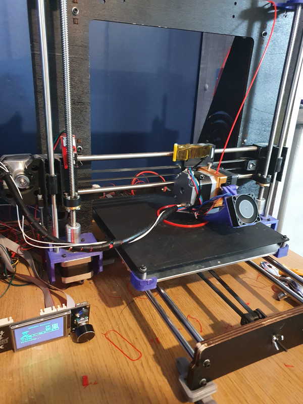
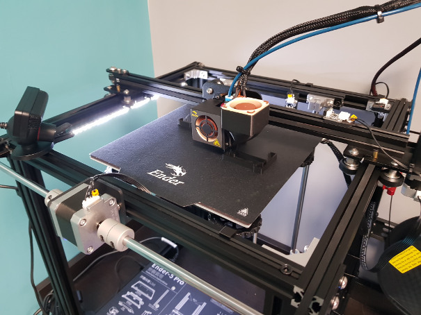
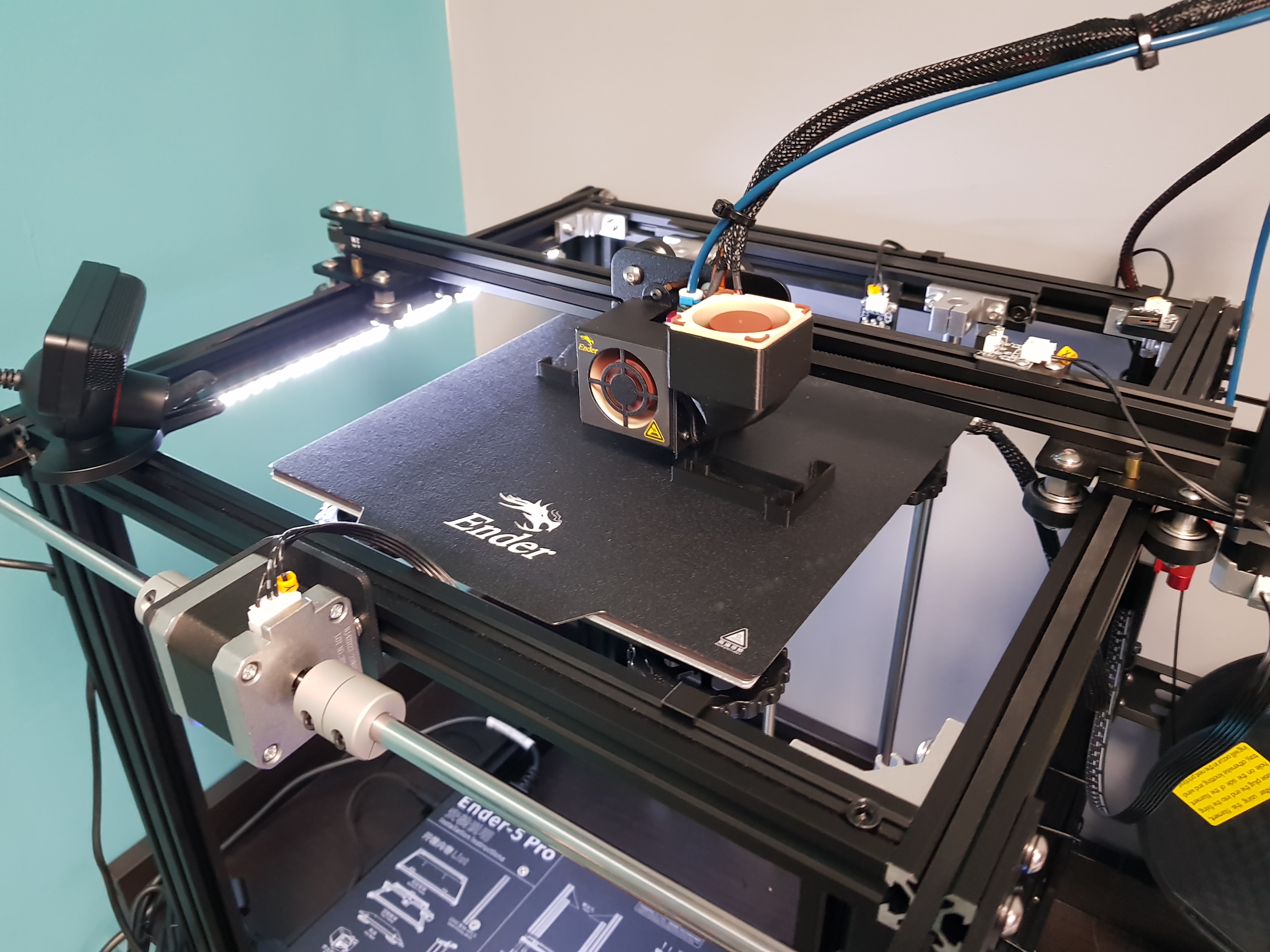
Having bought an Ender 5 Pro on the grounds that I wanted to be able to use it and didn't want to be replacing parts of it straight away or printing upgrades to it.....I've dismantled, modded and upgraded it.

The fans in the control box I changed already but now I've done the hot end fans too. The joy, of course, being to make sure that the duct doesn't crash if the head moves full scale.
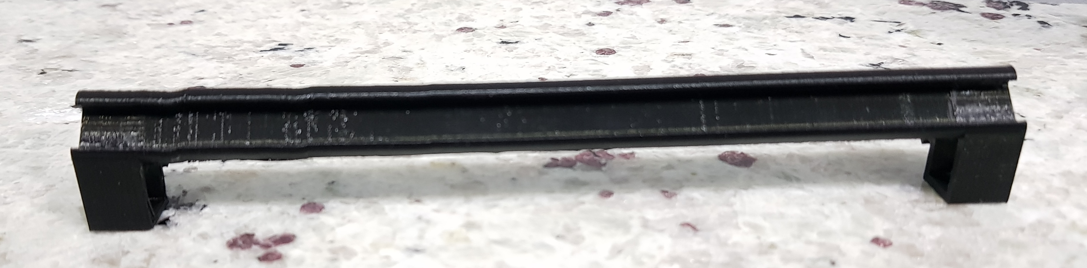
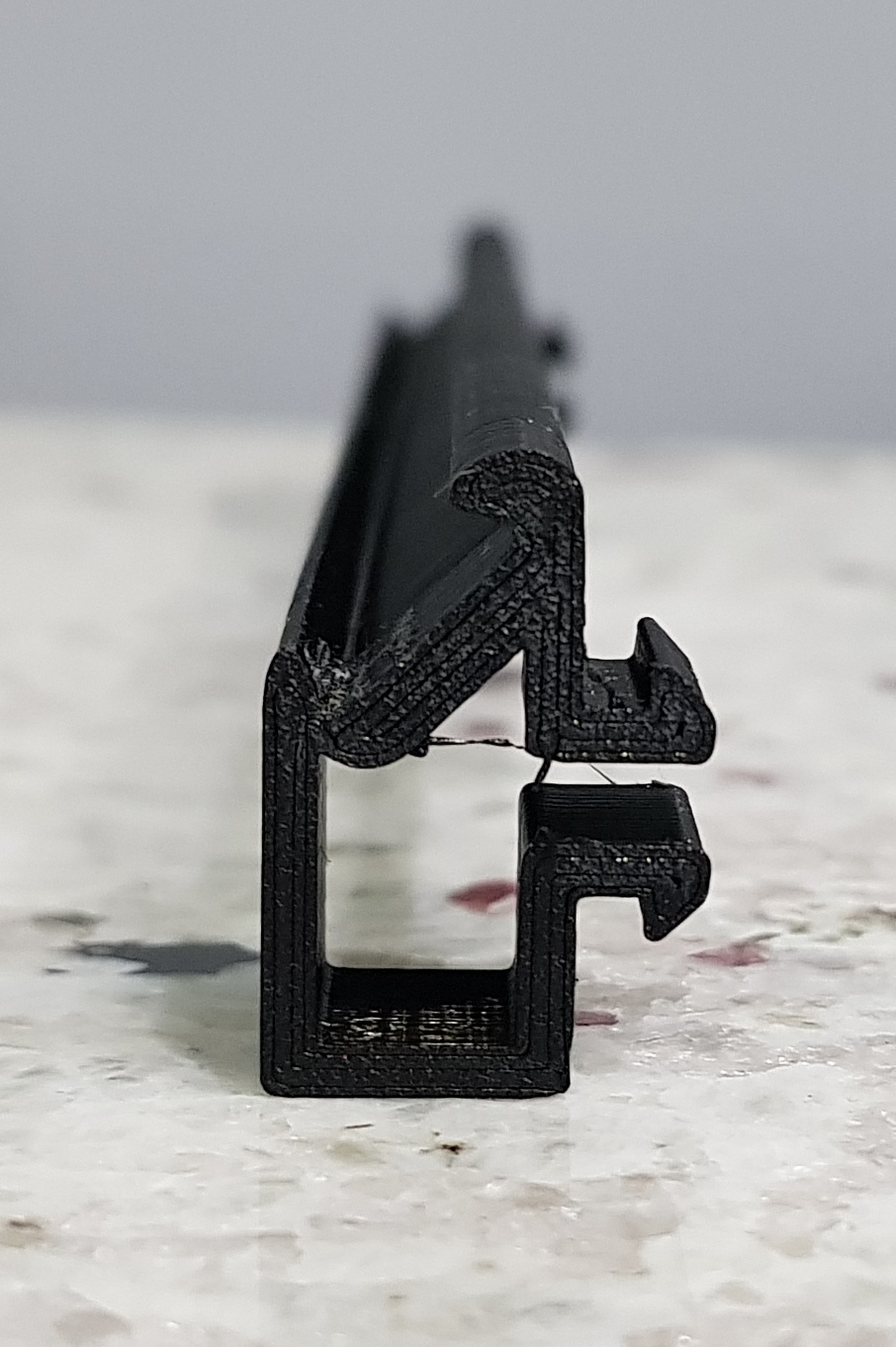
I've also made and printed some brackets to hold that light strip you can see - they just clip into the bottom slot of the 2020 extrusion - and I've added a toggle switch to turn on/off a jack socket that feeds them off the same 12V buck convertor that runs the fans.

The layer fan isn't totally quiet but that's mainly due to the fact that it's running off a really poor PWM implementation. I believe I could turn up the frequency of the PWM by modding the firmware.....but I'm not sure I'm there yet! It's a lot quieter than it was already.

The other thing that may not be obvious is that I've rebuilt it bass ackwards. This allows the Y-axis motor to be at the front instead of the back. Flipping it means that 0,0 is still in the back right corner. This means I can push it back far enough that it will fit on the work surface (39.5cm deep - nominally 40) without the front feet falling off the front. Previously I had to have a couple of planks under the feet to extend the surface....not the best of looks!

Web cam is now also mounted on a 4mm shaft that fits in the corner bracket much like the Y-axis stop does.
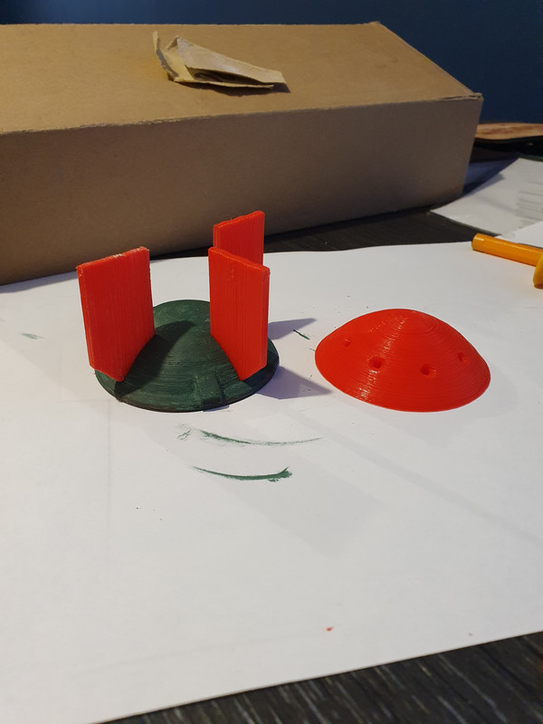
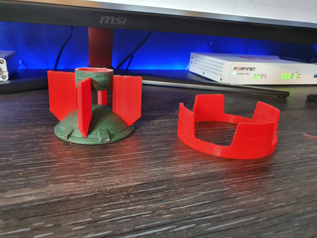
 
Soldato
OP
Joined
4 Jun 2007
Posts
2,623
Location
Watford, UK
Cheers. Since you seem to be diagnosing print issues, would you care to comment on one of mine please? The first support I printed upright at 150mm long with the intention of joining two of them to span the 300mm length. As you can see, it wobbles somewhat towards the end and that scrapped it because I couldn't slide the LED strip in. I 'foxed' the problem by printing three runs of 100mm instead but wouldn't mind knowing what the issue is called and maybe how to fix it. I was thinking it looked like lost steps but it would seem odd that it conveniently lost them in the other direction to bring it back again. The three 100mm sections all printed fine.


Associate
Joined
23 Jun 2004
Posts
2,459
Location
Macclesfield
Cheers. Since you seem to be diagnosing print issues, would you care to comment on one of mine please? The first support I printed upright at 150mm long with the intention of joining two of them to span the 300mm length. As you can see, it wobbles somewhat towards the end and that scrapped it because I couldn't slide the LED strip in. I 'foxed' the problem by printing three runs of 100mm instead but wouldn't mind knowing what the issue is called and maybe how to fix it. I was thinking it looked like lost steps but it would seem odd that it conveniently lost them in the other direction to bring it back again. The three 100mm sections all printed fine.
On a different printer I'd say it was Z-wobble, but your box-section framed printer should be pretty much immune from that as it's very stable in the z-axis (or should be!). Maybe check the belt tensioning? ...and maybe check the bed moves in Z are not sticking/binding anywhere along its full travel.
 
Soldato
Joined
26 Sep 2010
Posts
7,157
Location
Stoke-on-Trent
That print looks difficult to orient properly, Cenedd. Any which way you put it it'll need supports. Not an issue in its own right, but the wobbly bit looks like it wasn't supported properly so it's sagged. Check all of your belts are tensioned properly to prevent any drift. With your stepper motors disabled, do all axis run smoothly without any judder or banging? How much pressure do you need to apply to move teh axis manually (tip: you need practically none). Could be some of the eccentric nuts are a bit tight so you're not getting free movement. Also, is it dimensionally accurate? The layer quality looks a bit scruffy too, over extrusion maybe?

What I'd suggest is trying it again but with a really slow print speed (say 35mm/s) and see if things still wobble. If not then there's some kind of misalignment which is exaggerated with faster print speeds - I got ALL of that to diagnose once I replace my bed and replace a squished Delrin wheel after it was too tight.
 
Man of Honour
Joined
30 Oct 2003
Posts
13,259
Location
Essex
That print looks difficult to orient properly, Cenedd. Any which way you put it it'll need supports. Not an issue in its own right, but the wobbly bit looks like it wasn't supported properly so it's sagged. Check all of your belts are tensioned properly to prevent any drift. With your stepper motors disabled, do all axis run smoothly without any judder or banging? How much pressure do you need to apply to move teh axis manually (tip: you need practically none). Could be some of the eccentric nuts are a bit tight so you're not getting free movement. Also, is it dimensionally accurate? The layer quality looks a bit scruffy too, over extrusion maybe?

What I'd suggest is trying it again but with a really slow print speed (say 35mm/s) and see if things still wobble. If not then there's some kind of misalignment which is exaggerated with faster print speeds - I got ALL of that to diagnose once I replace my bed and replace a squished Delrin wheel after it was too tight.

Ahh I should have sent you a load of wheels as well I literally have about 100 or more :( Today I am printing more parts for my mini nuke! So far she is looking the bomb!


Although having a quick look it will be touch and go if there is enough pla on the spool to finish the part it is printing. This is the best PLA I have as well, polymaker stuff and it prints amazing. I guess I will just have to use one of the random spools I got given :)

I shall probably do a bit more painting and stuff while im sitting here today waiting for things to happen. It's end of month so I won't be so busy today as everybody else should be busy billing like crazy.
 
Last edited:
Soldato
OP
Joined
4 Jun 2007
Posts
2,623
Location
Watford, UK
I printed it with the length of it straight upwards. Mainly because I wanted the layer lines of the end clips to run in the direction that they would spring rather than the movement pull the layers apart but also I thought it would work and look better. So the movement is sideways rather than downwards. There was support printed between the two clips.
I definitely had issues with the rollers on the extrusion. There were definite detents as you rolled it by hand. I initially thought it was dents/chips/flatspots on the wheels but when I tested it rolling it up and down a short length of extrusion (while I had the top frame apart) I found it stuck slightly on an imperfection in the extrusion. I can't find any on the actual lengths that the Y axis runs on and the effect seems to have gone. Actually that may be a lie as I found some again. It seems to go with cleaning but I suspect it comes back again so there's definitely an issue.

I've retensioned the Y-axis belts as part of rebuilding the top frame. They're slightly tighter than the factory-set X-axis. How tight should they be set?

In terms of wheels on the Y-axis, there are four on each extrusion. I've just checked them and on the left side, the outer wheels will spin with axis still - one very easily and one with just a little resistance. This, I suspect is not a good sign. On the right side, one will free spin. The inner wheels have a hex shank and the outer a round shank so presumably the inner are adjustable by loosening the top screw and then rotating the hex and the outer not adjustable?
 
Man of Honour
Joined
30 Oct 2003
Posts
13,259
Location
Essex
I printed it with the length of it straight upwards. Mainly because I wanted the layer lines of the end clips to run in the direction that they would spring rather than the movement pull the layers apart but also I thought it would work and look better. So the movement is sideways rather than downwards. There was support printed between the two clips.
I definitely had issues with the rollers on the extrusion. There were definite detents as you rolled it by hand. I initially thought it was dents/chips/flatspots on the wheels but when I tested it rolling it up and down a short length of extrusion (while I had the top frame apart) I found it stuck slightly on an imperfection in the extrusion. I can't find any on the actual lengths that the Y axis runs on and the effect seems to have gone. Actually that may be a lie as I found some again. It seems to go with cleaning but I suspect it comes back again so there's definitely an issue.

I've retensioned the Y-axis belts as part of rebuilding the top frame. They're slightly tighter than the factory-set X-axis. How tight should they be set?

In terms of wheels on the Y-axis, there are four on each extrusion. I've just checked them and on the left side, the outer wheels will spin with axis still - one very easily and one with just a little resistance. This, I suspect is not a good sign. On the right side, one will free spin. The inner wheels have a hex shank and the outer a round shank so presumably the inner are adjustable by loosening the top screw and then rotating the hex and the outer not adjustable?

You think you have problems :)

I'm literally running full on ghetto! If anybody can out ghetto this printer then id be surprised. :D


I mean some people have nice little boxes and tidy wiring systems for their printer.... Me? I have this:


:D And yes you will note that the stop for the x carriage is taped in place with Kapton tape :)
 
Soldato
OP
Joined
4 Jun 2007
Posts
2,623
Location
Watford, UK
That's true, but I bet you have a better working knowledge of it already......less sanity left, perhaps, but all things have a price! :D
Part of me wanted to shove an Aquaero in mine so I could tell if I'd got temperature issues after I totally re-jigged the control box (and hence PSU) cooling. I can tell the Pi 3b+ is staying under 40°C though so I think it's all good.
 
Man of Honour
Joined
30 Oct 2003
Posts
13,259
Location
Essex
That's true, but I bet you have a better working knowledge of it already......less sanity left, perhaps, but all things have a price! :D
Part of me wanted to shove an Aquaero in mine so I could tell if I'd got temperature issues after I totally re-jigged the control box (and hence PSU) cooling. I can tell the Pi 3b+ is staying under 40°C though so I think it's all good.

Didn't have a choice, the board went pop so I needed to put in a new board, get the firmware right etc so currently the only thing that came with the machine was the frame everything else is different, the pitch on the rods is different, the bed is different, board, drivers... everything really. My knowledge of it is ok but I left it for about a month and all of the thermistors failed so now it has new ones. I do think ill make further changes to this bad boy and rebuild it once I get the other machine up and running and working but for now it's an absolute ghetto work horse. You press print, it prints and the quality is more than good enough, It can also print big as in 0.8mm nozzle fairly well so occasionally I wack on the big boy for the fast printing. Once I have made a electronics case and tidied up all my ghetto stuff it will look much better I am sure!
 
Soldato
OP
Joined
4 Jun 2007
Posts
2,623
Location
Watford, UK
The one tip I can offer is to make sure your electronics box is accessible. Mine is, I think, partly structural in that it stiffens the frame. It's also mounted upside down - presumably to keep falling things out. All the wires have joiners half way along them so that it's easy to put together out the box. Trouble is, the slightest problem (I'm looking at the Pi not booting or not playing nicely on the wifi here) and you have to cut all the cable ties to disconnect the cables, unscrew the box from the frame, flip it upside down and unscrew the lid. At a bare minimum, it would be preferable to be able to unplug the box without having to cut all the ties - although I've been replacing a lot of them with printed clips. Failing that, an HDMI and USB port mounted on the case would be another option so you can get to the console of the Pi. Access to the SD card would have been another good plan.
 
Man of Honour
Joined
30 Oct 2003
Posts
13,259
Location
Essex
The one tip I can offer is to make sure your electronics box is accessible. Mine is, I think, partly structural in that it stiffens the frame. It's also mounted upside down - presumably to keep falling things out. All the wires have joiners half way along them so that it's easy to put together out the box. Trouble is, the slightest problem (I'm looking at the Pi not booting or not playing nicely on the wifi here) and you have to cut all the cable ties to disconnect the cables, unscrew the box from the frame, flip it upside down and unscrew the lid. At a bare minimum, it would be preferable to be able to unplug the box without having to cut all the ties - although I've been replacing a lot of them with printed clips. Failing that, an HDMI and USB port mounted on the case would be another option so you can get to the console of the Pi. Access to the SD card would have been another good plan.

Couldn't be any more accessible than sprawled out over the table beside the machine. Perhaps just keep it like that for good measure :)
 
Man of Honour
Joined
30 Oct 2003
Posts
13,259
Location
Essex
How's it going with the one I gave you?

At the weekend I stripped it down quite a bit. I took all of the enclosure off, the electronics are out. I have the BTT SKR 1.4, colour touch screen LCD, new drivers pretty much ready for it. I was measuring the offset for the bl touch which im not sure at all is right... Don't suppose you know off hand the offsets used on the current firmware?
 
Associate
Joined
23 Jun 2004
Posts
2,459
Location
Macclesfield
I printed it with the length of it straight upwards. Mainly because I wanted the layer lines of the end clips to run in the direction that they would spring rather than the movement pull the layers apart but also I thought it would work and look better. So the movement is sideways rather than downwards. There was support printed between the two clips.
I definitely had issues with the rollers on the extrusion. There were definite detents as you rolled it by hand. I initially thought it was dents/chips/flatspots on the wheels but when I tested it rolling it up and down a short length of extrusion (while I had the top frame apart) I found it stuck slightly on an imperfection in the extrusion. I can't find any on the actual lengths that the Y axis runs on and the effect seems to have gone. Actually that may be a lie as I found some again. It seems to go with cleaning but I suspect it comes back again so there's definitely an issue.

I've retensioned the Y-axis belts as part of rebuilding the top frame. They're slightly tighter than the factory-set X-axis. How tight should they be set?

In terms of wheels on the Y-axis, there are four on each extrusion. I've just checked them and on the left side, the outer wheels will spin with axis still - one very easily and one with just a little resistance. This, I suspect is not a good sign. On the right side, one will free spin. The inner wheels have a hex shank and the outer a round shank so presumably the inner are adjustable by loosening the top screw and then rotating the hex and the outer not adjustable?

Youy should be able to turn the wheels with your finger/thumb. There should be resistance to turning it though - it should not rotate freely if you hold the carriage in place. Of course there should be no play at all if you push it side-side etc. One wheel will have an eccentric bush and the hex section allows you to rotate it to make an adjustment to take out any play. If the rubber wheels are worn they are available as spares Ebay/Amazon and easy to replace. Belts need to have no slack in them but not so tight they are like bow strings lol! If there is a lot of pressure on the the toothed wheel the bearings will quickly disintergrate (a chronic problem I had with my Wanhao 4S).
 
Man of Honour
Joined
30 Oct 2003
Posts
13,259
Location
Essex
Lads... What is the smallest nozzel you can buy and still use with normal filament? I need something small! Actually... I might just go buy the screws rather than print em. That way I can rust them up as well!

Mini Nuke!!

 
Last edited:
Soldato
Joined
17 Jul 2007
Posts
24,529
Location
Solihull-Florida
At the weekend I stripped it down quite a bit. I took all of the enclosure off, the electronics are out. I have the BTT SKR 1.4, colour touch screen LCD, new drivers pretty much ready for it. I was measuring the offset for the bl touch which im not sure at all is right... Don't suppose you know off hand the offsets used on the current firmware?


I did give you the link to the manual that told you....

Here you go https://www.antclabs.com/manual you want the V1 manual..
 
Back
Top Bottom