Ronski's Solar & battery DIY build with whole house backup

Soldato
OP
Joined
3 Dec 2012
Posts
3,641
Location
Kent, much sunnier than Scotland
Some more progress.

In the virtual world.

Powerwall.jpg


And in the real world.

Powerwall-Build.jpg
 
Soldato
OP
Joined
3 Dec 2012
Posts
3,641
Location
Kent, much sunnier than Scotland
Thanks, they certainly are, I have an Artillery Sidewinder X1, but I do need to fix a leak on the print head, been extremely useful since I got it.

The rack has space for four batteries, so about 58kWh, although it's unlikely I'll have four but possible. I expect once I've got the main expense out the way and everything is up and running I will add another. There is space for another MPPT as well, just in case I add more panels in the future.

Cable management is going to be a bit of a headache, but I'm starting to form some ideas, but will need to check some things with the electrician.
 
Soldato
OP
Joined
3 Dec 2012
Posts
3,641
Location
Kent, much sunnier than Scotland
I was looking at making my own busbar setup, but then I thought actually the Lynx set up would fit quite well, and then just run a pair of cables from each battery tray when I add another battery.

Not sure yet on the Gerbo GX, but it may be simpler in the long run.
 
Soldato
OP
Joined
3 Dec 2012
Posts
3,641
Location
Kent, much sunnier than Scotland
Got some more parts arrived today, battery/cell tester, panels clamps, and electrical parts for the combiner boxes.

Unfortunately the clamps are wrong they, they sent 35mm and not 30mm clamps.

The parts below were ordered on the 19th September from China, I ordered a couple of bits of DIN rail from the UK the next day, but that has still not arrived :(

Should also have the aluminium for the bottoms of the rack drawers tomorrow.

Combiner-Box-Items.jpg
 
Soldato
OP
Joined
3 Dec 2012
Posts
3,641
Location
Kent, much sunnier than Scotland
@SBo He did mention something about requiring an earth, but to be honest that's all above my head. I'm getting close to the stage where the house consumer unit can be replaced and a new garage one fitted, and the supply routed through the garage, not sure if he'll want to do that first then the solar inverter side of things later. I'll ask him next time I speak to him.

Here's a block diagram of the Quattro, from what I understand it will disconnect the incoming grid in a power outage. AC in 1 is the grid, AC in 2 could be a generator, but I've no plans for AC2 at the moment.

Quattro-Block-Diagram.jpg
 
Soldato
OP
Joined
3 Dec 2012
Posts
3,641
Location
Kent, much sunnier than Scotland
I've been thinking about my battery cabling, and made some changes to the design. Last idea was to have a Lynx Power In on the wall and connect all the batteries to this, but that would have meant having four pairs of cables, each approximately 3 meters long, which would get rather expensive. The reason they have to be the same length is because electricity likes to take the path of least resistance, so if the top battery had shorter cables than the rest, that battery would get used the most, and thus worn out quicker. By keeping the cables, and the rest of the circuit identical it should ensure even current draw from the full set.

So to achieve this, all battery cables will be the same length. I'll use a short vertical busbar setup on the side of the rack, the top batteries will both connect using the same bolt, one cable either side of the busbar, presumably this is OK? The bottom two batteries will connect the same way to the bottom of the busbar, and the main power take off will be from the centre of the busbar. Battery 2 & 3 cables can just snake around a bit to use up the slack.

Battery-Cabling.png


I'll do away with one Lynx power in, flip the remaining one and the shunt upside down, and connect the main battery cable directly to the shunt connections via a main breaker.

Battery-Rack.jpg
 
Last edited:
Soldato
OP
Joined
3 Dec 2012
Posts
3,641
Location
Kent, much sunnier than Scotland
How to make nice round holes - bought a set of hole punches decades ago - they've served me very well over the years.

Hole-Punch.jpg


Holes-Punched.jpg


Luckily I got the SWA pretty much spot on, this part is now ready for the electrician. SWA flange nuts left loose for his choice of earthing, and the box does need to be removed again whilst the new consumer unit is fitted for an appropriate hole to made through into the CU for the main feed in from the garage.
Also need a 32mm hole punch, which I might have at work and a bush for the hole through to the fused switch.

Fused-Switch-Adaptable-box-fitted.jpg
 
Soldato
OP
Joined
3 Dec 2012
Posts
3,641
Location
Kent, much sunnier than Scotland
Spent the day at work yesterday, didn't get as much done as I wanted, had to service the wifes car and check it over for Mot.

I got the the sides of the rack welded together, but had to drill 80 holes for where the rails will screw to. Usually I'll just clamp several bits together, and drill all the holes, but for some reason the drill bits kept snapping - probably as they are only cheap ones, and were 3mm.

Anyway, got all the holes drilled, then drilled to 4.2mm ready for tapping to M5. Got the two sides welded together, still got some more welds to do, and then clean it all up, but its coming along.

Rack-Sides.jpg


One of the showers is leaking at home, so I've now got that to sort out :(
 
Soldato
OP
Joined
3 Dec 2012
Posts
3,641
Location
Kent, much sunnier than Scotland
During in the week I discovered that my rack side had bowed during welding, really didn't expect that that to happen as the welds aren't that big. These sides need to be parallel for the drawer system to work. Currently I have the side G-clamped together with the tops and bottom spaced out, so past the point of being straight, hopefully this will work. Other option is to warm them up and straighten that way. I could also put flat bar across the front and rear to control the width.

Yesterday I had almost a full day at work, so made some good progress.

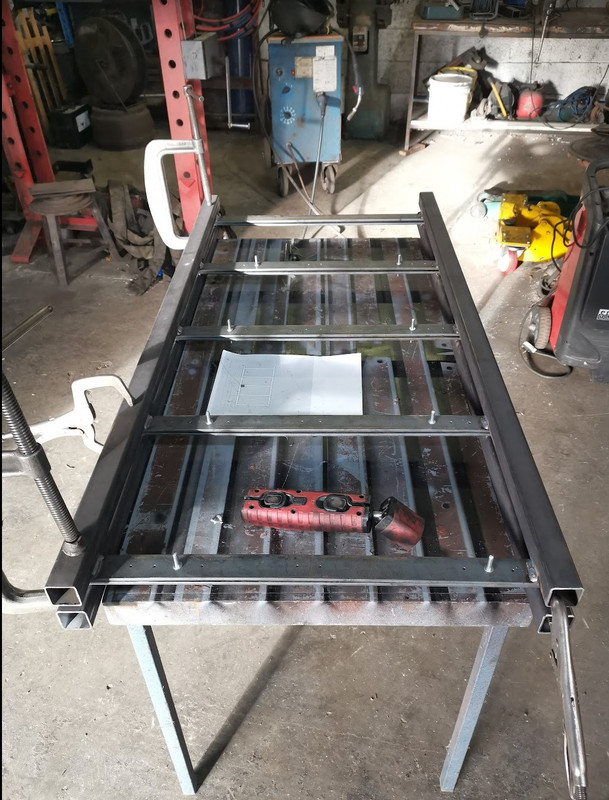
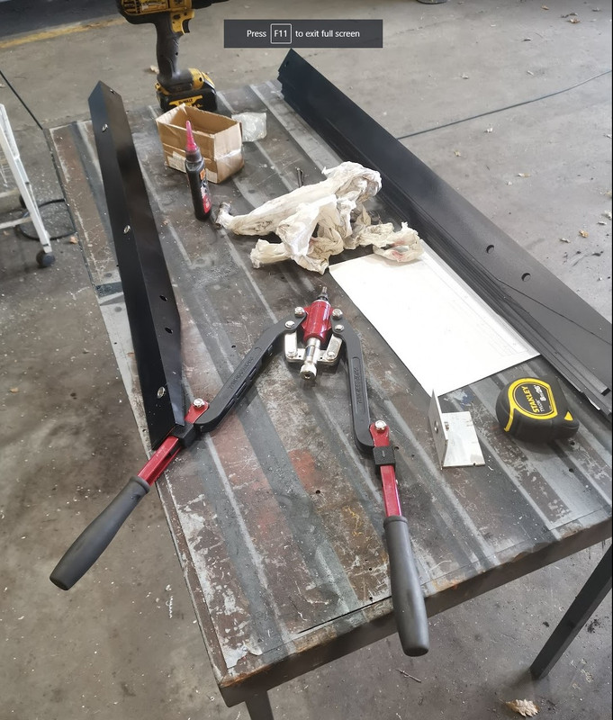
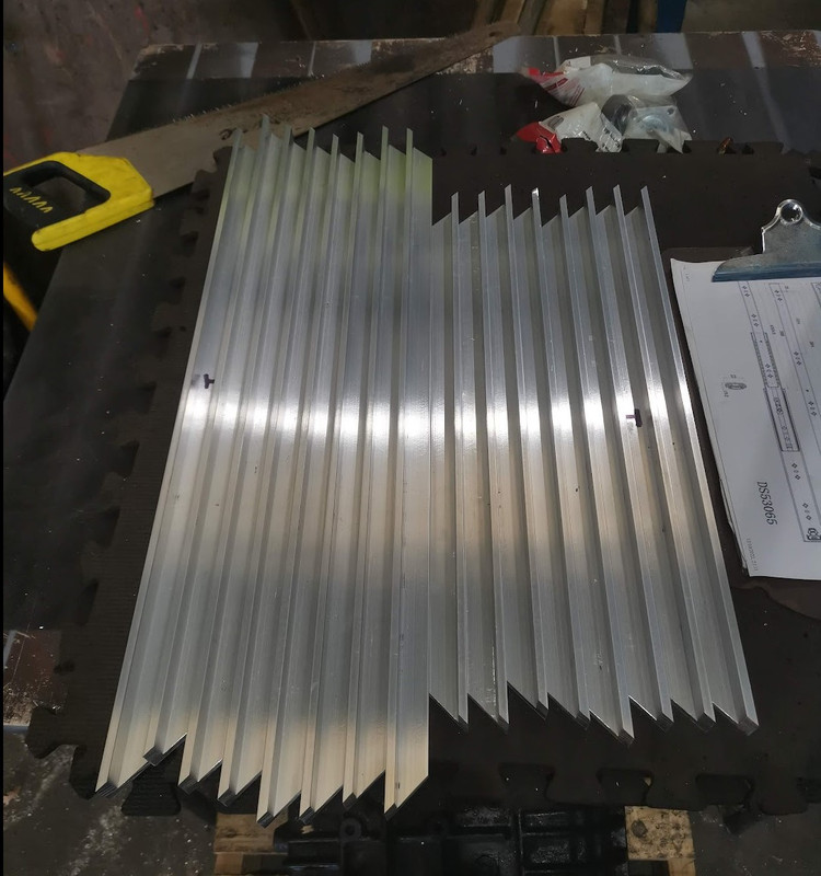
There are sixteen lengths of angle which forms the slopes of the mounting system that the panels will be clamped to, I've put three M8 stainless steel rivet nuts in each one for the panel clamps, so another 48 holes, and manully setting 48 rivet nuts, luckily we have a decent tool.


Rivnuts.jpg


I cut all the sides of the trays with my mitre saw - not the hand saw in the picture, it just happened to be there.

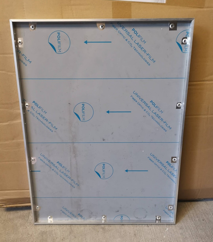
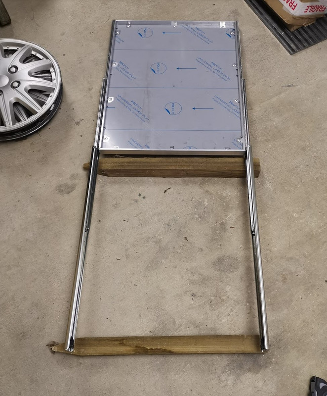
I also had to drill eight holes in each side piece, so another 64 holes for the M5 screws the drawer slide.

Tray-surrounds-cut.jpg


First tray assembled, its pretty critical each tray is the same width, so I need to be extra careful there. I would have loved to have welded these, but I don't have a TIG welder, and I've never TIG welded, so 6.4mm ally rivets it is.

The tray feel very sturdy, 25mm x 6.4mm equal angle, and a 5mm base, mind you they will be holding over 85kg of cells, so they need to be sturdy.

Tray.jpg


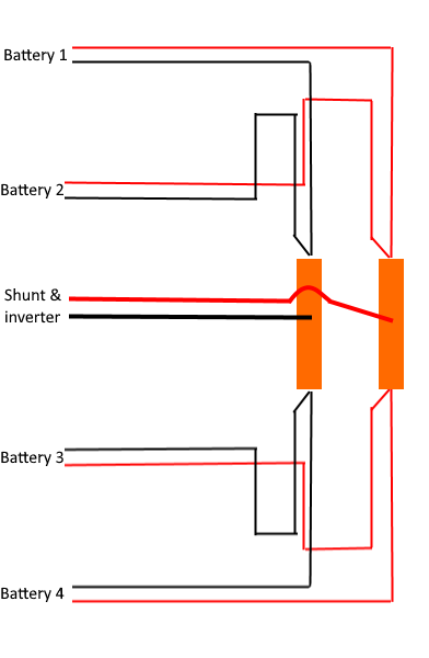
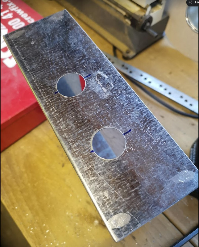
I've ordered a 400 amp and a 250 amp T class fuse, and appropriate holders, also I've ordered a 40 x 8 x 1000 tinned copper bar to make my busbar.

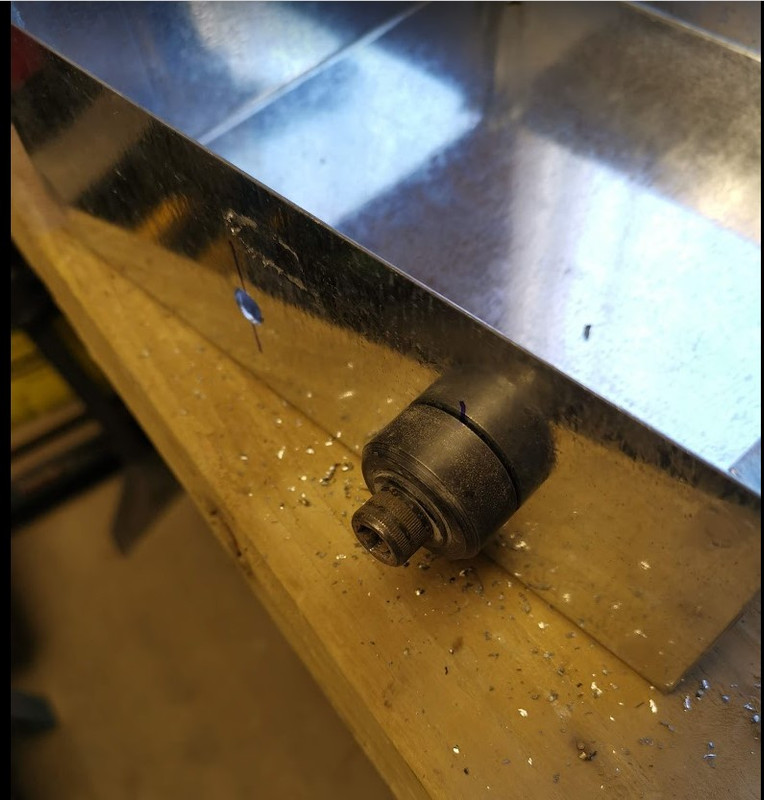
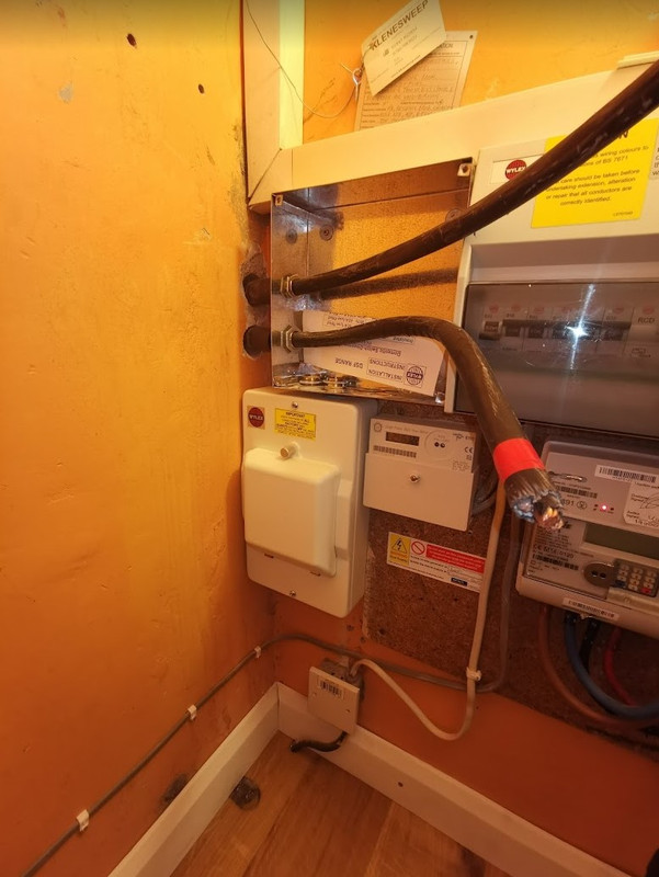
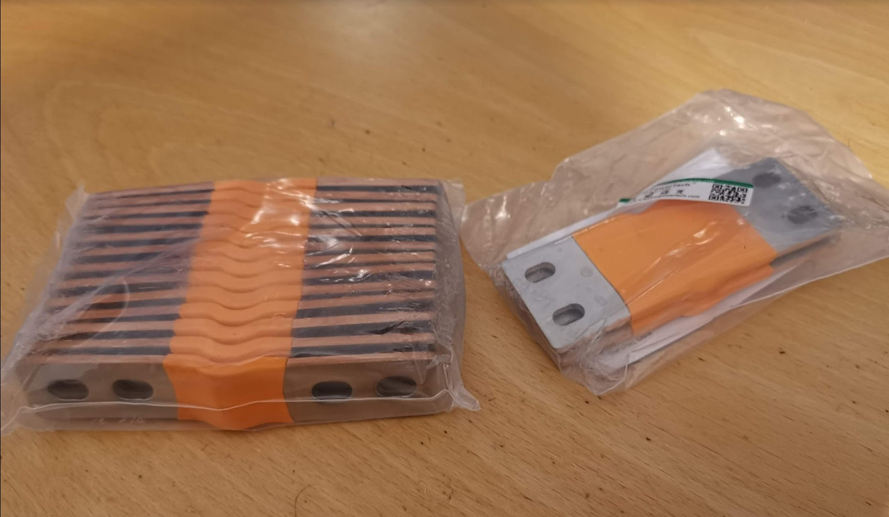
On a very important safety note, I've learnt that a lot of DC breakers are directional, wire them up wrong and this can happen which is not good! In a solar storage system there is only one place where you can use a directional breaker, and that's between the MPPT and panels. You would think you could between the MPPT and busbar, but if there is a short circuit fault in the MPPT then the current is going to flow from the battery into the MPPT, so this needs to be bi-directional, as does the main battery breaker, if you are to use one. So I'm not going to be using what I've purchased so far. The directional breakers are referred to as polarised, the non directional are non polarised, it is non polarised that I need, and they need to have the correct voltage rating as well, at least 60v DC, a lot of stuff is rated at 48v or less, which is no good. It's all to do with the ability of DC to sustain an arc, AC passes throgh zero volts at 50Hz so self extinguishes, DC does not and when you've got cells capable of passing circa 20,000 amps in a dead short you need to do it right.

I have found some suitable Noark breakers, but they don't appear to be sold in the UK, so I need to email a couple of overseas suppliers to see if they can ship them here. Other option is to just use fuses - I was going to use fuses and breakers, breakers giving the easy option to turn stuff off, but I now know what goes on when you turn something off under load.

It seems very difficult in this country to buy the correctly rated breakers, and whilst there is China I'm now not confident of what can be purchased from there - one supplier told me the breaker I'd purchased could be wired either way, but it is very clearly shown on the breaker that it is only to be wired one way, and therefore is not bi-directional.
 
Soldato
OP
Joined
3 Dec 2012
Posts
3,641
Location
Kent, much sunnier than Scotland
I actually have some of Tomzn's MCB's, but they are polarised as far as I can tell, which means they are not ideal for bi-directional use, and potentially could be a safety issue. There is a certain augment that you would have less current flowing from the charger, so you would wire it for the main current draw coming from the batteries, but still not ideal, and still a potential safety issue - that video I linked to above was at only 10 amps, but I suspect a far higher voltage as it looked to be direct from his solar panels.

I also purchased a couple of these https://www.aliexpress.com/item/1005002039194251.html?spm=a2g0o.order_list.0.0.21ef1802MZ0w3K but they also appear to be polarised.

The two Taixi breakers are 160 and 250 amp, in theory my inverter could draw 160 amp continuous , possibly more depending on battery voltage and efficiency, it can also peak to a lot higher, but not sure how long that peak is, and how long the breaker would last at over current.

The plan is to have each battery fused at 250 amp, and the whole rack fused at 400 amp, and then suitable breakers, preferably a bit lower rating than the fuses. The big Noark breakers can be adjusted down from their maximum, problem is getting hold of them, oh and rather oddly they don't seem to do two pole ones any more, just seem to be 3 and 4 pole even though they say they are ideal for solar, surely 2 pole is ideal for solar?
 
Soldato
OP
Joined
3 Dec 2012
Posts
3,641
Location
Kent, much sunnier than Scotland
Yes, that's what I'm considering doing, the Tomzn MCB's should be fine in the solar combiner as that can be wired correctly, the individual strings are also fused.

I can fuse inside the Lynx power in for the MPPT's.

Strictly speaking pretty much all the isolator switches I've seen are up to 48v, not sure if you're running 24v or 48v, but 48v is up to 58v, which the switches aren't rated for, but if I can't find anything else its what I will use.

Even Victron state 12v to 48v, but does that mean a 48v system which could have voltages approaching 60v, going by this answer it would suggest you can use it, so long as the inverter is pre charged. These types of switches should never be turned off under load, they are not designed for that, which is why I'd prefer a proper breaker on the main rack, just in case.
 
Last edited:
Soldato
OP
Joined
3 Dec 2012
Posts
3,641
Location
Kent, much sunnier than Scotland
I'm looking at ordering my panels, I need 12 and they have to be 1722 x 1134

I've short listed the following, was looking at the 405w version, but now out of stock.
JA Solar JAM54S30-395/MR Black Frame Half Cell Solar PV Panel at £147.18 each​

have also got the following on my list but at another £55 per panel don't think the extra 35w per panel is worth the extra cost.

JA Solar JAM54S30-410/MR Black Frame Half Cell Solar PV Panel at £202.49​

I did have some others on the list, but they are all more expensive, what's peoples thoughts on the above, any other suggestions/prices?
 
Soldato
OP
Joined
3 Dec 2012
Posts
3,641
Location
Kent, much sunnier than Scotland
Eurener MEPV410-T22L52A27P4 - 410W Black - 1095mm x 1760mm

How did you work out the part number, Eurener don't seem to list part numbers on their data sheets. I'm looking at the MEPV 108 HALF-CUT ICON 420w as its only 2mm different from my dimensions - my frames are not adjustable, so don't want to fit an odd ball size just in case I need to change panels later on. Any idea what the Icon bit means, or is it just irrelevant naming?

We have an Edmundson Electrical in Canterbury, so I'll give them a ring tomorrow.
 
Soldato
OP
Joined
3 Dec 2012
Posts
3,641
Location
Kent, much sunnier than Scotland
Just went on https://www.ena-eng.org/gen-ttr/Index?Action=ViewDetail&EID=54780771&tab=search to see if the Multiplus II 10000 or new Quattro II had been tested and noticed that it now says the Quattro 48/10000 is non-compliant for new installations.

Any one any idea what's happening?

It seems the Multiplus II 48/5000 is still compliant, but the GX version isn't.

Edit. Just noticed they have a Quattro 10000 dated 6 October 2022 - Awaiting assessment, perhaps a software update or something.

Quattro-non-compliant.jpg
 
Last edited:
Back
Top Bottom