Scratch build valve power amps

Kei

Kei

Soldato
Joined
24 Oct 2008
Posts
2,750
Location
South Wales
Something a little different from the usual pc builds. I've been trying to get both the time and effort to scratch build my own power amplifier for nearly a decade. Originally, I had planned on building a clone of a Quad 606, but owning and tinkering with 12 different solid state amplifiers, it just didn't really "spark" my enthusiasm enough so it got put on the back burner in 2012. Late last year a friend in work asked to borrow a scope probe as he was repairing his vintage valve amplifiers. (Leak TL12's) Which brought up the idea I'd never considered, why not scratch build a valve amp instead?

The plus points from my perspective were:
  • They look and sound great according to the hifi world (although I'll admit I've never heard one, which inspires my curiosity)
  • Point to point wiring with no printed circuit boards means very easy to modify, if a little more challenging to build
  • Fewer parts, so less to go wrong, should make fault finder much easier
  • Valves are more resilient to problems in the circuit and are less likely to catastrophically fail unlike transistors and mosfets
  • Valves are still in production so no issues buying parts (unlike certain older mosfets/transistors)

Disadvantages:
  • Transformers and chokes used can cost a small fortune
  • Valves aren't dirt cheap like transistors
  • Valves wear out with use
  • Valves can be susceptible to external noise and can be microphonic
  • The high voltages used require considerable care to avoid an early departure from this world

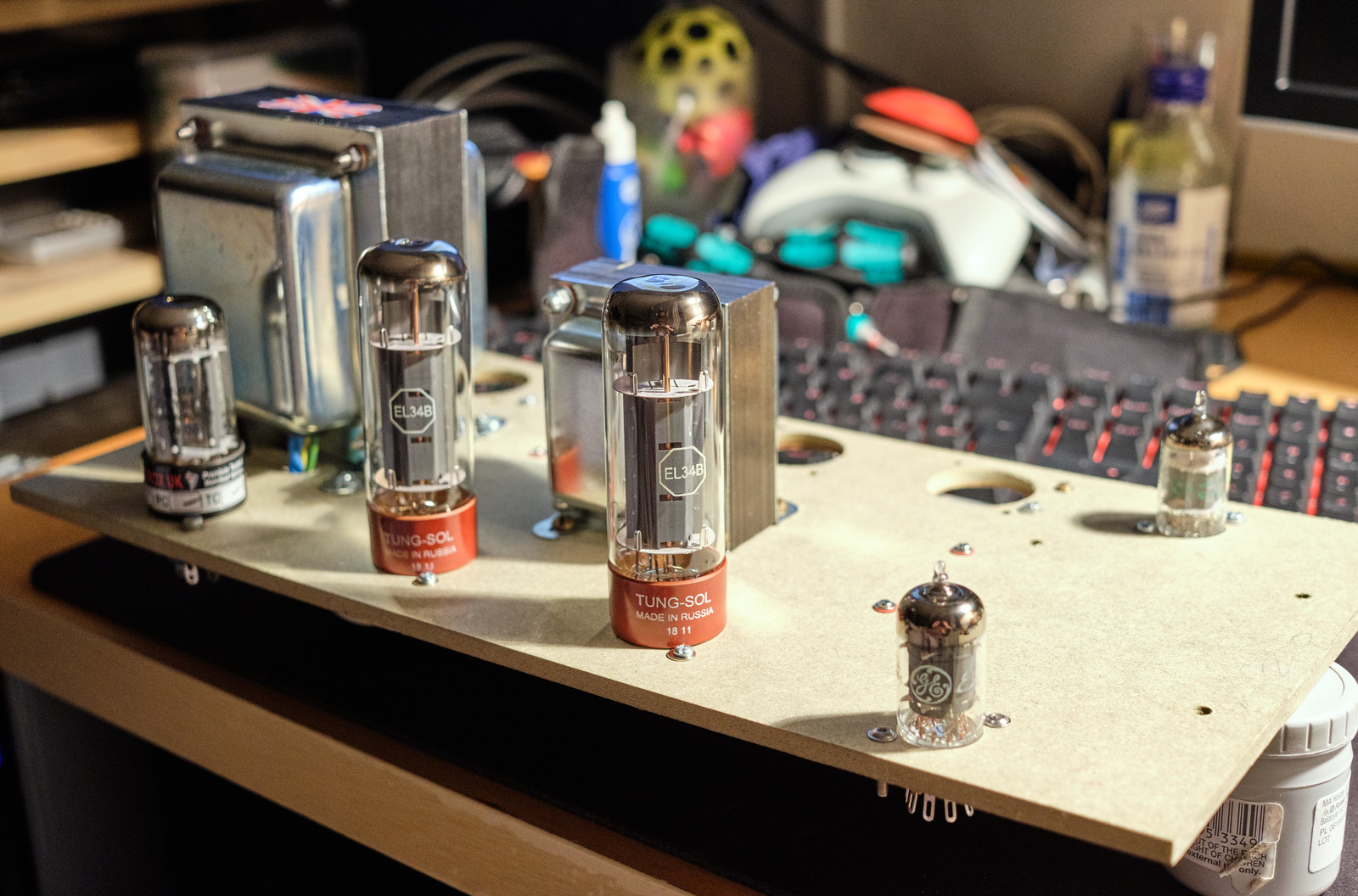
Having spent some time looking around for something to work with, I came across a book by the British valve manufacturer Mullard called, Circuits for audio amplifiers. In said book were a few different designs one of which piqued my interest, the 5-20, so named because it uses 5 valves and would happily produce 20W. It might not sound like much to some, but 20W is more than sufficient to shake the windows, rattle the furniture and severely annoy my neighbours. The topology was used in many successful commercial designs that are very well regarded. (Dynaco ST70, Harmon Kardon Citation V, Eico HF60 & Beam Echo Avantic DL7-35 to name a few)

Schematic for said build.


I'll be building them semi faithfully to the original design with a few tweaks here and there to improve reliability and safety along with adjusting the chassis to suit my requirements.
 
Last edited:
Associate
Joined
28 Jan 2015
Posts
680
MV5BMGM2YWQxZDUtZDYwMS00M2JhLTllMGEtNzQ5ZTg2ZmVlYTFmXkEyXkFqcGdeQXVyMTA2NjY2NzQ0._V1_.jpg
 

Kei

Kei

Soldato
OP
Joined
24 Oct 2008
Posts
2,750
Location
South Wales
^That would be the wrong Mullard. :p

The first priority was to order the transformers and chokes as they are usually wound to order so take 3-6 weeks to arrive. (if the manufacturers are not overrun) Since the output transformers can make or break the sound of the whole amplifier, I opted for Sowter as they are renown for transformers that have vast bandwidth covering the audible range and beyond. The only off the shelf choke I could find that fits the design was from Variable Voltage Technology on the Isle of Wight. The HT transformer I chose a Primary Windings part as it was by spec the same as VVT but slightly cheaper with a decent reputation. So 2x Sowter UA-21 output transformers, 2x VVT VTL12158-1440 Chokes and 2x Primary Windings HT transformers were bought. (at considerable expense)

I tweaked schematic with altered fusing to improve safety and solid state diodes added to help protect the valve rectifier. (all provided by the helpful folk at diyaudio)


The standard Mullard tag board design.
49567179392_a53cbc81db_h.jpg


My tweaked version to make for shorter and tidier cable routes between the board and the other components as I intend to build a different layout that is similar to their 5-10 amplifier.
49573040081_550982ef9a_h.jpg


The board placed in with the other components in their approximate positions (where possible)


I then drew up a rough cad design to show the approximate finished design layout. The frame will be made from wood and the main base plate will be aluminium ~3mm thick. I'm thinking of using Shaeffer AG for machining a pair of panels for the final design.
49531772536_dff1035330_h.jpg


I also had a dig through my component stashes in the loft and shed to see if I already had some parts which would save me having to buy them and came up with the following.
6x Octal sockets
2x 250V 5x20mm fuse holders + boots
1K 1/2W metal oxide resistors
47pF capacitors (both ceramic and polystyrene)
330pF capacitors (both ceramic and polystyrene)
47nF 600V polypropylene capacitors (which might be too long)
Standoffs
8x Rubber feet
2x Neutrik RCA sockets
Reel of 18 SWG tinned copper wire
Assorted hookup wire
Assorted sleeving
Assorted barrier strips
250mA 1KV 6.3x32mm F type fuses for the HT
2A 250V 5x20mm T type fuses for the mains
49554062892_591b6a88ed_h.jpg

49554062267_3a04053e8c_h.jpg
 
Last edited:
Soldato
Joined
28 Dec 2017
Posts
8,451
Location
Beds
******* subbed mate :cool:

I'll try and dig out pictures of the guitar amp I made in 2013. Clone of a Fender Tweed Deluxe, wasn't the neatest wiring but I learned a lot.

I'm guessing you've read it somewhere already but the best single bit of safety advice is "always work with one hand behind your back" if the chassis is open. A 450V shock down your arm to ground is much less nasty than one up the arm, across your heart and back down the other arm into chassis ground.

Looking forward to seeing this progress!
 

Kei

Kei

Soldato
OP
Joined
24 Oct 2008
Posts
2,750
Location
South Wales
******* subbed mate :cool:

I'll try and dig out pictures of the guitar amp I made in 2013. Clone of a Fender Tweed Deluxe, wasn't the neatest wiring but I learned a lot.

I'm guessing you've read it somewhere already but the best single bit of safety advice is "always work with one hand behind your back" if the chassis is open. A 450V shock down your arm to ground is much less nasty than one up the arm, across your heart and back down the other arm into chassis ground.

Looking forward to seeing this progress!
Awesome, I love a bit of DIY audio. Indeed I have seen that advice RE the hands, and I most certainly am taking it. Having shaken hands with the mains on more than one occasion in my youth, I don't fancy getting any shocks from anything worse.

For those interested in the cost of such an amplifier. This is the near complete "bill of materials". Just to add, the Sowter output transformers were far from the most expensive option and were still pretty painful on the wallet.

I bought all of the valves, turret boards, turrets, noval sockets and capacitor clips last week which leaves just the components.
49566587096_188df1cd5a_h.jpg


I went for new old stock input valves in the form of GE 6267 for the EF86 (american equivalent) and a GE JAN 5751 in place of the ECC83/12AX7 dual triode phase splitter as it has a little bit less gain. Not sure who made the 6267 for GE as they are west German, but the 5751's are USA made. Hopefully the older valves will perform well.
49554061777_ed3202f405_h.jpg


For the output valves I went with new russian made Tung-Sol EL34B and Sovtek 5AR4 for the rectification.
49557623968_6549c2bd87_h.jpg


Components roughly laid out on an initial scale drawing of the amp. The component positions were slightly out as I had under estimated the capacitor clamp size as I had no dimensions for them at the time. The chassis is currently 400x200mm. Some further tweaks on advice from diyaudio has suggested upping the first filter capacitor to 47uF which will help improve PSU ripple smoothing. I'm limited by the valve rectifier here as they recommend not exceeding 60uF.


From here on, updates may be a little slow as I'm still waiting on the transformers and chokes to arrive as it's only been 3 weeks since I ordered them and they estimated 4-5 weeks.
 
Last edited:

Kei

Kei

Soldato
OP
Joined
24 Oct 2008
Posts
2,750
Location
South Wales
Chokes arrived today. Undecided what I will do with the end bells. I may polish them up, I may paint them. Still waiting on the rest of the transformers.
 
Last edited:

Kei

Kei

Soldato
OP
Joined
24 Oct 2008
Posts
2,750
Location
South Wales
Spent the weekend building a prototype top panel using a scrap of MDF to help prove the concept. Some small tweaks may be needed to the noval socket cut outs, but it seems to work quite well.

Didn't have any M2 bolts that were long enough to attach the turret board but it fits in place properly nonetheless.


With the valves fitted into the sockets. Still waiting on the other transformers. Will sort ordering the components this week to I can start to build the turret boards.


Should look pretty good in aluminium
 
Last edited:

Kei

Kei

Soldato
OP
Joined
24 Oct 2008
Posts
2,750
Location
South Wales

First of the components have arrived.

F+T 47uF 500V capacitors for primary filtering.
1/2W PRP metal film resistors in 82K, 180K, 270K & 470K.
The rest will be other brands coming from mouser. (Dale, ohmite, sprague, nichicon and TDK)
 
Last edited:

Kei

Kei

Soldato
OP
Joined
24 Oct 2008
Posts
2,750
Location
South Wales
Rest of the parts arrived today.
49621689971_8cdf6dcfab_h.jpg


The main filtering capacitors have caused some annoyance as they didn't state anywhere in the datasheet that these were stud mounted. Still, not the end of the world and the main reason why I cobbled together a prototype on some scrap wood.
49624255931_6320bc703d_h.jpg


Ironically, the other problem I encountered is that the "30mm" capacitor clips are clearly not 30mm as they don't clamp onto the F&T caps which are definitely 30mm. It's close but roughly 1mm too big.


So with the above issues, I'll need to adjust the way the caps mount to the plate. I'm not sure I want 3 big M6 nuts sitting on the top surface as I get the feeling it'll look like a bodge. (plus they are 95mm long including terminals which would be a bit tall) I'm thinking of mounting them to the side using threaded inserts and using a normal nylon vertical mount for the F&T.
 
Last edited:

Kei

Kei

Soldato
OP
Joined
24 Oct 2008
Posts
2,750
Location
South Wales
I've decided that the best approach due to the way the stud mounting caps look is to mount them inside the chassis, but away from the valves. Vertically mounting these outside the chassis would look a bit daft. All 4 capacitors will mount on the one side panel horizontally, underneath the HT transformer. The chassis side panels are going to be ~75mm high which seems to be sufficient to fit them in with decent breathing room. I'm looking at using threaded inserts into blind holes in order to mount them without having to use a nut on the outside of the chassis.


I also laid the components out on the turret board to get a feel for the spacing and where the turrets will need to sit. It seems I may have room to spare. I left the two small pF caps out as they are really tiny.
49624256471_b4a62a60a5_h.jpg
 
Last edited:

Kei

Kei

Soldato
OP
Joined
24 Oct 2008
Posts
2,750
Location
South Wales
Made a start on the boards today. Only had a limited time, meaning I didn't get particularly far.
49631726368_bf4b4e525c_h.jpg


I also got the dispatch email for the HT transformer today, so hopefully they will arrive early next week.
 
Last edited:

Kei

Kei

Soldato
OP
Joined
24 Oct 2008
Posts
2,750
Location
South Wales
Came up with a better design for the mounting of the capacitors. Using an L section of metal between the top surface and the capacitor allows two to be located along the side which will make the cables much shorter. The other two will remain on the back panel close to the HT transformer and rectifier. The approximate layout would be as shown except the IEC socket and two caps on the back panel will mount further down the side panel giving more space between them and the upper panel.
49635153257_6390b4cbda_h.jpg


I also finished constructing the first board all bar two capacitors. (one I forgot to buy and the other I've not yet mounted in the feedback path)
49634880151_001dbc2b0e_h.jpg
 
Last edited:

Kei

Kei

Soldato
OP
Joined
24 Oct 2008
Posts
2,750
Location
South Wales
HT transformers turned up today. They look pretty well made. The mounting hole spacing doesn't quite match the datasheet even though all the other dimensions are correct.


Up against the choke on the planned layout. Coming together quite nicely.
49649682096_a6ab681317_h.jpg
 
Last edited:

Kei

Kei

Soldato
OP
Joined
24 Oct 2008
Posts
2,750
Location
South Wales
Spent today making some L brackets to mount the capacitors and drill the holes to mount the HT transformer. The astute may notice that I've mounted everything upside down so the turret board connections are backwards. It's currently just a test fitting and simple to flip everything over to the opposite side of the board. It's provided a very useful guide to making sure I get the front panel design version correct for things like countersunk holes and any engravings. The L brackets were 30mm wide which I've decided is too tight for the nuts either side of the capacitors, so I've revised that up to 35mm.
49659759327_501c2bb486_h.jpg


Transformer in position.
49658939868_5c6fc31104_h.jpg


Ironically, I've been working on a redesign as there would be rather a lot of empty space due to the capacitors now mounting on the inside of the chassis. In this version, the gap between the EF86 & ECC83 would be the only empty bit. I've got another spare piece of MDF like the one I've used, so I will probably build this one too.
49659759712_acfcbc8f25_h.jpg


The scale drawing of the revised layout
49659535391_b13e8c2c0a_h.jpg
 
Last edited:
Permabanned
Joined
9 Jun 2009
Posts
11,904
Location
London, McLaren or Radical
Very cool, I've wanted to do similar.

I've had 2x valve amps in the past... my favourite being 2A3 based and I improved it by upgrading to some Sophia electric handpicked things, they were quite magical.

They are very sensitive to the cleanliness of the power supply, highly recommend a cleaner... even if it's only a basic one. Without it, even in Switzerland which has a much cleaner supply than the UK, there can be quite a lot of base noise.


Always always wanted to experience a truly high end valve amp with some proper horns like this:
ghJZbN3.jpg


I've since moved back to solid state though, there's something magical about McIntosh for me and no more noise annoyances.

Enjoy the task!
 

Kei

Kei

Soldato
OP
Joined
24 Oct 2008
Posts
2,750
Location
South Wales
Very cool, I've wanted to do similar.

I've had 2x valve amps in the past... my favourite being 2A3 based and I improved it by upgrading to some Sophia electric handpicked things, they were quite magical.

They are very sensitive to the cleanliness of the power supply, highly recommend a cleaner... even if it's only a basic one. Without it, even in Switzerland which has a much cleaner supply than the UK, there can be quite a lot of base noise.
Always always wanted to experience a truly high end valve amp with some proper horns like this:

I've since moved back to solid state though, there's something magical about McIntosh for me and no more noise annoyances.

Enjoy the task!
Can't see me getting into horn loaded speakers due to an exceptional lack of room, I'm remarkably happy with my vintage tannoy dual concentrics. Grounding is going to be the big nightmare along with layout of the components as this plays the biggest part in minimising audible hum. I've got the feeling it will be quite a difficult challenge to deal with, particularly as I have made alterations to the original layout and it is a very high gain design with the EF86 input stage run as pentode. I plan to convert the EF86 to run as triode after proving the concept as this will bring the gain down, but it will also require some feedback network adjustments.

Thankfully, Sowter dispatched the output transformers yesterday which have just arrived today. I was very worried that these would not be turning up this side of summer due to the human malware issue. I've checked all the holes and thankfully they all line up nicely, so fitting to the test bed should be very easy provided I can find some suitable nuts/bolts.
 
Last edited:
Man of Honour
Joined
13 Oct 2006
Posts
91,139
How did I miss this thread - I've spent many happy hours building lower end speaker and headphone opamp based amps but not got into proper speaker/valve based amps so can appreciate some of what you are doing here.

The higher voltages and use of transformers haven't had me rushing towards these kind of projects.
 

Kei

Kei

Soldato
OP
Joined
24 Oct 2008
Posts
2,750
Location
South Wales
How did I miss this thread - I've spent many happy hours building lower end speaker and headphone opamp based amps but not got into proper speaker/valve based amps so can appreciate some of what you are doing here.

The higher voltages and use of transformers haven't had me rushing towards these kind of projects.
I can't deny, I have never enjoyed working on equipment with HT. CRT's were always a bit nerve wracking.

Found some suitable nuts, bolts and washers to fit the transformer to my wooden amp test build. Hopefully I'll construct the updated layout on another piece of MDF over the weekend. I'm hoping radio spares dispatch the bits I ordered today as that is all that remains in order to fully build this so I can test it.
49694760921_c561761090_h.jpg


The more troublesome factor in all of this is that I was going to use Schaeffer AG to machine the aluminium top panels in Germany which is unlikely to happen for quite some time.
 
Last edited:

Kei

Kei

Soldato
OP
Joined
24 Oct 2008
Posts
2,750
Location
South Wales
Remainder of the essential parts. Yet again I've slightly mucked up my order and only ordered 2 HT fuse holders instead of 4, so I have enough for one amp only, which isn't the end of the world.

2mm fibreglass sleeving in both red and black, which will be handy for some of the spaghetti.
30mm capacitor clamps that actually fit
Power switches, 5A/250VAC vandle proof push button on off switches (12V orange LED if I can be bothered to wire it up)
6.3x0.8mm JST flag crimps
M3 solder tags to help distribute the ground bus wire on standoffs
22nF MKP film capacitors (the bit I missed when I ordered the bulk of the components from mouser)


Technically, I'm still lacking high voltage rated barrier strips for the B+, 4mm banana sockets for the speaker binding posts, threaded insulated standoffs for the ground bus, lacing chord to help keep the looms neat and some 16 gauge tinned copper wire to use for the ground bus. (unless the 18 gauge I have is sufficient)
 
Last edited:

Kei

Kei

Soldato
OP
Joined
24 Oct 2008
Posts
2,750
Location
South Wales
Spent several hours over the weekend making some supports for the base plate with all the necessary cutouts for fuses, sockets, switches and capacitors.
49717432556_93bd79f4cf_h.jpg


With all the transformers and the valves fitted. It's already a serious case of spaghetti inside and that's nowhere near all the wiring. :eek: 
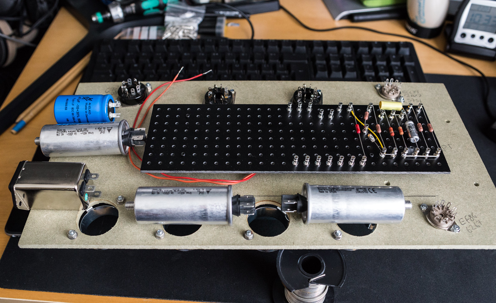
I Think These may well be too narrow as it's seeming a bit snug on the inside.
49717743627_bf77eccbdf_h.jpg


In anodised/machined aluminium, I reckon this is going to look pretty good.
49717431876_78dafcb296_h.jpg
 
Last edited:
Back
Top Bottom