Scratch build valve power amps

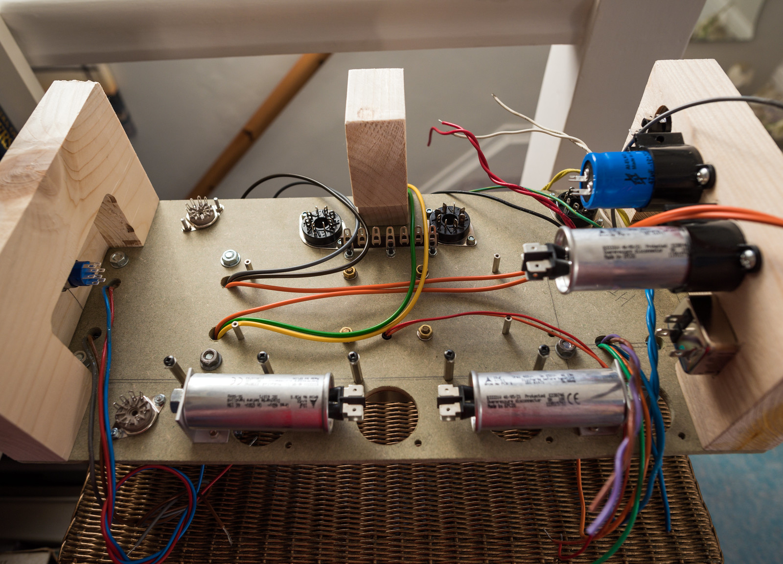
I've notched the central support to allow for the wiring to the EL34's and added a tag strip for the anode/UL connections from the output transformer. Will be looming the pairs together when I build it. I've also fitted the ground bus bar supports.
49731929411_2d234d9715_h.jpg


With the turret board in position. I'm not going to bother with the power switch for the time being as the position and the wiring to it is not easy to achieve. It's something I'll be looking into figuring out further down the road. The screwdriver bits mark the position of the ground bus wire.
49731929051_d5d12c566a_h.jpg


I'll look at adding some small side panels on which will help to brace the end panels as well as allow mounting of the input socket. The MDF does have a moderate degree of flex when I lift it to move it around, which isn't a surprise considering this thing weighs nearly 12Kg.
 
Last edited:
Made a start on the wiring today. The grounds have been left loose for now as that's tomorrows job. Hopefully I'll be able to do a test run tomorrow and see what voltages are like. (sans tubes obviously at this stage) I've loomed the various wires together up the centre to try and keep things neat.


The HT and heater wiring around the rectifier is a tad messy as I really didn't want to cut the leads too tightly in case I need to alter the layout.


With the turret board in position.
 
Last edited:
Are those power and signal cables in the middle or just signal? Convention in guitar amps is largely to have wires cross at right angles when possible. Then twist together power supply wire pairs, and run them around the corners of the chassis or at least as far from signal wires as possible.

It's always just mitigation though, some proximity/crossing over is inevitable. I build an amp once that was beautiful until the last few wires, and somehow finishing it off just spoiled all the neatness. Cable management in a nutshell for me :rolleyes:
Orange is the rectified/filtered B+ feed to the output transformer. Grey/green go to the anodes of the output valves and brown/yellow are the ultralinear 43% taps that go to the screen grids of the output valves.
 
Finished up the ground bus today and did a quick test run on the mains transformer with no valves in place to see what no load voltages I got.

HT - 414V
Heater 1 - 5.1V
Heater 2 - 3.18V
Heater 3 - 3.18V

Seems pretty close with no load so will probably be a tad low when loaded.
 
Today's progress wiring things up. Bar the heater wiring, the EL34 sockets and the ECC83 sockets are completely wired up. I've got to make another small notch in the central support so the heater wiring can pass through avoiding close proximity to the rest of the wiring to the sockets. I've also got two slim pieces of MDF that I will use as side panels which ought to help brace things as well as provide a mounting point for the input socket and speaker outputs.

Mid way through the day.


Done for the day.
 
Last edited:
Today's progress wiring things up. Bar the heater wiring, the EL34 sockets and the ECC83 sockets are completely wired up. I've got to make another small notch in the central support so the heater wiring can pass through avoiding close proximity to the rest of the wiring to the sockets. I've also got two slim pieces of MDF that I will use as side panels which ought to help brace things as well as provide a mounting point for the input socket and speaker outputs.

Mid way through the day.


Done for the day.
It certainly looks awesome
 
It certainly looks awesome
Thanks. It ought to look significantly more awesome when I get the metal chassis machined.

Today's progress.
Side panels cut and fitted along with the input socket. Speaker output sockets will be fitted when they arrive tomorrow.


Heater wiring probably isn't the best as it's my first go at it and it is definitely quite difficult, especially with stranded wire. All that is left to sort now is the heater wiring to the input valve.
 
Last edited:
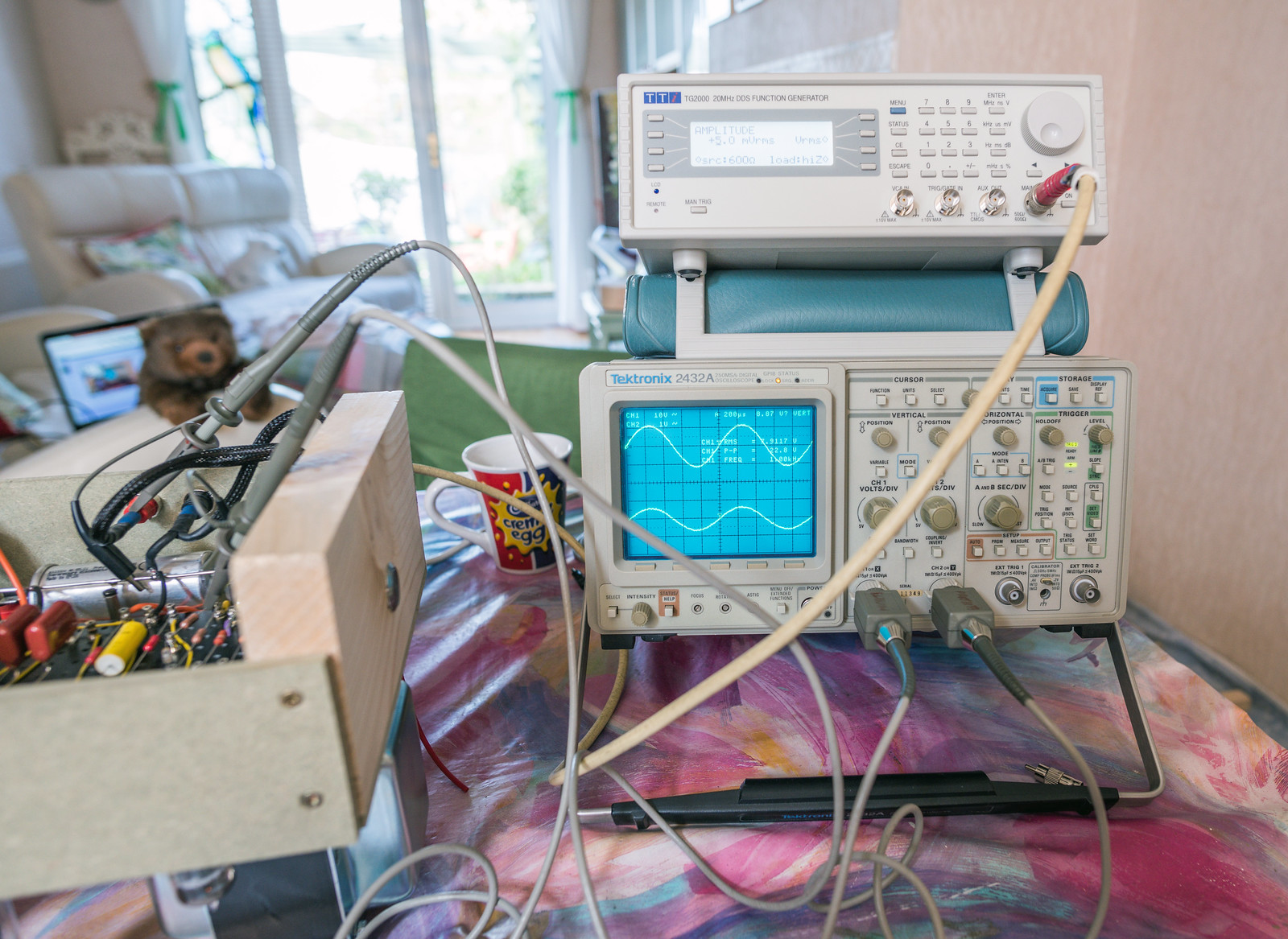
Bought a TTi TG2000 signal generator in the bargain section on CPC for roughly 40% of it's normal going rate. Very handy to have since my Lindos LA101 is playing up for some reason.
 
Last edited:
Bought a TTi TG2000 signal generator in the bargain section on CPC for roughly 40% of it's normal going rate. Very handy to have since my Lindos LA101 is playing up for some reason.
Lush. Didn't event occur to me I'll be needing my scope but it'll be useful if things don't go well.

You've inspired me to dig out a guitar amp kit I bought 5 years ago. Cleared the kitchen table and I plan to use my 5 day weekend to finish it :)
 
Lush. Didn't event occur to me I'll be needing my scope but it'll be useful if things don't go well.

You've inspired me to dig out a guitar amp kit I bought 5 years ago. Cleared the kitchen table and I plan to use my 5 day weekend to finish it :)
Knowing my luck, this prototype build will work perfectly and when I reconstruct it in the aluminium chassis, it'll not work properly. Good luck with your build.

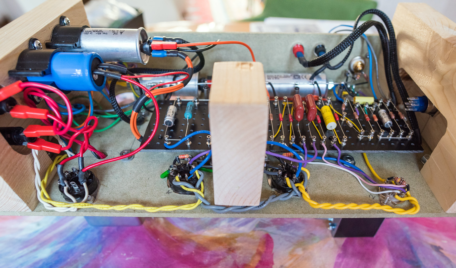
All of the wiring is now complete. Decided that I'd used excessively thick cable to the heater on the ECC83 so I dropped down a size for the EF86 as it has fairly low current draw. 4mm banana terminals fitted and only the 8 ohm tap wired up. I'll tie off the 16 and 4 ohm taps.


Last edited:
Went through the whole thing today with my father and spotted only one mistake. Went from pin 6 on V3 to C11 and pin 6 on V4 to C10 which was backwards. I also decided to rewire the heaters on V2 and V3 as the gauge of wire was more than needed.


Re-ran the unloaded test this evening and checked the voltages, all fine with no issues. Then tested with the valves in place. B+ peaks at 496V which is a tad too close to the 500V rating on C15 but it falls back to around 450V pretty quickly. Other voltages seemed fine, the valves glow seemed normal and the transformers remained cool but there was quick a lot of buzzing and my dummy load got very hot fairly quickly which was a tad worrying as there was no input connected. I didn't have enough test gear connected for me to feel comfortable leaving it run any longer at that stage. I've got the feeling that it may be oscillating. I will be testing it again tomorrow but with a lot more test gear connected including a scope across the output.
 
Last edited:
Tested again this morning and got this...

39Hz square wave at 47V p-p.


The good folk at DIYaudio pointed me at the feedback loop being connected backwards. Disconnecting the feedback was on my list of things to try. Just done it and that did the trick. No signal of any consequence out with no input. Testing with the signal generator connected and a simple 1KHz sine input.

Yay... though, holy gain batman 0.05V input, 8V output. (that's 8W into 8 ohms)
 
Last edited:
And it's now sorted with negative feedback connected. I've swapped the anode/UL connections between the two output valves. Tested it with a dummy load for a while getting a load of measurements and checking waveforms.

Voltages - I think some of the higher voltage readings are down to my fluke 28 having a different resistance to the Avometer used for the numbers in the book.


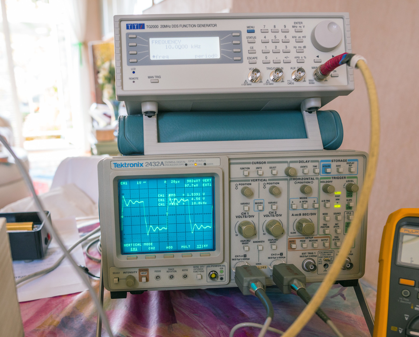
1KHz square wave input shows some ringing. Suggests HF instability.


10KHz square wave input also shows more ringing Sine looked clean out to 50KHz.


Testing with audio and one of my old DIY Kef based speakers. Sounds good and the best news is that it is completely silent, with minimal hiss audible at the tweeter and no hum.
 
Last edited:
That does look like ringing rather than high frequency boost according to this article:

https://sound-au.com/articles/squarewave.htm

Figure 5 talks about ringing - says can be a resonant circuit in the device, but also can be due a transformers' resonant frequency. And if it's outside audible range it's probably not an issue.
It's something that can be adjusted by tweaking the value of C8 in the feedback network. Raising it's value very slightly can reduce the ringing without having a significant effect on the HF response. Going too far can have adverse effects on the HF response and early signs are detectable by ear, usually described as brittle sounding. Ironically, looking at the ringing, it's in the 70-80KHz region which based on further reading on the Mullard 5-20 design seems to be a common oscillation point.

Without any negative feedback, the performance resembled figure 3 in ESP's diagrams.

To be fair, I left it playing music from my phone all afternoon to "run it in" and prove that it was working properly. It sounded fine albeit a bit strange listening to music in mono.

Try some liberal use of 0.1uf and/or 0.01uf ceramic caps see if it goes away.
Based on a lot of reading, I don't think vacuum tubes react in the same way as solid state devices due to things like miller capacitance etc. The liberal use of transformers and chokes seem to have some effects that I'm not used to.
 
Based on a lot of reading, I don't think vacuum tubes react in the same way as solid state devices due to things like miller capacitance etc. The liberal use of transformers and chokes seem to have some effects that I'm not used to.

Yeah not an area I've much experience of - but I generally find the liberal use of 0.1uf caps hide a multitude of sins hah especially in power supply filtering.
 
The obligatory dark room shots. Dem tubes is looking a bit toasty which is not good for their lifespan. Bias is clearly too hot for them.
49766534936_d0fea242e4_h.jpg

49766864862_04313cd601_h.jpg
 
Last edited:
Back
Top Bottom