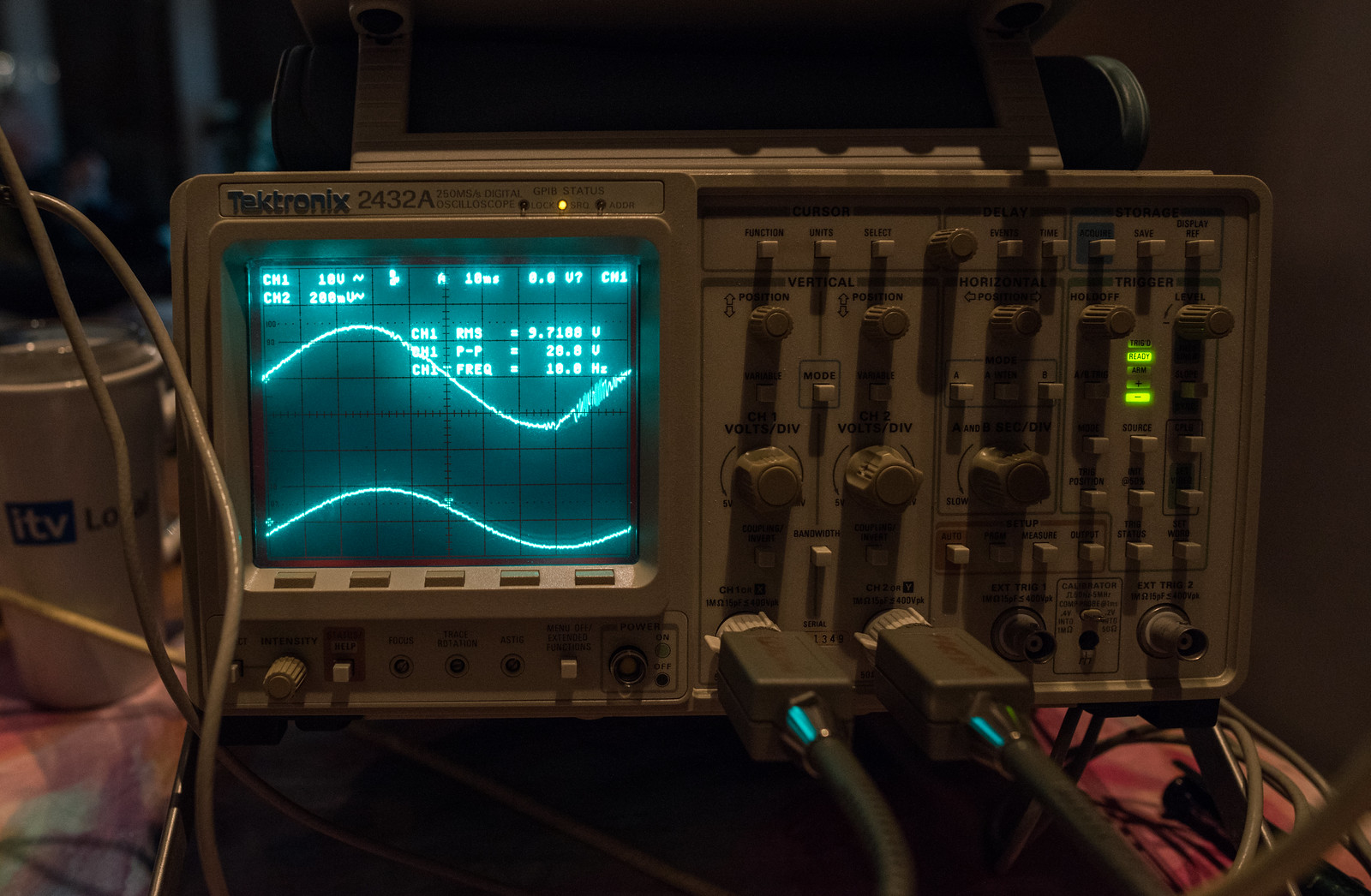
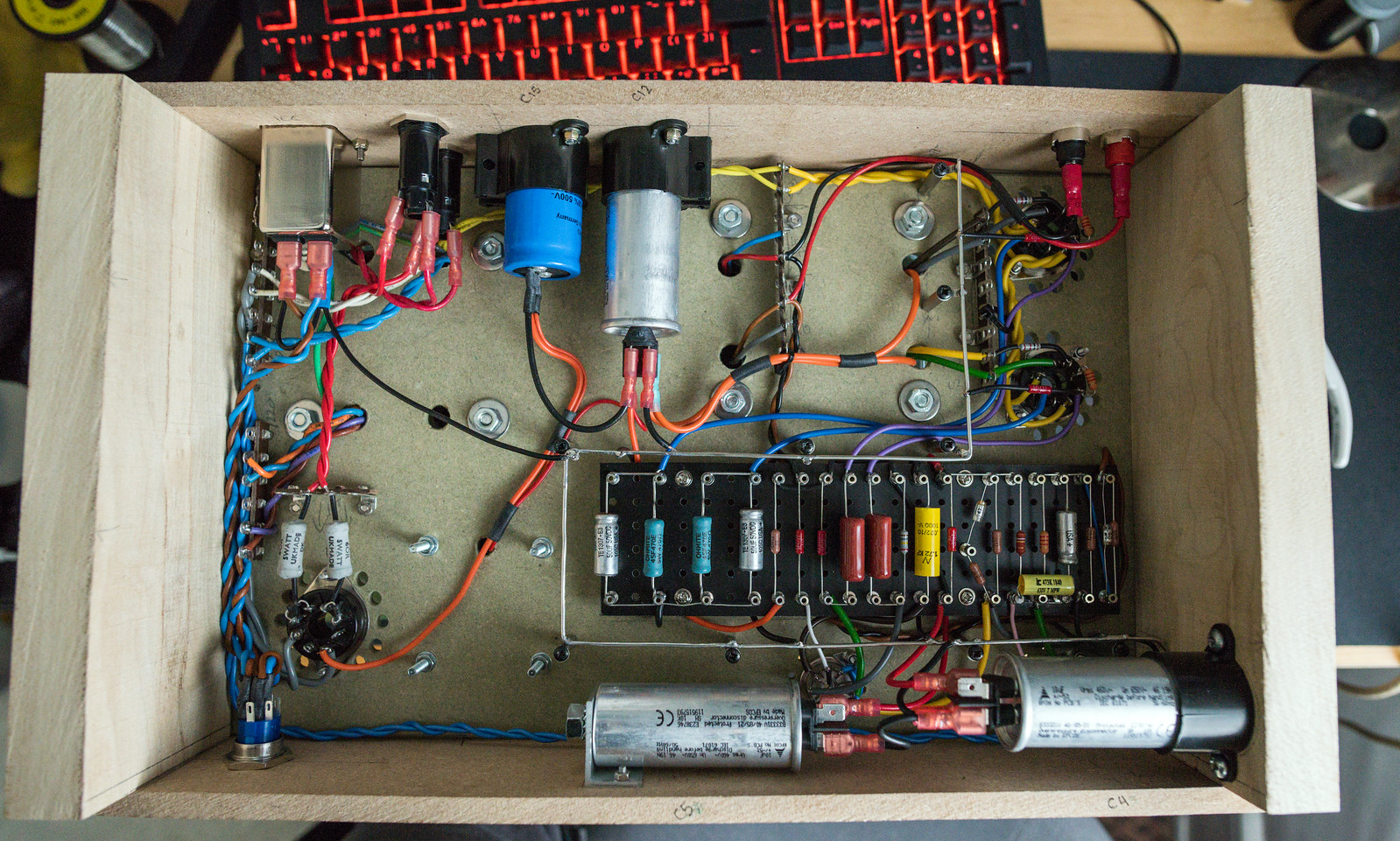
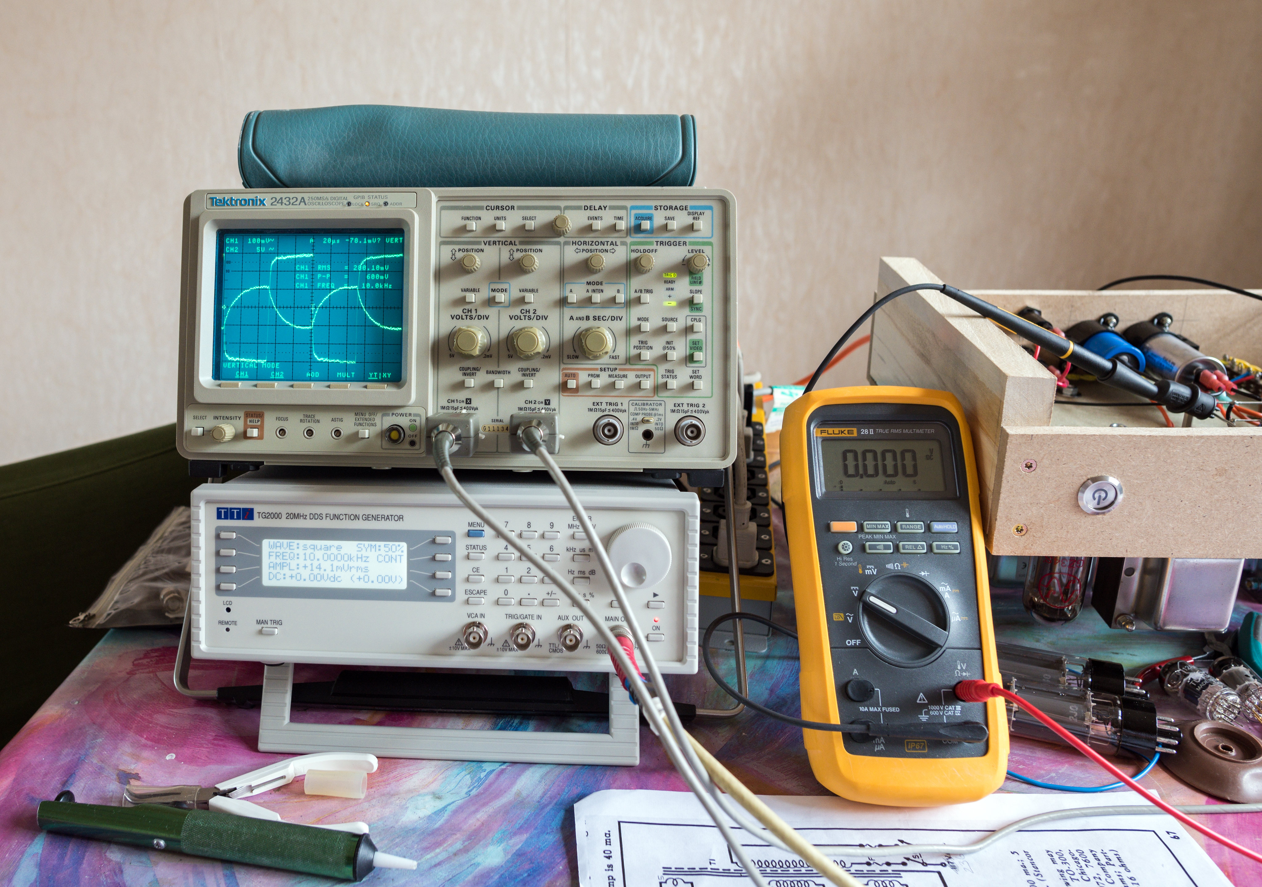
I've had some problems with rather excessive DC voltages which were causing excessive plate dissipation. (evident in the photos above as the orange glow to the grey metal of the plates in the EL34's) Checking the voltages, I was seeing around 20V more than I should have
I spent some time going over the datasheet for GZ34/5AR4 and realised that there is a minimum resistance per plate that I'd not realised would need to be checked.
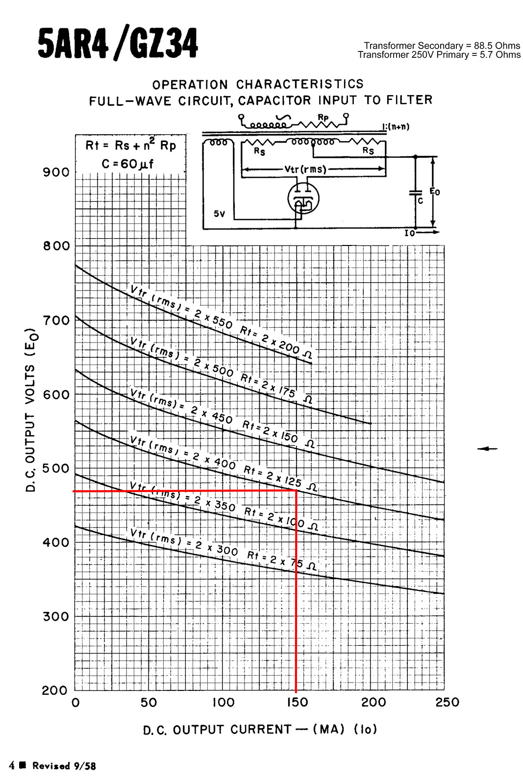
The valve wizard site also happened to have a handy formula for calculating it. (Rlim = Rsec + Rpri × (Vsec/Vpri)^2 + any extra resistance)
V Pri = 250
V Sec = 398
R Pri = 5.7
R Sec = 88.5
Result = 102.9464448
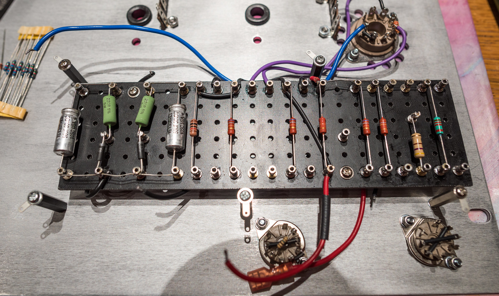
This put me a tad short of the 125 ohm minimum at 2x400V. (although they only list it for 60uF filter) I spent this morning having a good dig through my component stash and found a pair of 5W 60R vintage RS branded resistors which I've fitted in the 410-0-410 feeds from the HT fuses to the rectifier socket.

These are the measurements I got with these 60R limiting resistors in place. The numbers look significantly closer to the book figures now. I'm doing some testing this evening and will check with the camera to see if there is any sign of glow in the plates.
Mains voltage - 237.3Vac
HT voltage - 391Vac
C15 - 458Vdc
C12 - 441Vdc
C5 - 410Vdc
C4 - 165.5Vdc
V4 Anode - 431Vdc
V4 G1 - 0.7Vdc
V4 G2 - 433Vdc
V4 G3/Cathode - 30.9Vdc
Heater - 6.0Vac
V3 Anode - 431Vdc
V3 G1 - 0.6Vdc
V3 G2 - 432.5Vdc
V3 G3/Cathode - 30.4Vdc
Heater - 6.0Vac
V2 Anode 1 - 303.6Vdc
V2 Anode 2 - 303.7Vdc
V2 G1 - 88.4Vdc
V2 G2 - 80.4Vdc
V2 Cathode 1&2 - 92.8Vdc
V1 Anode - 88.8Vdc
V1 G1 - 0 (no signal)
V1 G2 - 110Vdc
V1 G3/Cathode - 2.1Vdc
Heater - 6.2Vac
The plates now look much healthier, though the camera can still see some infrared. I cannot see it with my own eyes in a pitch black room, so I think it's ok. Still sounds great and no audible noise that I can hear through the speaker although the mains transformer does hum slightly but it's not mechanically isolated from the whole assembly.


I spent some time going over the datasheet for GZ34/5AR4 and realised that there is a minimum resistance per plate that I'd not realised would need to be checked.

The valve wizard site also happened to have a handy formula for calculating it. (Rlim = Rsec + Rpri × (Vsec/Vpri)^2 + any extra resistance)
V Pri = 250
V Sec = 398
R Pri = 5.7
R Sec = 88.5
Result = 102.9464448
This put me a tad short of the 125 ohm minimum at 2x400V. (although they only list it for 60uF filter) I spent this morning having a good dig through my component stash and found a pair of 5W 60R vintage RS branded resistors which I've fitted in the 410-0-410 feeds from the HT fuses to the rectifier socket.

These are the measurements I got with these 60R limiting resistors in place. The numbers look significantly closer to the book figures now. I'm doing some testing this evening and will check with the camera to see if there is any sign of glow in the plates.
Mains voltage - 237.3Vac
HT voltage - 391Vac
C15 - 458Vdc
C12 - 441Vdc
C5 - 410Vdc
C4 - 165.5Vdc
V4 Anode - 431Vdc
V4 G1 - 0.7Vdc
V4 G2 - 433Vdc
V4 G3/Cathode - 30.9Vdc
Heater - 6.0Vac
V3 Anode - 431Vdc
V3 G1 - 0.6Vdc
V3 G2 - 432.5Vdc
V3 G3/Cathode - 30.4Vdc
Heater - 6.0Vac
V2 Anode 1 - 303.6Vdc
V2 Anode 2 - 303.7Vdc
V2 G1 - 88.4Vdc
V2 G2 - 80.4Vdc
V2 Cathode 1&2 - 92.8Vdc
V1 Anode - 88.8Vdc
V1 G1 - 0 (no signal)
V1 G2 - 110Vdc
V1 G3/Cathode - 2.1Vdc
Heater - 6.2Vac
The plates now look much healthier, though the camera can still see some infrared. I cannot see it with my own eyes in a pitch black room, so I think it's ok. Still sounds great and no audible noise that I can hear through the speaker although the mains transformer does hum slightly but it's not mechanically isolated from the whole assembly.


