You are using an out of date browser. It may not display this or other websites correctly.
You should upgrade or use an alternative browser.
You should upgrade or use an alternative browser.
System build guide
- Thread starter greywolf
- Start date
More options
Thread starter's postsAssociate
- Joined
- 4 Jan 2016
- Posts
- 2
I love this info
Step 7: Fitting the graphics card - Optional sound card
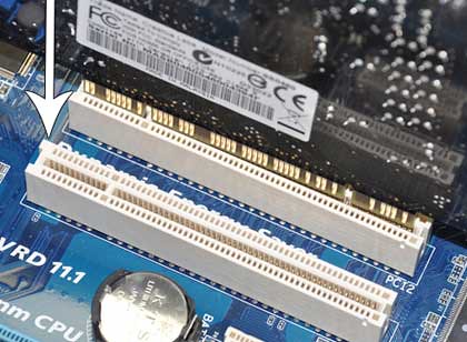
(A) Select the top compatible PCI-E 16x slot and remove the backing plate from the case for that slot so that access is available to the rear ports on the card. On most cases the plates unscrew or on cheaper cases they push out.
Once the plate is removed align the card with the slot and gently push the card down into the slot. The bracket on the card should now be inline with the case and be ready to be screwed down.
With the screw from the backing plate, screw the card into place.
Note: Most graphics cards require extra power to work, remember to attach the power to the card on the PSU connecting up step.
Note: Usually the PCI-E 16x has a catch on it which will need to be released if you want to remove the card.

(B) Optional sound card. Find out if the sound card is either PCI or PCI-e, and then select a compatible slot on the motherboard. Once a compatible slot has been selected remove the backing plate as was done with the graphics card.
Note: Some sound cards require extra power to work, if it does remember to attach the power to the card on the PSU connecting up step which will follow soon.
(C) Before the next step quick check is a good idea.
1. Motherboard fully screwed down?
2. PSU fully screwed in?
3. RAM seated in the slots correctly and clipped in?
4. Graphics and sound card seated in the slots correctly and screwed in?
5. Fans all connected? (apart from any 4 pin ones)
6. CPU cooler attached firmly?
7. CPU cooler fan plugged in?
8. Hard drive and CD/DVDRW drive screwed in?
9. CD/DVDRW drive plugged in at both ends?
10. Hard drive plugged in at both ends?
Step 8: Connecting up the power cables
(A) This step involves connecting up the power cables from the PSU to the required hardware. To do so push the power plugs over the sockets, they will only fit one way round due to the shaping on the socket.
When selecting a PSU for your build check to make sure that the PSU offers all of the power connectors required. As a substitute splitter cables can be purchased which connect to a 4 pin molex and so can give you either two molex or a range of other power connectors such as SATA. If possible try to get all the connectors needed hardwired or modular with the PSU.
Connect the 24 pin cable to the 24 pin slot on the motherboard which clips into place.

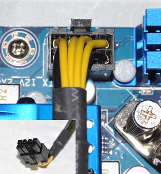
(B) Next connect the 8 pin cable to the motherboard which will clip into place. This is some times a 4 pin plug/socket or is absent.
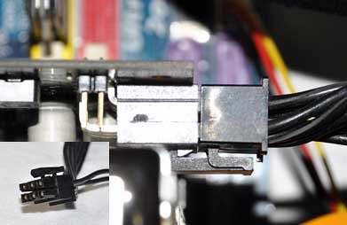
(C) Next connect a PCI-E 6 pin cable to the graphics card which will clip into place.
Note: Some graphics cards require two 6 pin PCI-E power cables.
Note: Some graphics cards require one or two 8 pin PCI-E power cables.
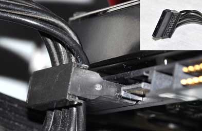
(D) Next connect a SATA power cable to the CD/DVDRW drive. Note: This is an L shape design, which only fits one way. Note: Some times a 4 pin molex is used.

(E) Next connect a SATA power plug to the hard drive.
(F) Lastly connect any 4 pin Molex fans via a 4 pin Molex cable. Note: If the fan is already connected to the motherboard via the 3 pin you will not need to connect it to the 4 pin Molex as well.
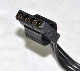
This is now all of the hardware fully connected to the PSU. Any unused cables from the PSU can be tucked away. This being a benefit of a modular PSU where only the required cables are connected to the PSU.
All that’s required now is to screw the side panels back onto the case and the systems is ready for an operating system to be installed. Remember to go into the bios and change the boot priority to the DVD drive first if the OS is being installed via DVD.
Associate
- Joined
- 22 Feb 2016
- Posts
- 2
Thanks, gret help, fantastic guide
Associate
- Joined
- 17 Mar 2017
- Posts
- 10
- Location
- Pakistan
Really good of you to make the effort. Naturally I'm posting to correct you, though I don't have much to take issue with at all 

Associate
- Joined
- 5 Nov 2018
- Posts
- 1
- Location
- 1948 College Avenue Dayton
Just wanted to say thanks for this information, it was really useful when I built my rig a few weeks ago.
Hi there
Briony from Kitguru has produced an excellent DIY for building your own PC, which happens to be all white themed as she does indeed love a white build.
Check out the full written review here:
https://www.kitguru.net/components/...hite-pc-in-the-limited-edition-dark-base-700/
Watch the YouTube video here:
Remember to give a thumbs up and subscribe to the Kitguru channel, you can find more videos here from Kitguru:
https://www.youtube.com/user/KitGuruTech/videos
And a video I help to make with Briony a few months ago:
Kitguru has fantastic content and their channel is well worth subscribing too.
Of course I love Briony but you could say I am maybe bias.

Thanks greywolf, great guide.
Gibbo, I like Kitguru along with Bit-tech.net and Hexus amongst others.
No problem Kitguru is my favourite for obvious reasons.

I want to build a good gaming PC for a long time. But at the same time I understand absolutely nothing about the compatibility of the components. I even thought of finding a specialist who can do everything for me, but I'm not sure that I will get exactly what I want. Thanks for the leadership, now I will try to do everything myself.
I'm looking at Intel Xeon processors, is it suitable for a gaming PC?
I'm looking at Intel Xeon processors, is it suitable for a gaming PC?
Soldato
- Joined
- 28 Dec 2017
- Posts
- 10,138
- Location
- Beds
In general, Xeon has higher core count and lower clock speeds than related chips. Newer ones are locked too I think so no overclocking.I want to build a good gaming PC for a long time. But at the same time I understand absolutely nothing about the compatibility of the components. I even thought of finding a specialist who can do everything for me, but I'm not sure that I will get exactly what I want. Thanks for the leadership, now I will try to do everything myself.
I'm looking at Intel Xeon processors, is it suitable for a gaming PC?
It's worth starting a thread here as you will get some interesting answers if you open up a discussion in its own place

Associate
- Joined
- 23 Jan 2021
- Posts
- 44
Useful stuff here
As a new member (but with enough knowledge I don't need this particular guide) I note that it is prominent but very outdated. Still a current version would be a great resource for new members / new to building their own PCs.
May I suggest that a 2022 version be made?
The problem with the existing thread is anyone clicking on it sees the OP and how old it is and will be discouraged.
May I suggest that a 2022 version be made?
The problem with the existing thread is anyone clicking on it sees the OP and how old it is and will be discouraged.
? What does that mean in English?Sie there are many factors for system guide and i understood your think but actually you need check results in google sir
Its always hard to maintain something like this. Even large youtubers (im referencing Linus for example) have stopped doing build guides, the tech changes so frequently, making part recommendations is basically useless as next week the meta has changed and your guide is old. Even smaller considerations, not just parts selection can make it difficult to keep something such as this guide always updated without someone dedicated to doing it for the newbies to use as a basis for their first build.As a new member (but with enough knowledge I don't need this particular guide) I note that it is prominent but very outdated. Still a current version would be a great resource for new members / new to building their own PCs.
May I suggest that a 2022 version be made?
The problem with the existing thread is anyone clicking on it sees the OP and how old it is and will be discouraged.


