The Big Shell Project

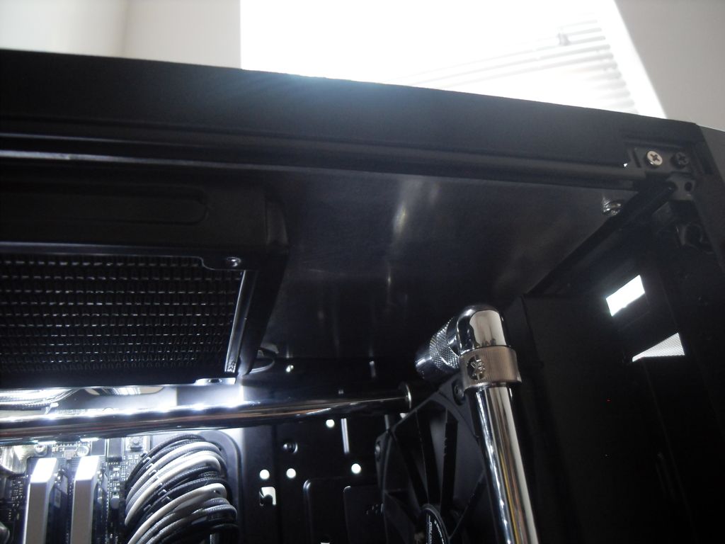
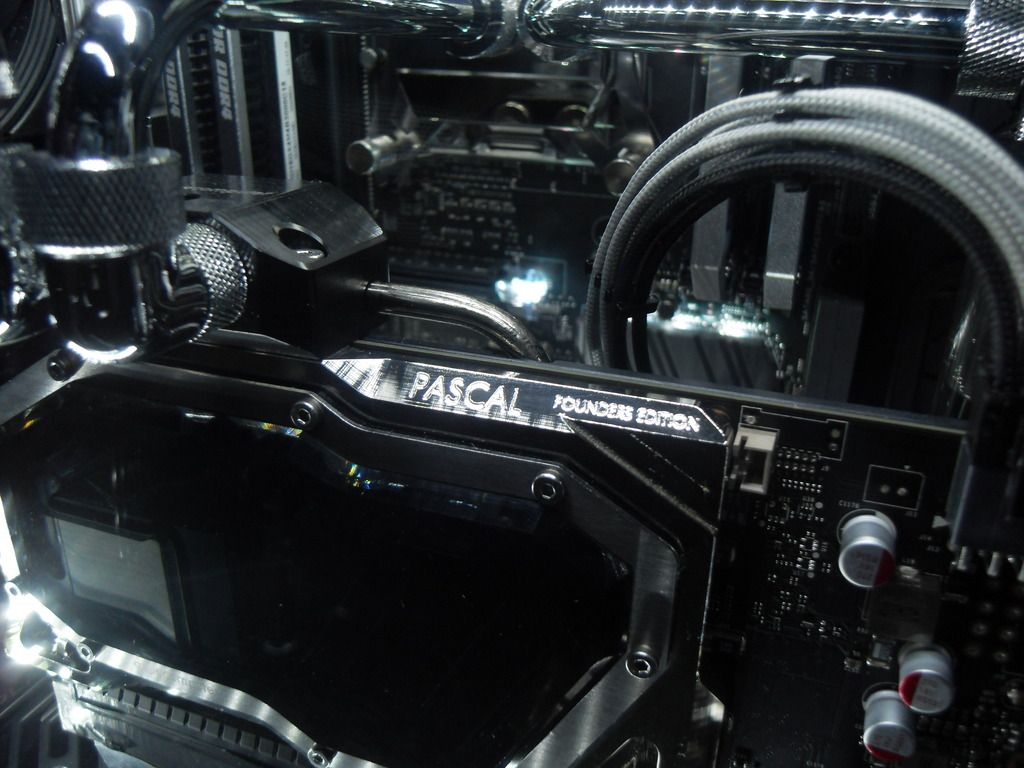
Here it is installed. The reason I'm probably not going to go through the process of removing it and polishing it to a complete shine is because it is such a minor part of the build now.

In my head this was going to be a gleaming beacon inside the case that would scatter light everywhere! In reality, it really doesn't show that much when installed and even sat at my desk you have to crane down to see it.

I do think it adds a nice look to the case though, definitely nicer than just seeing the fan bracket there! :cool:
SDC12680_zpsxztaok8m.jpg
 
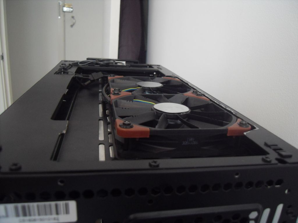
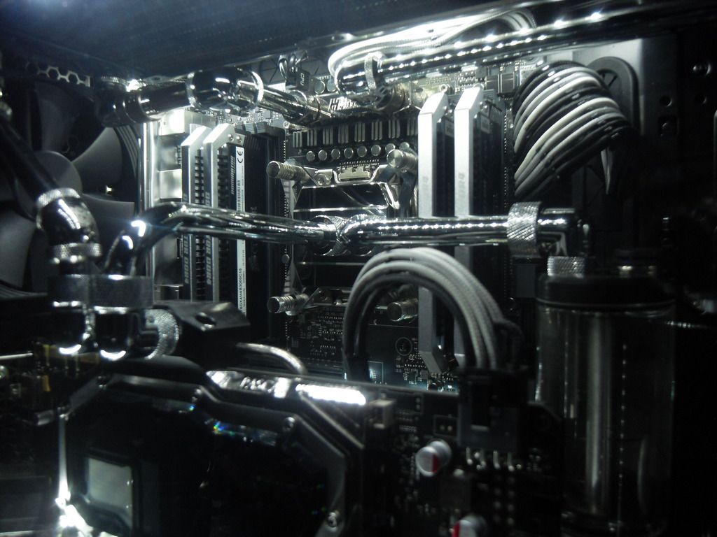
Little case mod update, the fans look like they will have plenty of clearance for airflow. There is around an inch of space integrated into the top panel which will be more than enough breathing room for the fans :)

SDC12677_zpsmgj7x8px.jpg
 
So all in all I'd say cutting out those top supports is a pretty useful mod to do.

The main gripe I have with the case is the lack of clearance at the top for radiator installation. If you want a radiator in the top of the case (pretty normal nowadays with AIOs) then it will start to significantly cover up your motherboard, which is only made more annoying by the fact that there is space in the top for the fans.

I feel Phanteks could have engineered the supports to sit above the fans, even if it would mean that only one or two positions of the fans would be possible without airflow being impeded.
 
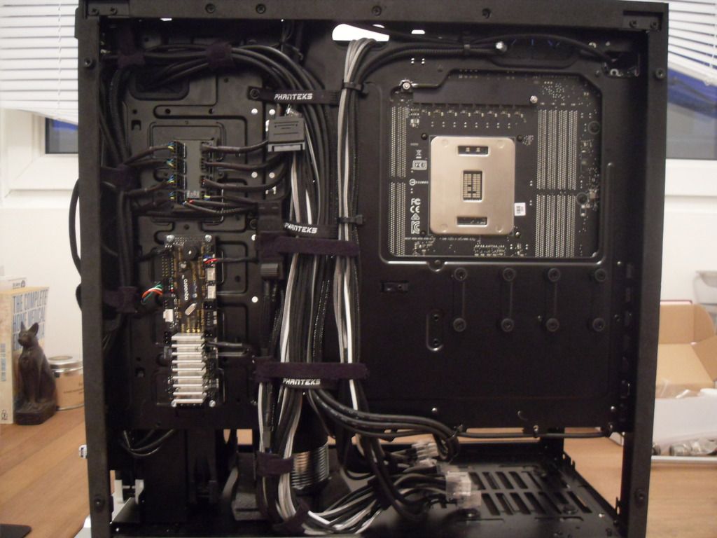
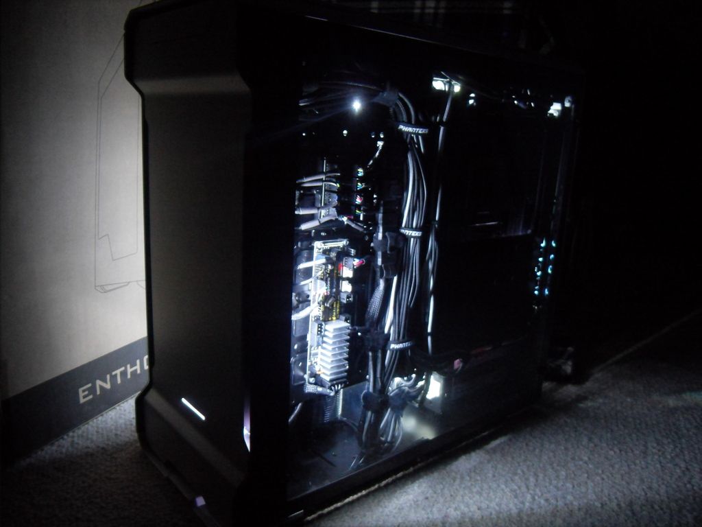
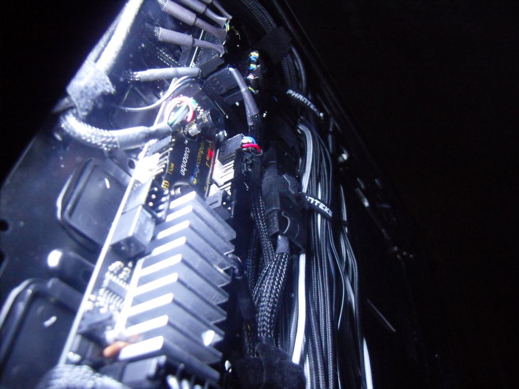
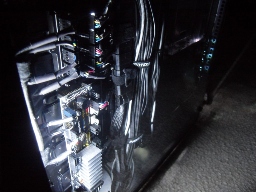
Brace yourself for the wiring updates. Most of the cables are done, all that is left now is the power for the Aquaero 5 and the LEDs.

The reason this has taken so long is because since both side panels are made of glass, I want the rear of the case to be spectacular just like the front. I'm going to have a small LED strip back there and as a result I'm making every cable myself so that they are all the perfect length. In total I think it has taken around 3 days of work (a good 6 hours-ish a day I think)... Worth it!

SDC12668_zpsd7sjmw1h.jpg
 
Given the density of cables I think that's remarkably neat!

Also just spotted your rotated graphics card. Would be interested to see how you've mounted it to the outside of the case.

The Evolve ATX does have a rather odd upper rad layout. I stuck the rad tray back in the box and sidestepped the whole issue ;) I'm surprised there's enough space to let the air in/out between your fans and the roof though - unless they've changed things between the ATX and the ATX Glass edition.

I'll get a picture and explain how the GPU is mounted this evening :)

There is around 2 cm of space between the fans and the roof, but the exhaust vents along the sides are also right there so it seems to vent quite well. And with the sheet of metal covering the bracket there is nowhere else for the air to go :P

I did a temp test yesterday of all of the panels (Side, front and top) on vs off and the coolant delta over the ambient air was only 0.5c higher at load which I think is explainable by the fact that the top rad is drawing air from the front rad rather than the outside when the panels are on and general heatsoke inside the case.
 
Now I've said it I think I'll do another test later to confirm it, sounds a bit unlikely to be that low so I'll do a more controlled test and post the results. But what I am fairly certain of is that if there is a difference it is not substantial by any means.
 
How the GPU is Mounted Vertically

I'm going to do a quick explanation of how my GPU is currently mounted and then I'm going to get on with some more updates, I know it's been a few days :)

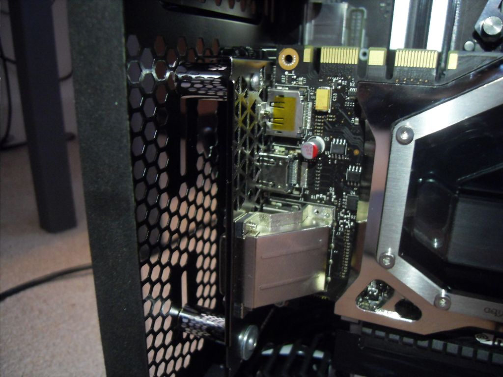
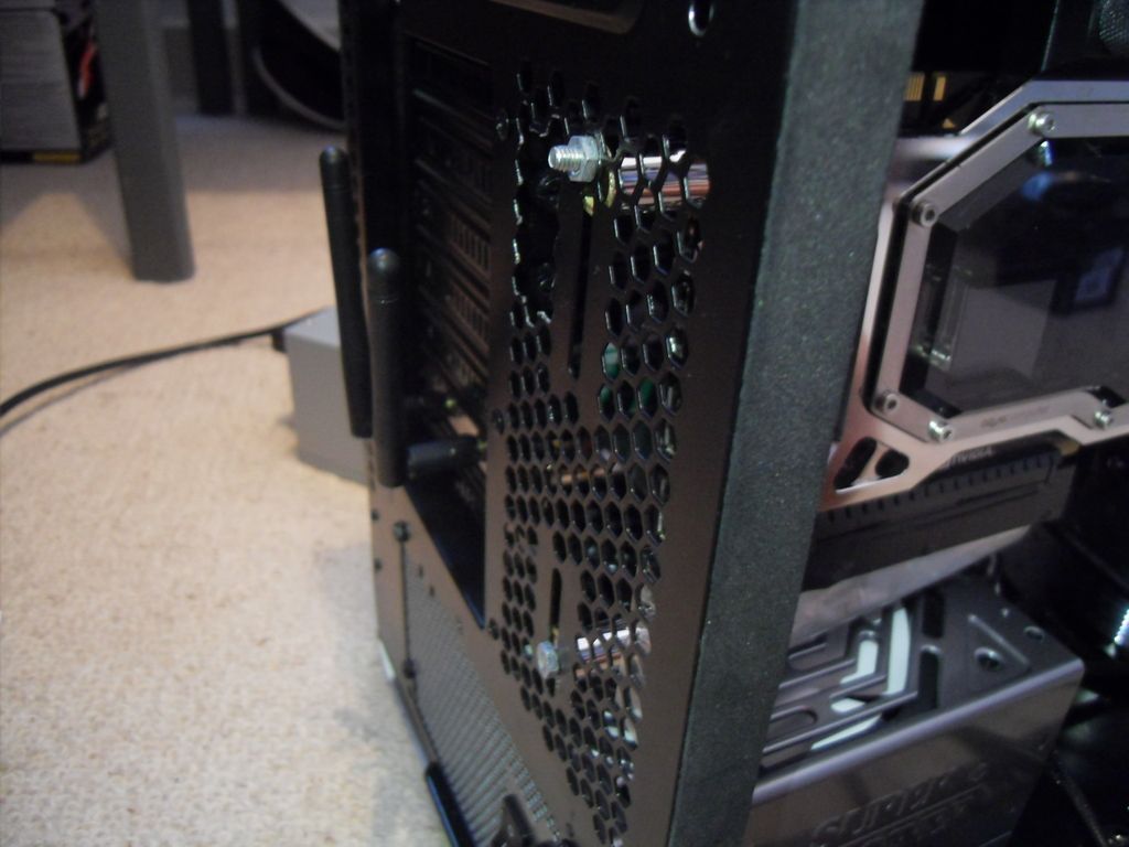
The pictures below show it quite easily, but basically I passed two long screws through the I/O plate of the GPU and out of the back of the case and then secured them with bolts.

Originally I had some random black plastic spaces I had lying around for some reason, but I swapped them out for some spare chrome pipe for aesthetics.

SDC12706_zpsm2b36w4o.jpg

SDC12709_zps3rr4yes3.jpg


The reason the top screw has be screwed in further is because that mesh panel on the back of the case flexes under the weight of the GPU, so to counteract the sag I used the screws to tilt it slightly until it was level inside the case.
 
Drain Port Installation

Normally in my builds I just run a T-fitting at the lowest point with a bit of extra hose and a ball valve at the end in order to drain the loop. It works extremely well and is pretty easy to do and use.

Unfortunately that wasn't really going to cut it for this build... I played with the idea of having a ball valve attached at some point in the loop, but no matter where it was, its large size made it look ridiculous.

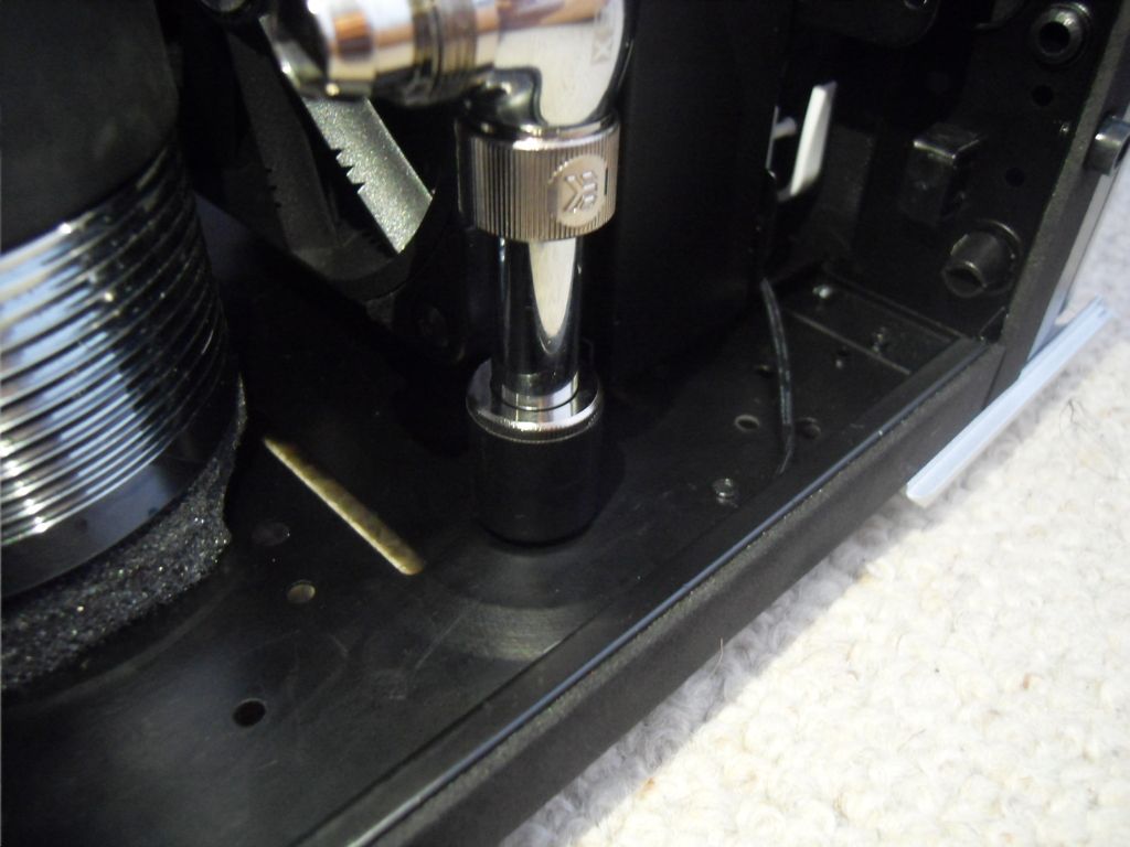
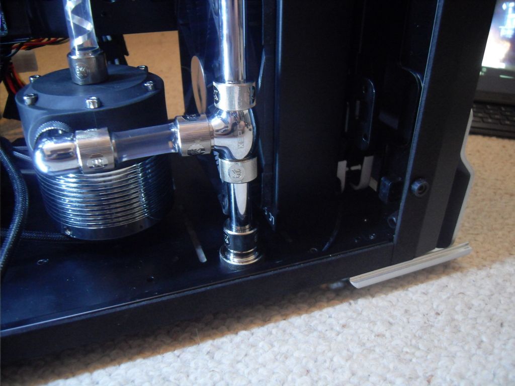
So I came up with the not so original idea of fitting a fill port to the bottom of the case for very effective draining (with it being the very bottom of the case) and I had a perfect place for it. Excellent! :D

Then I realised fill ports were just pass through fittings that costed more and used an 1/8" fitting on the outside rather than a 1/4" so I went with a pass through instead :p

First up, marking where I need the hole to go:
SDC12683_zpsnzana4nl.jpg


This was my ingenious plan. Stick some pipe and a fitting onto the end of the run that you want to line up and when that doesn't reach the base of the case stick some electrical tape around it so you can accurately mark which you want the hole to be.

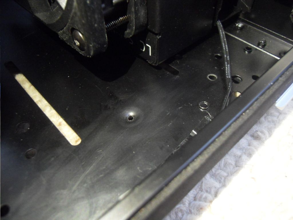
Then I punched a hole in the base to mark the centre of where I wanted the hole to be.
SDC12696_zpsxkpgkiga.jpg


Now I am going to have to apologise here. I have no shots of the in progress hole cutting. I drew a 2 cm wide circle around the pilot hole I made to accommodate the pass through. Then all I did was cut as large a square out of the centre of the circle I could with my dremel and then used the cylindrical grind stone fitting in it to refine that into a circular hole of the correct size :)

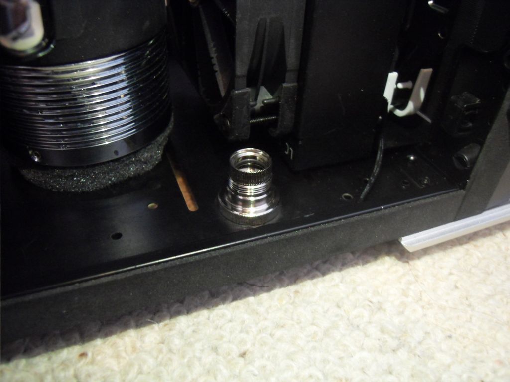
After a quick filing to smooth the freshly ground hole, the pass through fitting fit very snug!
SDC12698_zpsdiooxmqg.jpg


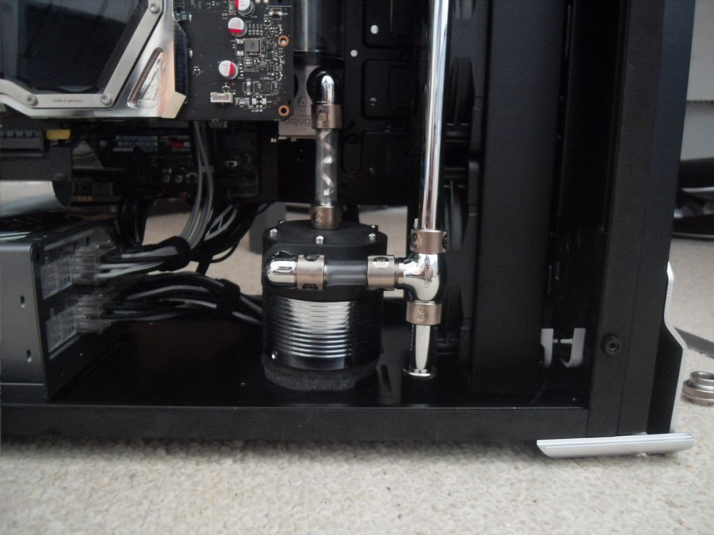
So, drain port successfully installed!

SDC12702_zpswhsl1qkb.jpg

SDC12695_zps6kln1xnc.jpg


I do really like the way the drain port turned out, it has definitely added something to the build.

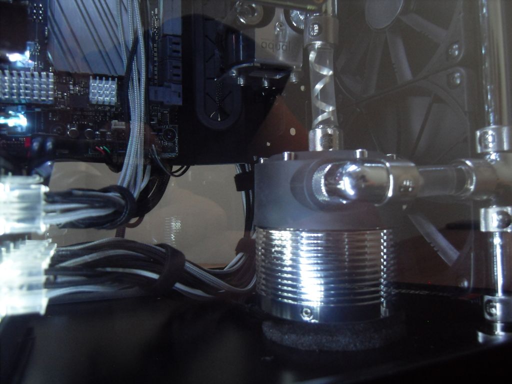
That is what the bottom right of the PC is like (Bit of a tease for tomorrow when the full glamour shots come in ;) ). The pump has soft tubing fitted to it to decouple it from the case, stopping it's vibrations from making additional noise. Who likes what I did with the silver kill coil in the soft tubing? I might get another for the other bit of tubing :p
 
Ahh okay, I don't intend for anything other than 1 DP to go in.

The end of the kill coil is hooked over barb of the compression fitting and isn't going anywhere. Even before the fitting was on I couldn't shake it out of the tube and now it is hooked on the only way it is moving is if it breaks, but that would be a problem even if it was in the res.
 
Sideways gpu fitting makes sense now. Don't think it'd work for me though as I'd have to cut too many slots in the back (2xDP, 1xDVI). I do like how it presents the 'show-side' of the GPU and I doubt you spend much time looking at the back!

You should check out the racing rig that OC3D have just done. It has a bit more practical/far less ghetto of a mounting system than mine. I needed the GPU to be further out and across though.
 
It has been far too long! The weeks just sort of rolled by without me noticing and I also had to put the finishing touches of the build off until I had more time that I could set aside for it.

However, literally all the waiting is over. It is built. It is polished. It is overclocked. It is 100% complete and setup!

Prepare for the updates to roll out :cool:
 
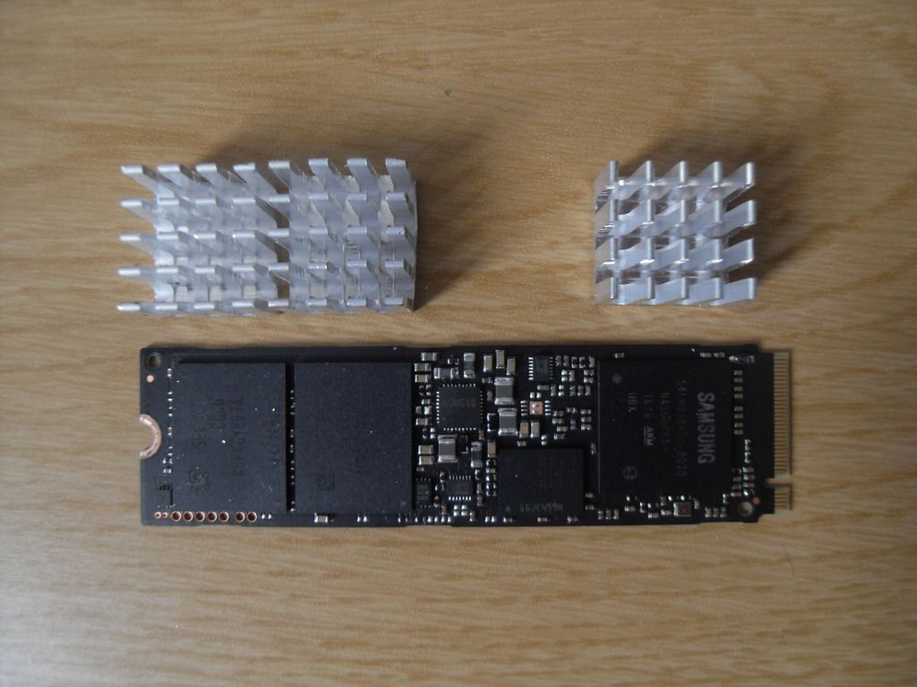
Putting Heatsinks on the SSD

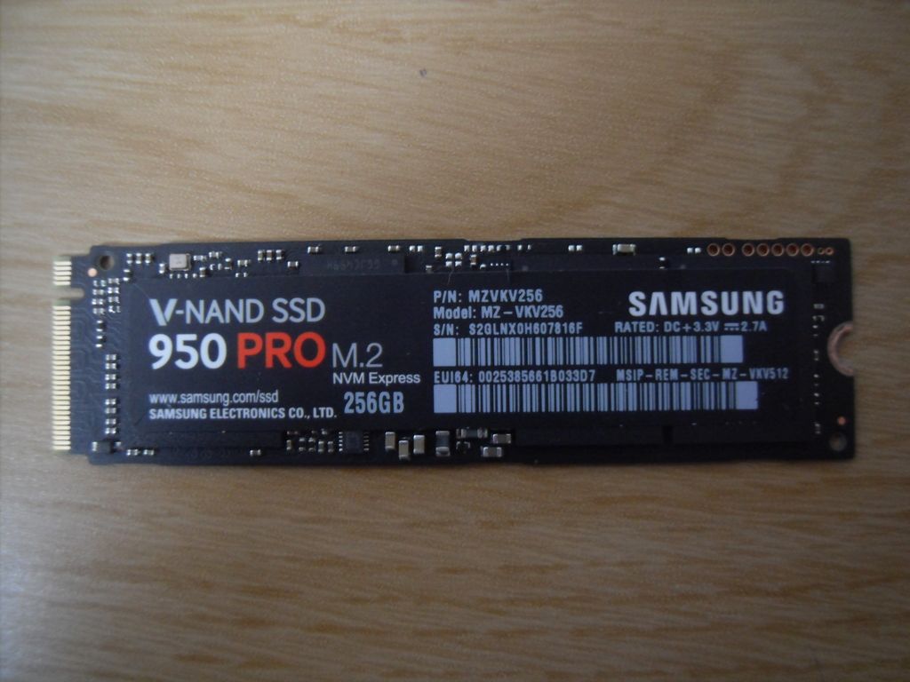
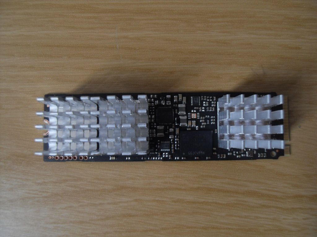
Yeah okay, that previous post was a bit misleading considering this update I guess. Basically, I put heatsinks on my 950 Pro, I have pictures of it and I figured someone might want to also do it so I might as well log it.

The idea came form hearing that under certain loads the 950 Pro can thermal throttle and that applying small heatsinks to the flash and controller chips solves the problem. Now, my SSD will never undergo these certain loads, it just isn't part of my day to day activities, but I simply could not pass up an opportunity to add more luscious metal to the build under the pretence of practicality ;)

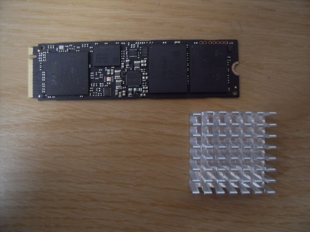
Items required: Heatsinks, adhesive thermal pads, a hacksaw and a file (if you heatsinks are too big).

SDC12811_zpsg9my1kr5.jpg


First step is to peel off the sticker. It comes off really easy, it is not stuck very strong at all.

Next, measure up the heatsinks to cut them to size. I bought slightly large ones for versatility in other projects

SDC12814_zpsx1qhffxg.jpg

SDC12815_zpsj9heprkl.jpg


I got a 10cm x 10cm x 0.5mm adhesive thermal pad off of eBay that worked very well (so far at least...). I cut pieces that covered the bottom of the heatsinks (so none would poke out of the sides) and cleaned the surfaces of the chips and the heatsinks with alcohol before sticking them on.

SDC12817_zpsitab65bc.jpg


Next come actual finished build pictures, I promise!
 
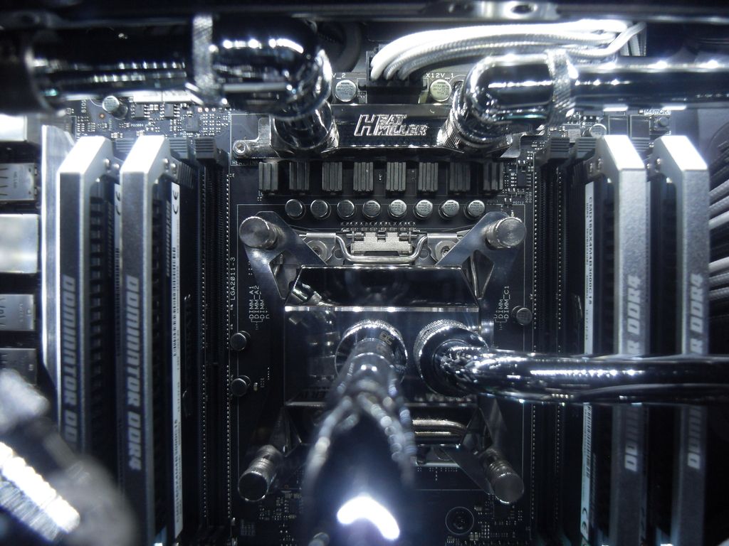
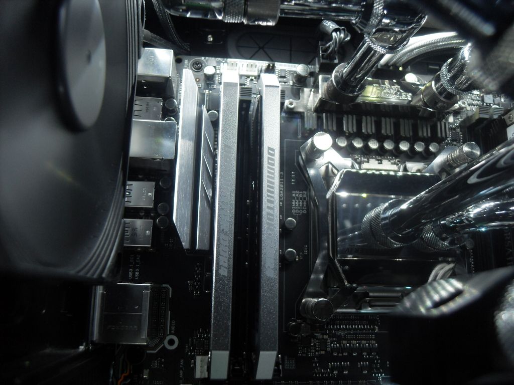
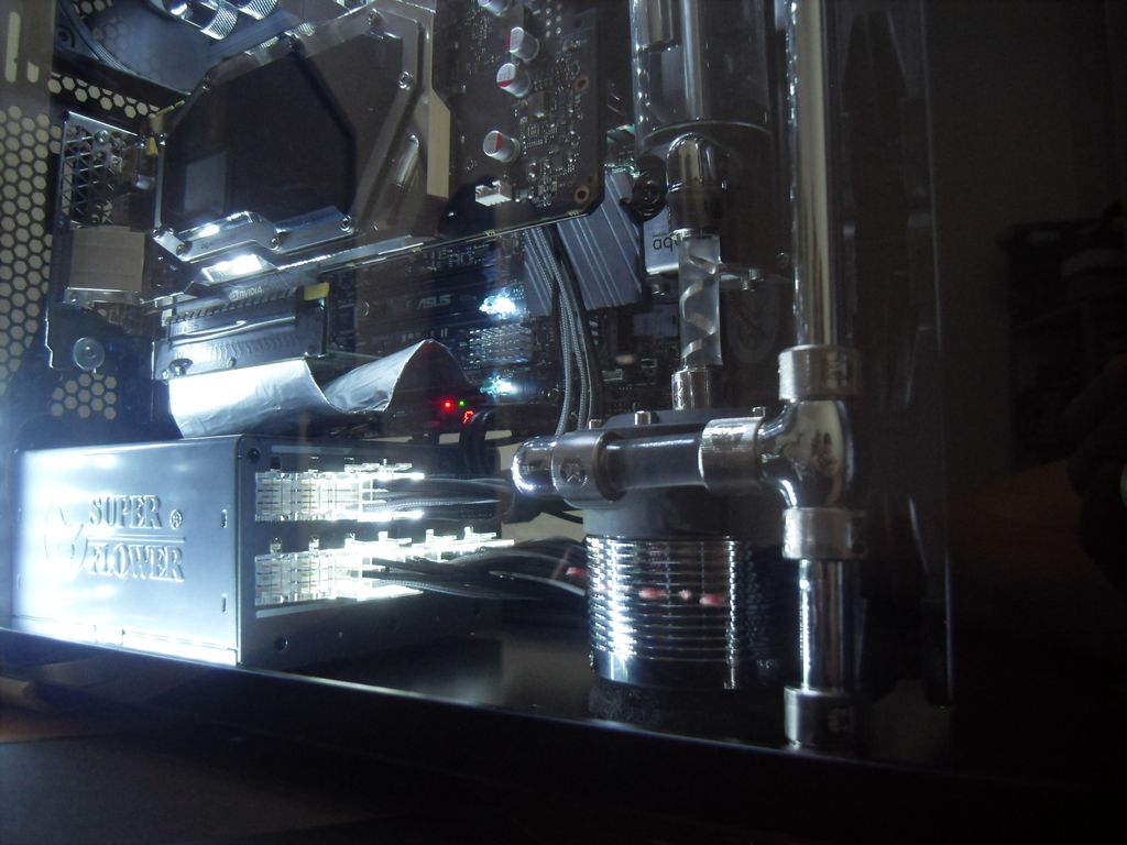
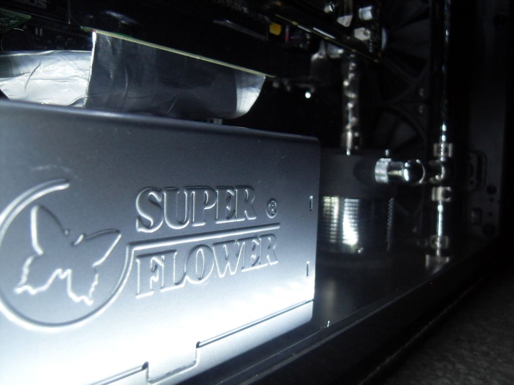
The First Sexy Shots Are Finally HERE!

I apologise if you were hoping my camera game is strong. I have an old camera that was reasonably inexpensive at the time and my artistic skill is negligible. I did my best, and I am proud of some of these shots, but others aren't fantastic and are included just so you can see that part of the build.

1_zpsbopvboxz.jpg

2_zpst9mxq8ci.jpg

3_zpsujekmtyt.jpg

3%202_zpsobzv8owp.jpg
 
Overclocking the CPU

DW, more pictures coming this evening :)

There is a TL;DR at the bottom if you are only interested in the results.

I couldn't get 4.5GHz stable at anything lower than 1.28v despite my efforts with DIGI+ and what not, which as far as I'm aware makes this chip somewhat mid-range (1.25v-1.30v). But, since lower clock voltages aren't necessarily indicative of higher clock potential I started the higher voltage adventure towards 5GHz! (Spoiler, it didn't make it that far :p )

I started with trying 4.7 at 1.35v, leading to a very quick failure. 1.38v got it stable at 4.7 which enthused me, but at the same time made it clear that this adventure wasn't going to go very far. So I had to move into the no-man's land of 1.4v+ to get any higher clocks and managed 4.8GHz stable at 1.46v (no-intention whatsoever of keeping these OCs here, this is solely out of interest).

Not being willing to go much further than this meant the quest for 5GHz was obviously lost, but 4.8 stable isn't bad and 4.5 at 1.28v is nice for a 24/7 :) I tried getting 4.6 at around 1.3v, but that didn't even get through post haha!

TL;DR 4.5GHz on the 5820k at 1.28v adaptive without touching any settings like LLC and stuff and maxed out at 4.8GHz at 1.46v.
 
Overclocking the GPU

I'll be doing benchmarking soon (hopefully will be running the tests tomorrow) in Firestrike and games at 1080p, 1440p and 4k.

There is a TL;DR at the bottom again if you don't care about reading an overclocking adventure featuring GPU Boost 3.0 :P

With all the Pascal overclocking hype, the worry over power delivery and all the AIB partners going ridiculously over the top with power and voltage I was so excited to get overclocking and was determined to hit 2100MHz.

With power target and temp limit maxed I started off with a core offset of 200MHz.
Stable, clocking in at around 2076MHz I think. So that was easy. No extra voltage, just moved three sliders.

Next I tried a core offset of 225MHz and it started artefacting in Shadow of Mordor (around 2114MHz). Uh oh. I furiously started adding voltage, but instead of stabilising to start with it kept the artefacts but upped the core clock to 2126MHz. When I maxed out the voltage slider it stayed stable at 2126MHz! :D

After some fine tuning I found that with a core offset of 214 it will hit 2114MHz with 100% extra voltage in Afterburner, 2101MHz with +25% voltage and 2088MHz at stock voltage (actually stock, not like Precision X stock that automatically has +25%). All of these profiles were also stable with a +500MHz memory clock.

I decided to leave it on the stock voltage profile that hit 2088MHz because the difference is 1-2% and it does hit 2101MHz and 2114MHz under certain loads that for some reason don't require much voltage. :cool:

The limiting factor here was sometimes power (in Witcher 3 particularly) and sometimes voltage, though I was getting artefacting when I tried to push it any further rather than power and voltage limits so I think I am getting the most performance my chip can give.

TL;DR It can go as higher as 2126MHz, but I will be running at 2088MHz at stock voltage with a +500MHz to the memory clock :)
 
Back
Top Bottom