Vince's Repair Thread - (Console Repairs & Mods)

Heres a pic it looks terrible and i had no flux so just soldered without a scope as well so just by eye

https://postimg.cc/kV6j7xVx
20220221-205819.jpg

kV6j7xVx

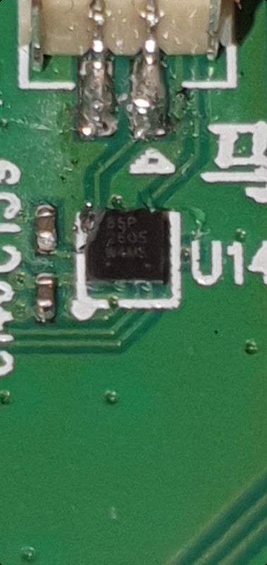
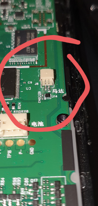
Does it work? The connector itself looks OK to be honest, that chip below it looks like it may have taken some surface damage though.
 
The switch was off a customer never got back to me

I have a load of laptop motherboards if you want them for a tinker with

You and me both on the laptop board front. To be honest though the laptops haven't been something I've busted out yet, having far too much fun on the console front.
 
No, i still cannot get it to connect no matter what i do, yea when zoom into the picture it does look like i may have hit that chip below it

You could test the chip, get its pinout and see what it does.

What markings does it have on top of the chip?
 
I have nothing to test it plus i wouldnt know where to start, Ive defo hit it from these pics my own daft fault rushing into something i have no idea about

Screenshot-20220221-214447-Gallery.jpg


Screenshot-20220221-214409-Gallery.jpg

Let me do some digging looks like a 9 ball bga, could be an IC that deals with battery charge levels or similar.

If we can find the chip I'll happily swap it over for you. Its hard to properly see the markings looks like 85P 2605 W4MS possibly.

Edit: what's the exact model of the remote?
 
Last edited:
Yea that is the numbers on the top, its A harmony elite remote or a Harmony 950 both considered the same

I'm not sure if the part number should be 260S its a bit hard to tell. Either way I haven't been able to find out what the chip is. Google hasn't been kind.
 
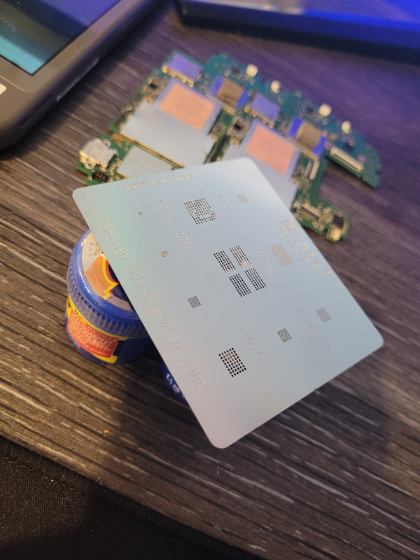
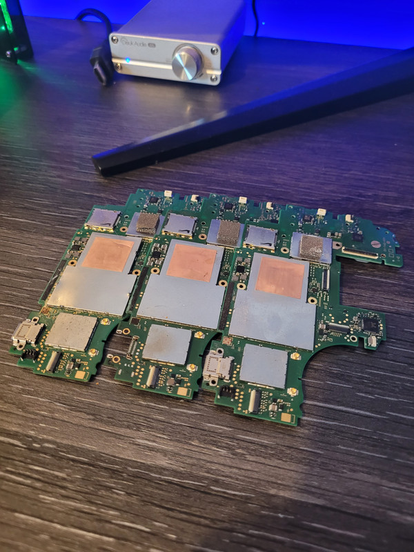
Well pink switch has a faulty Max77812 and you guessed it there are none of that chip anywhere apart from china... So I have ordered from China but have also ordered up a switch reball template which includes this chip... Looks like I shall be stealing it from one of my donors and reballing it onto the pink one.
 
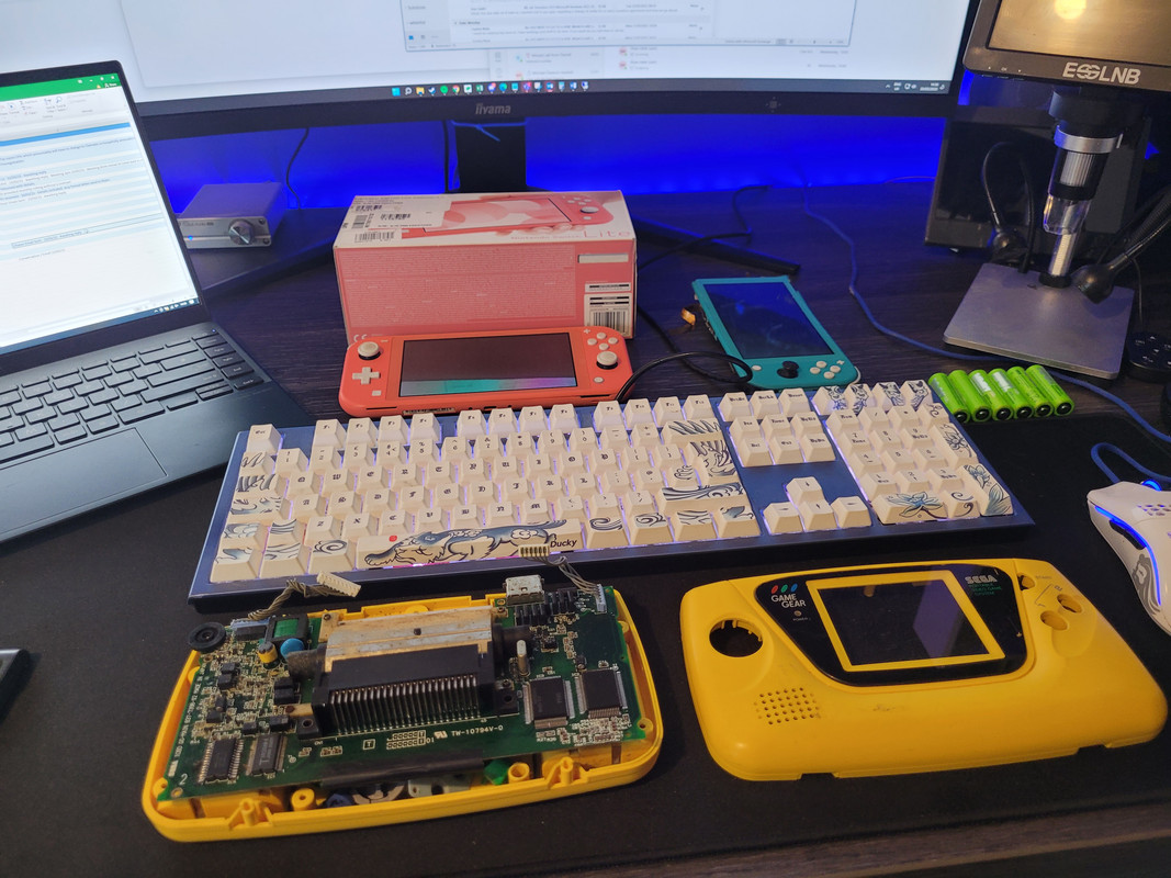
The yellow GG is another one with Trace/Asic damage - Figures to be honest as half the twin Asic ones I have seen need a lot more work. First off it was one of those ones that like to turn on and straight off. Worked out that the 35v rail was pulling 5v low so given the fact the screen was smashed anyway I went ahead and removed the 35v circuitry. Ive now got the GG to red light stable boot and have managed to stabilise the 5v rail. This is good!

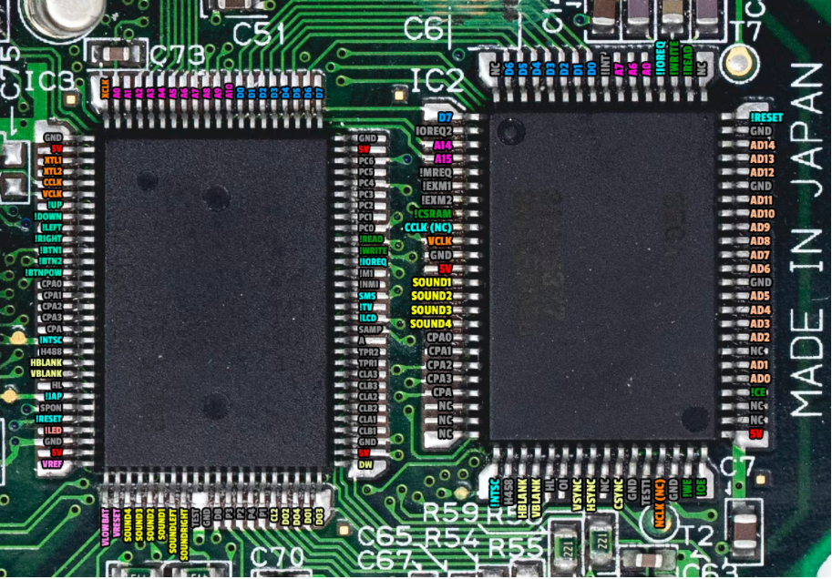
Next up I decided to check pre game ASIC operation, when you turn a GG on it should produce 3 signals without a game inserted, you should see VSYNC, HSYNC and CLK signals so last night I finally got the scope installed and started probing the board to see where we are at in terms of ASIC operation...

What a valid VSYNC data signal looks like:
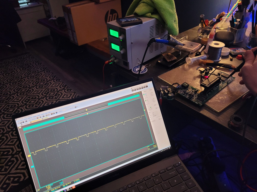

This is HSYNC:
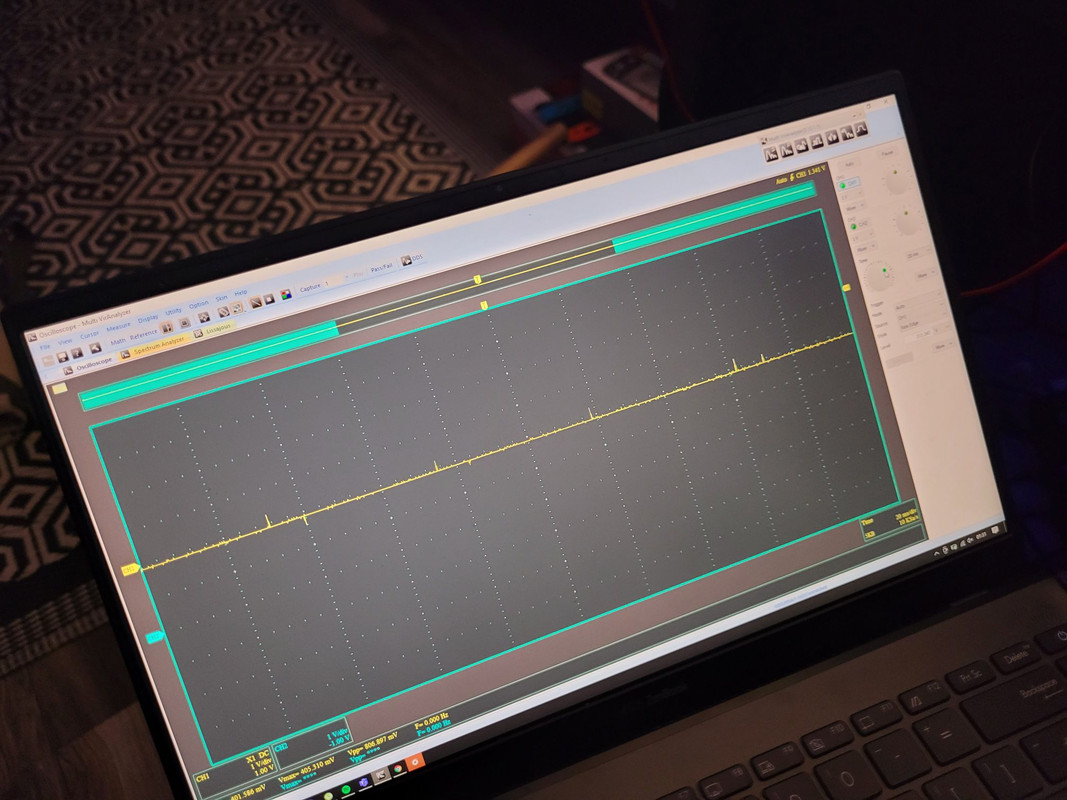

And our 3mhz clock signal:


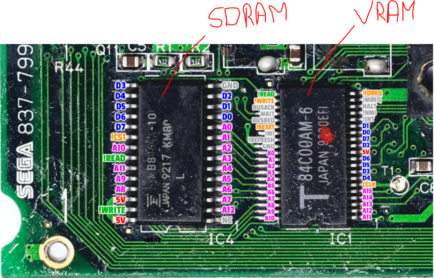
With all of these valid signals being pumped out by ASIC B we can be pretty sure that this ASIC is functioning, next up I checked from the cart slot to VRAM and SDRAM on all other data lines D0 through D12 (Not the read lines etc just the data lines) and noticed that we have an issue with both D1 and D0 data lines between the VRAM and SDRAM, all other data lines we are seeing clean signals, basically we have a rusted out VIA so will need to run some Jumpers on the two data lines where we have a load of resistance that shouldn't be there. Being an early Japanese revision board there isn't a whole load of documentation but its super similar in terms of layout to early revision EU boards so im sort of using them as a baseline.

Next up I need to check all lines from the cart slot to SD/VRAM back to the ASICS so that is where I will focus next. Once we have all the core data lines up I should then be able to test a bit further but having removed all of the 35v circuitry I will need to do a screen mod on it anyway and that will take its time to come in from china... Still I am going to get the board working, reading carts etc before that comes in.

I also plan on probing the GG I broke to see where it all went wrong so will update this thread with details of that investigation as well, mind you I will need to recap it again as I removed them all when my other donors came in for mine and nutritions GG's last week. But yea the "silly" scope is super useful for these kind of repairs.
 
Love this thread, it's like stuff I wish I could do but also have no intention of learning to do.

Well you are still coming along on the adventure and we are learning as we go - I'm by no means an expert or anything so for me a lot of this is kind of me teaching myself how it all works. It's fun but challenging at times.
 
I’m far from an expert lol more like a try and hope for best and pick up knowledge as I go :)

Ah man you need a scope like this in your life. Honestly I found it for 50 on ebay and now I think I have 99% of what I need for proper in depth dives into stuff. Without some sort of scope on data lines it's almost impossible to tell if something is working exactly like it should. Now though I can say with complete certainty that's asic b on this board is fully functioning.
 
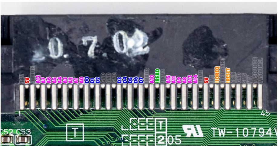
I've spent now hours testing the game gear and have fixed some data lines one with a jumper and another by bending a pin in the cart slot. It's really interesting using the scope for this as I can see the signals being generated out of the cart and as I trace those signals back through the cart slot then to ram/vram I can see exactly where the signal breaks. It's a long and tedious process but I am getting there. Basically the process goes something like this, this is the GG cart slot pinout:


You trace every pin from there and test to every pin back to the asics and the vram... you can see how this might take a while...


I've taken a break because I have come across another broken address line at the cart slot (A15).
 
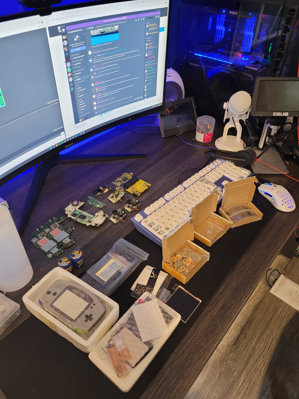
Fairly massive china order just landed - Watch this space for some retro goodness!!! Yea baby!!

We have in todays fun

1 - IPS kit and case for GBA
2 - IPS kit and case for GB Pocket
3 - Pots for switch pro controller
4 - vita charge port
5 - 10 switch charge ports
6 - BGA solder paste

Its a fairly big haul


Still waiting on around £400 worth of stuff from china for more projects!!
 
Last edited:
gotta love nice big deliverys! Looks like a lot of fun to come :)

A lot of fun has already been had


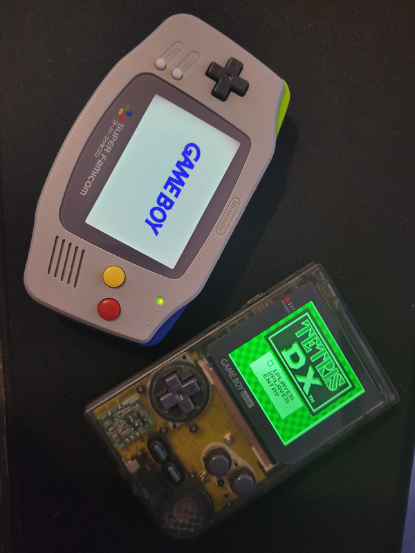
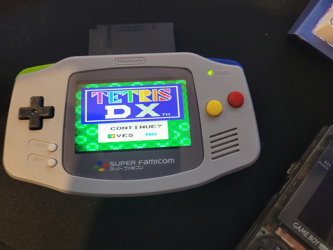
That was my GBA board and the pocket... both reshelled and looking damn good.

Tonight we are reballing max chips...


Then I am going to fix the 4 switch lite boards in my queue. Or I might do the Vita port... Or the Switch Pro controllers new pots... the options are endless...

I do still need to do more probing on the yellow GG as well! Basically I have a ton of stuff to work on!

Either way the pocket is getting listed straight away as I dont really want it, I just wanted to refurb it.
 
Last edited:
Today we can tick a few off of the list the Mrs was out for the day so I was happily in my own little world repairing and playing with stuff for a lot of the day. I decided to get a start on some of my switch lite boards. I regret that decision...


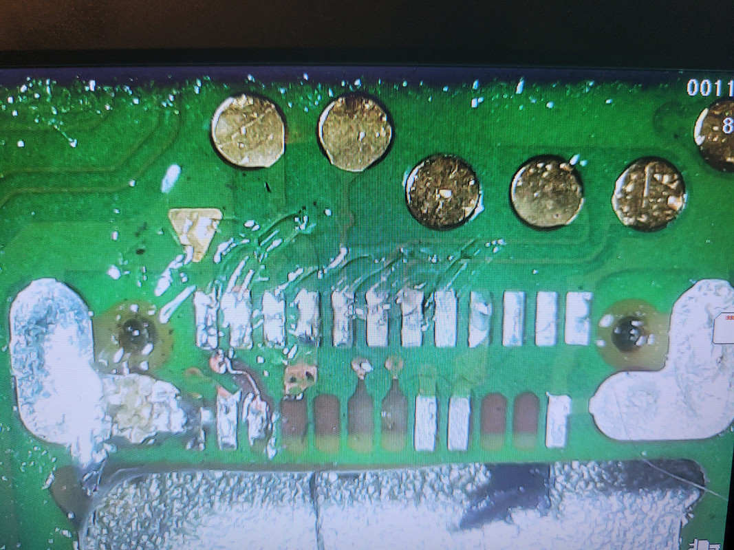
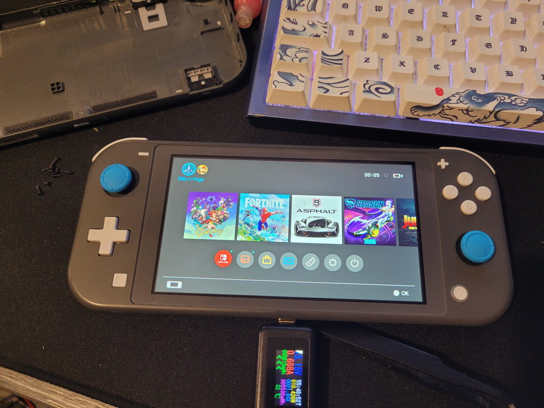
Board number one somebody has tried to replace the port and ripped all the hidden pins like a hooligan so here I was replacing traces with tiny trace repair things.. I only took a picture of the first one, second pin across on the bottom "hidden" row. But I replaced every required pin and trace, as well as m92...


Then I stuck some blue analogue sticks in it, because why not.

 
Looks like I may be joining you on my first GG, one on route , powers on but green screen / no video. See what I can do, may have to get a scope :)

New toy, reads as stopped reading games then stopped powering on , goddamn it’s yellow!

08144-CBF-C68-A-41-CE-9-F84-2-AB01-E3959-DA.jpg

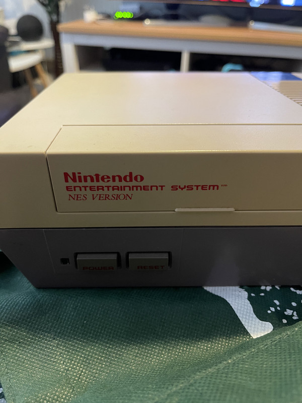
Ohh a NES! Look at us going all retro! - Cant believe that LYNX I paid more than I wanted but look at the condition!!! That NES looks pretty nice condition bar the yellow.

I fixed a the really bad green switch today using voltage injection! got loads of pics but ive replaced 5 caps and a fuse so far and have managed to remove a short from the VSYS rail... I think it might work when I put the component back on now!!! Also I reballed my first BGA chip successfully today... I also have pics of that :D - So much cool stuff to share!
 
Back
Top Bottom