Component level board repair. Watch me fail here!

sent you a trust can you fire me your address over and I'll post it over.

Done my details have been sent to you. I should probably send you my phone number as well! I'll do that a bit later on today. Should be interesting to see if it is what I think it might be. I've seen a lot of 7970, 280 and 280x cards over the years so am quite familiar with them!
 
@Vince Is this you: https://www.youtube.com/user/mymatevince/videos ? ;)

Bit of a coincidence though.

That is not me. Not many fellas called Vince out there though so yes a bit of a coincidence that one! My youtube channel is simply me showing bits that I did to the 911 so a walk around after the respray, a look at the exhaust I had made for it, the setup of a mirrored custom head unit, that sort of stuff really :)
 
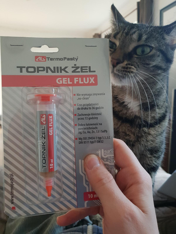
This arrived:


Weirdly I have 3 cats and the only one that's been interested so far is tabby cat (solder cat), who knows as we go through the others might peak an interest as well :) All i'm waiting on now is the tweezers and lets be honest this is probably one of the most important pieces for these little projects.
 
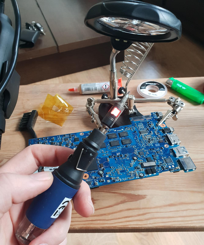
I spent a little bit of time earlier messing around with my test board:


My initial thoughts are that the magnifying glass is useless for working with but fine for checking how you are getting on between doing little bits. My soldering iron is too fine for cleanup using wick, so I need an iron with a flat rather than a pointy tip. When I took the bga chip off it came off really clean and with a pair of tweezers rather than the little screwdriver that i used to take them off I wouldn't have knocked off a tiny resistor above the chip.

The hot air station thing is actually pretty good, I was messing around with the air speed and working out the melting points of the solder on this board and it seems to do a good enough job for what I need to do for now. I'm sure if I used a much better one Id notice all the differences but for me right now it seems to be fine, It blows hot air out up to 450 degrees and really that's all you need. On this Samsung board I was up at about 390 degrees with a slow air speed of around 3 for a few minutes in the area of the bga chip with tape all around it holding everything else in place and that seemed to work.

I was trying to get every last bit of solder off of the area where the chip was sitting with the iron and a wick and knocked off one of the pads where the bga should be seated, I was kinda testing the process before i start the phone so now i'm thinking that I might need another solding iron as well. something a bit bigger but still cheap. The other option is find another head for my current iron.

Final observation, today i was testing using the liquid flux and to be honest it seems to dissipate really quickly and i didn't really get the impression it was helping me all that much. I'll move onto some of the gel stuff tomorrow or when them tweezers turn up to have a little go with that and see how it feels.
 
Loved through board soldering for the past 25 years but I absolutely detest doing any surface mount stuff, especially as I get older and my eyes get worse, but if you can do it then it's a great skill to have.

PS +1 on Louis Rossman too!
 
is a 15w 4mm tip soldering iron ok for doing stuff like above?

https://www.biltema.se/en-se/tools/soldering/soldering-pens/soldering-set-15-w-2000019024

that for example....

Doesn't say much about it lol

I'd highly recommend getting a 40-50watt temperature controlled workstation even one of the more reasonable priced generic brands if you are going to be doing much soldering.

I use 0.5mm and 1mm tips a lot and occasionally one of the bigger tips usually at an angle or the reverse of the very tip.
 
Get yourself a TS100 soldering Iron for £50 it's well reviewed in the electronics community and is comparable to £200+ Weller and Haako Irons


That's what I use, though I do have a selection of tips for it which soon bump up the price of the setup. You also need something to stand it in, so another few quid there, and they don't come with a PSU either. Fortunately I run mine off my bench supply.

Ok I'll rephrase it.

Can that what I've linked, is it good enough to unsolder and resolder a bios chip on a motherboard.

That's a bit like asking is X camera good enough for winning a photography competition. How you use the kit is typically more important than the kit itself. If that iron gets hot enough to melt the lead-free solder on the board then it will "do" assuming you have the skill to do the job. Muchlike Mr Rossmann started with I believe a hot-air paint stripper rather than a reflow station.

For removing a surface mount chip with lots of legs I'd rather use hot air than an iron at least for removal if nothing else. If it's got a centre pad then forget trying to use an iron at all.
 
How would I know if it has a center pad?

Most of this stuff in looking at is in Swedish and whilst my everyday language is getting good in having trouble differentiating between copper pipe soldering and PCB soldering... :P

I understand the vulgarity of the question, let's assume I have the skill. Those 2 little chip capicitors look dangerously close though, with hot air or a fat soldering iron...

It has 8 legs
. nJleyLu.jpg
 
Last edited:
Looking at the datasheet for that chip (assuming Winbond 25q128fvsq) then it's just the 8 legs you can see. Would still be easier to remove with hot air than an iron though, bit of kapton tape over the nearby caps and resistors should stop them coming off in the process.

You likely "could" get away with the above mentioned iron, but you'll need a good amount of wicking (after mixing in some 60/40 lead based solder) to get the legs to lift from the board. I'd be hot-air'ing it though.
 
If you were just replacing the chip (with no intention to salvage it) I wouldn't bother de-soldering it (which risks the heat getting to nearby components) - just snip the legs and the use a bit of blu-tack or a dab appropriate resin or glue to hold the replacement in place until you've got one leg attached - as it looks like SOIC I'd definitely recommend the use of no-clean flux paste to minimise the chances of bridging the pins when soldering.
 
How would I know if it has a center pad?

Most of this stuff in looking at is in Swedish and whilst my everyday language is getting good in having trouble differentiating between copper pipe soldering and PCB soldering... :p

I understand the vulgarity of the question, let's assume I have the skill. Those 2 little chip capicitors look dangerously close though, with hot air or a fat soldering iron...

It has 8 legs
. nJleyLu.jpg

What is that bios chip on? I'd also use hot air but depending on what it's on you might be able to save it. Generally bios chips will become readable/writable at low voltage and you can disable them with high voltage. At least this is the case on some gpu, with gpu's you can bridge pins 1 and 8 until Windows boots forcing a hardware id from the device rather than the bios to be sent to Windows. The chip however won't be readable or writable so you would then need to remove the wire to flash the chip.
 
I appreciate all your tips.

Yes Its a straight replacement the original is expendable.

I seen a few videos and in a couple one guy saws the legs and another snips them. I thought this was a bit brutal but seemed ok...

I've bought some flux gel and some of that tape, I've also seen suggested to use the tape to hold the chip in place to help stability.

It's a msi z270 carbon motherboard.
I have a thread in general hardware about it.
I've had a very kind offer of help but it means I'd have to bring the board to the UK when I come next week.
I'd like to give it a try myself.
The tools are relatively cheap, I don't want to get into this like yourselves, more just a very basic ability.
It's not even the end of the world if it fails in a ball of fire and molten metal.

Again thanks for advice it's all appreciated.
 
Last edited:
I appreciate all your tips.

Yes Its a straight replacement the original is expendable.

I seen a few videos and in a couple one guy saws the legs and another snips them. I thought this was a bit brutal but seemed ok...

I've bought some flux gel and some of that tape, I've also seen suggested to use the tape to hold the chip in place to help stability.

Want me to attempt to remove and replace one on a board and do a little video? Might show you what happens when a rank amature attempts it.
 
Back
Top Bottom