

You are using an out of date browser. It may not display this or other websites correctly.
You should upgrade or use an alternative browser.
You should upgrade or use an alternative browser.
(In Win 901) Asteria II: Rearmoured
- Thread starter LePhuronn
- Start date
More options
Thread starter's postsWhat can I say, when you're right, you're right (that's Cat fromRed Dwarf BTW) clearly my memory for names is as good as the A-Team's aim! Should have stuck with the cigar reference!
That should be cool. Hope there will be details for the powder coating virgins! Would be good info to have on the off-chance I'm proud enough of something to stop it rusting
That should be cool. Hope there will be details for the powder coating virgins! Would be good info to have on the off-chance I'm proud enough of something to stop it rusting
Powder coating details will be "and here is my cleaned up and sanded down aluminium for Mr Powder Coater to hit with a sandblaster, cover in plastic and bake in his oven. And here is the finished article" 
Although if there's any special prep or pitfalls I'll be sure to document them.
Although if there's any special prep or pitfalls I'll be sure to document them.
Happy New Year to all! As I'm pottering about with some tweaks and redesigns of bits and pieces, I'm looking for your opinion on a wee something as I can't quite make up my mind.
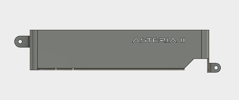
It was always intended to have an illuminated logo on the I/O shroud but I've never been too sure on how to achieve it. At first I tried cutting the letters out of the vinyl wrap to expose the acrylic underneath but I couldn't do a tidy job, and the letters themselves are too small for a vinyl cutter so that idea was binned off.
In what feels like a bit of a cheat given I made the I/O shroud prototype by hand, I'm now going to 3D print a new one so it's all straight and lovely (been having a few issues folding up a 2nd version), and was going to have the logo cut into it.
The thought was I can then cut out the bits of vinyl and tuck them into the letter spaces, but again we're talking about small letters and the 3D printer I have access to isn't likely to be accurate enough.
So, I'm now looking at the raft of illuminated I/O shrouds coming out on every RGB motherboard these days to draw inspiration on how I can best approach it. The latest thought is to have an engraved strip of acrylic inset into the printed I/O shroud. The strip is easy to cut with a laser, the printer is accurate enough to make the hole, and I can paint the strip with black acrylic paint and then etch off the letters. But I'm not sure if it'll look any good, and the more I stare at the sleek and unfussy work I have already, I'm now not even convinced I actually should put a logo on.
So I've done a Photoshop mockup to try it out. What do you think?
You've seen the board as it stands now:

Mocked-up inset panel
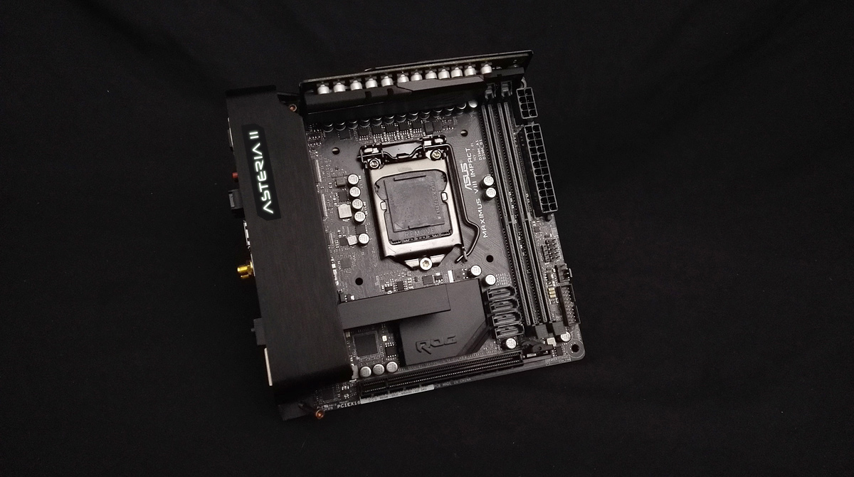
The more I look at it, the more I don't think I should. I'm not even sure I'm keeping the brush black aluminium wrap now and moving to the same matte black as the heatsinks and sound card - in certain light the I/O shroud, heatsinks and CPU block are all different black textures and it flies in the face of my original complaint about the board! Plus the RAM has lighting on it and the motherboard is underlit, so would a logo on the shroud - however discreet - be too "blingy" and take away from the clean and understated thing I got going on?
I'd value your input since I'm about 75% sure after posting this I'm not going to bother.
Cheers!
It was always intended to have an illuminated logo on the I/O shroud but I've never been too sure on how to achieve it. At first I tried cutting the letters out of the vinyl wrap to expose the acrylic underneath but I couldn't do a tidy job, and the letters themselves are too small for a vinyl cutter so that idea was binned off.
In what feels like a bit of a cheat given I made the I/O shroud prototype by hand, I'm now going to 3D print a new one so it's all straight and lovely (been having a few issues folding up a 2nd version), and was going to have the logo cut into it.
The thought was I can then cut out the bits of vinyl and tuck them into the letter spaces, but again we're talking about small letters and the 3D printer I have access to isn't likely to be accurate enough.
So, I'm now looking at the raft of illuminated I/O shrouds coming out on every RGB motherboard these days to draw inspiration on how I can best approach it. The latest thought is to have an engraved strip of acrylic inset into the printed I/O shroud. The strip is easy to cut with a laser, the printer is accurate enough to make the hole, and I can paint the strip with black acrylic paint and then etch off the letters. But I'm not sure if it'll look any good, and the more I stare at the sleek and unfussy work I have already, I'm now not even convinced I actually should put a logo on.
So I've done a Photoshop mockup to try it out. What do you think?
You've seen the board as it stands now:
Mocked-up inset panel
The more I look at it, the more I don't think I should. I'm not even sure I'm keeping the brush black aluminium wrap now and moving to the same matte black as the heatsinks and sound card - in certain light the I/O shroud, heatsinks and CPU block are all different black textures and it flies in the face of my original complaint about the board! Plus the RAM has lighting on it and the motherboard is underlit, so would a logo on the shroud - however discreet - be too "blingy" and take away from the clean and understated thing I got going on?
I'd value your input since I'm about 75% sure after posting this I'm not going to bother.
Cheers!
Last edited:
I think I'm with you on the brushed wrap. It looks good but it's not quite in keeping with the rest. As for whether you should have the lit logo or not....well I'm going to take the cowards path and tell you that's for you to decide. Mainly because I suspect that it could be one of those things that you have to do and get right even if you then decide not to use it. If it's not, it's certainly easier to not do it.
If you're going to do it, you could back-light it with some EL tape as I'm guessing the light source needs to be quite low-profile. If you can get a decent looking shroud with the letters cut out of it neatly, have you looked into filling it rather than trying to cut something that fits (good luck with that!) in the voids? By "fill", I mean something you can pour into the holes that then sets. A bit like those window decorations you did as a kid where you poured the plastic beads into the sections and baked it so they melted and set like stained glass (that wasn't just me, was it?!) - although you'd probably need something that pours and sets cold as I suspect baking the shroud would just melt it if it's 3D printed. Some sort of clear setting epoxy?
If you're going to do it, you could back-light it with some EL tape as I'm guessing the light source needs to be quite low-profile. If you can get a decent looking shroud with the letters cut out of it neatly, have you looked into filling it rather than trying to cut something that fits (good luck with that!) in the voids? By "fill", I mean something you can pour into the holes that then sets. A bit like those window decorations you did as a kid where you poured the plastic beads into the sections and baked it so they melted and set like stained glass (that wasn't just me, was it?!) - although you'd probably need something that pours and sets cold as I suspect baking the shroud would just melt it if it's 3D printed. Some sort of clear setting epoxy?
Filling the letters with something was the original idea if I "cut out" the logo during the print. Trouble is I'd still need to trim the vinyl wrap and maybe tuck it in a little to get clean edges, but I can't get the heat gun onto the vinyl without affecting the shroud (I can only do PLA, and that goes soft at 80 degrees like acrylic). If I could just fill in the letters then I'd have already given it a go. Hence the quandary now.
Lighting was going to be the same 5mm PCB strips I'm using for the other light panels. I have a bit of space above the control PCB and USB ports to squeeze in a bit of my opal acrylic, and then quite a bit of space to get the LED strip in where the I/O shroud does the vertical cover.
Cheers Cenedd, any other takers?
Actually, I've had a thought: I want to fill in the logos cut into the storage plates too. Now they're aluminium so heat isn't a worry, and conveniently not only did I use exactly the same drawing on the I/O shroud model as I did for the storage plates, but they're both 1.5mm thick too. So...
Step 1: experiment with filling in the storage plates (i.e. squirt a glue gun over the holes) to create plastic letters. If successful,
Step 2: print logo into the I/O shroud
Step 3: cut and tuck vinyl into I/O shroud letter spaces and insert formed letters into spaces.
Step 4: Profit!
Now to double-check the storage plates and the I/O shroud match
Hello to all, I thought I'd share a little something I've been working on. It's quite nice to be able to post this as I've been struggling with creative block on this small part, and it's delayed the last few cuts and holes needed.
I'm using the fan extension PCB that comes with my Maximus VIII Impact to split off fan control and temperature probes rather than the motherboard itself. This way I can keep a lot of the cable bulk tucked up out of sight by routing through the various tiny gaps and spaces between the case internals and the outer skin, including the PCB. And believe it or not, it's going in here:

There's a surprisingly large 20mm space between the PSU chamber and the outer skin once the case is fully assembled, which is more than enough for the PCB to sit in with the Molex power and all the various cables. Of course, as with pretty much every decision made on this project, what I came up with at the very beginning is never actually viable when you come to build.
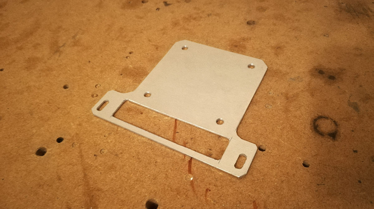
Yes, I can fit the PCB in there, but how do I actually get my fingers in to connect everything?!? So I've had the crazy idea of putting the PCB onto a runner so I can wire up the fans and whatnot and then slide it into place. After a few weeks of creative block dissipates, I start playing around in Fusion 360 and come up with this.

2-part design with a plate holding the PCB (yes, I did model holes for ALL the solder points on the back ) and a vertical stand which will be mounted to some brass standoffs.

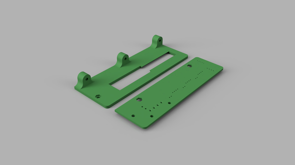
The runner is a simple 45 degree chamfered wedge about half the length of the PCB plate.
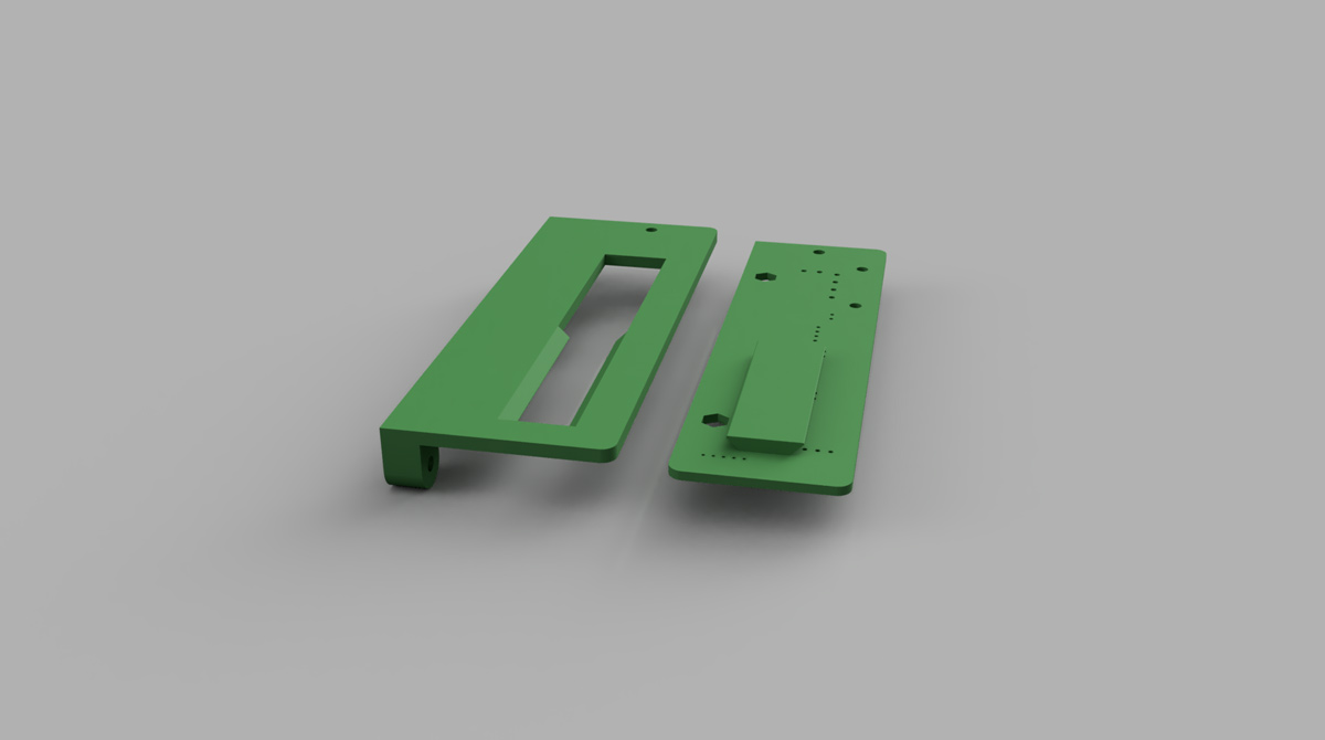
Line up with the full cutout, slide it into the chamfered bit and then pop in a short M3 screw at the opposite end to keep it securely in place. As this is intended to slide out of the rear side of the case, I'll need to chop out some material for an exit space.
I might make up a quick size prototype with some scrap acrylic, but this will only cost a couple of quid to 3D print at my local maker space so I'll more than likely just smash straight on.
Not much progress really, but it's still something to show you, hopefully my creative block has lifted and I can get my energy and motivation back to push on.
Catch you soon!
I'm using the fan extension PCB that comes with my Maximus VIII Impact to split off fan control and temperature probes rather than the motherboard itself. This way I can keep a lot of the cable bulk tucked up out of sight by routing through the various tiny gaps and spaces between the case internals and the outer skin, including the PCB. And believe it or not, it's going in here:
There's a surprisingly large 20mm space between the PSU chamber and the outer skin once the case is fully assembled, which is more than enough for the PCB to sit in with the Molex power and all the various cables. Of course, as with pretty much every decision made on this project, what I came up with at the very beginning is never actually viable when you come to build.
Yes, I can fit the PCB in there, but how do I actually get my fingers in to connect everything?!? So I've had the crazy idea of putting the PCB onto a runner so I can wire up the fans and whatnot and then slide it into place. After a few weeks of creative block dissipates, I start playing around in Fusion 360 and come up with this.
2-part design with a plate holding the PCB (yes, I did model holes for ALL the solder points on the back
) and a vertical stand which will be mounted to some brass standoffs.
The runner is a simple 45 degree chamfered wedge about half the length of the PCB plate.
Line up with the full cutout, slide it into the chamfered bit and then pop in a short M3 screw at the opposite end to keep it securely in place. As this is intended to slide out of the rear side of the case, I'll need to chop out some material for an exit space.
I might make up a quick size prototype with some scrap acrylic, but this will only cost a couple of quid to 3D print at my local maker space so I'll more than likely just smash straight on.
Not much progress really, but it's still something to show you, hopefully my creative block has lifted and I can get my energy and motivation back to push on.
Catch you soon!
Last edited:
Neat solution. 3D printing definitely seems to be getting into its stride now. Seen a few things in it now.
Why not model all the holes to avoid interference? It's not like each one has to be drilled out separately, that's the joy of additive construction, it simply doesn't print those bits. It's only when you start modelling all the fins in your rad that it can be considered obsessive! *nonchalant whistle*
Why not model all the holes to avoid interference? It's not like each one has to be drilled out separately, that's the joy of additive construction, it simply doesn't print those bits. It's only when you start modelling all the fins in your rad that it can be considered obsessive! *nonchalant whistle*
Cheers dude.
Should be pretty neat once printed. Most of the solder points are barely 0.5mm tall, so I was only going to model the big ones, but having explored Fusion 360 a bit more I found the proper dimensioning and repeating pattern tools, so it was a breeze to model every point instead. For some reason though it's taken me ages to get this done. I could visualise the entire case, the folds, the chambers, the spacing, but for some reason I just could not see how to make this runner plate work. But now I can make the final little chops and cuts into the case for this, and a few more pilot holes for other mounts.
Here's hoping I get some more progress done soon!
I'm not dead, just very poorly with insane work stresses triggering mental health woes.
I had a play with some self-clinching flush nuts I grabbed off fleabay for cheap and I must say things went extraordinarily well. Bit scruffy squeezing them into place with just a hefty C clamp but serviceable. When I can scrounge together some money amongst exorbitant heating bills and endless vet trips I shall be grabbing a 1 ton Arbor press to do these properly.
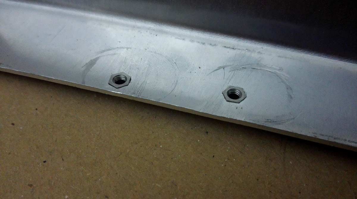
Bit of scrap alu, M3-01 type nuts for use in a maximum of 1.5mm thick sheet. Perfect. Drill hole size is supposed to be 4.4mm but I tested with a 4.2 and things seemed fine. Not fully flush because it's rough with a C clamp like I said, but hopefully the Arbor press will do a much better job. The specs for this type of flush nut say centerpoint of the hole should be a minimum of 6mm from the edge of the sheet to prevent warping. Where I intend to use them is in the middle of a strip 10mm wide, so that's going to be pushing it, but one of those tests was done about 5mm center from the edge and seems OK.
Quite excited at the potential of these things now for other projects")
Being able to mate aluminium panels directly together with the flush nuts is going to save me from many headaches, and I might even recut some of the lower body pieces without the need for shims and steel spacers just to hold a thread.
I'll try to check back in soon.
Cheers.
I had a play with some self-clinching flush nuts I grabbed off fleabay for cheap and I must say things went extraordinarily well. Bit scruffy squeezing them into place with just a hefty C clamp but serviceable. When I can scrounge together some money amongst exorbitant heating bills and endless vet trips I shall be grabbing a 1 ton Arbor press to do these properly.
Bit of scrap alu, M3-01 type nuts for use in a maximum of 1.5mm thick sheet. Perfect. Drill hole size is supposed to be 4.4mm but I tested with a 4.2 and things seemed fine. Not fully flush because it's rough with a C clamp like I said, but hopefully the Arbor press will do a much better job. The specs for this type of flush nut say centerpoint of the hole should be a minimum of 6mm from the edge of the sheet to prevent warping. Where I intend to use them is in the middle of a strip 10mm wide, so that's going to be pushing it, but one of those tests was done about 5mm center from the edge and seems OK.
Quite excited at the potential of these things now for other projects
Being able to mate aluminium panels directly together with the flush nuts is going to save me from many headaches, and I might even recut some of the lower body pieces without the need for shims and steel spacers just to hold a thread.
I'll try to check back in soon.
Cheers.
Last edited:
Well, that's good news - ill is FAR better than dead!
Those look a little like rivnuts.
Might need some sort of guide with the arbour press - something to keep the straight. A bit of rod with a hole drilled through it just big enough to clear the nut should work. Did something similar with some steel pins into alu plate this way - but with a bench vise doing the pressing because....I'm cheap
This is what they are, or at least a Chinese version thereof.
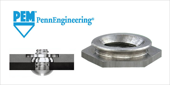
The insert is flush on both sides of the sheet, rather than having some form of stand-off clinched or riveted into the material. I'll be using these on the motherboard tray to mount the storage plate, and the insert being flush to both sides is key here since I have the motherboard lighting panel on the inside and 17mm of space on the other side to fit a 16mm tall storage assembly.
The insert is flush on both sides of the sheet, rather than having some form of stand-off clinched or riveted into the material. I'll be using these on the motherboard tray to mount the storage plate, and the insert being flush to both sides is key here since I have the motherboard lighting panel on the inside and 17mm of space on the other side to fit a 16mm tall storage assembly.
Thank you very much, @vvalter. Despite all the tiny issues with bends and measurements being slightly off, everything is panning out pretty much how I see it in my head, so I have a good feeling so far this will turn out pretty nice.
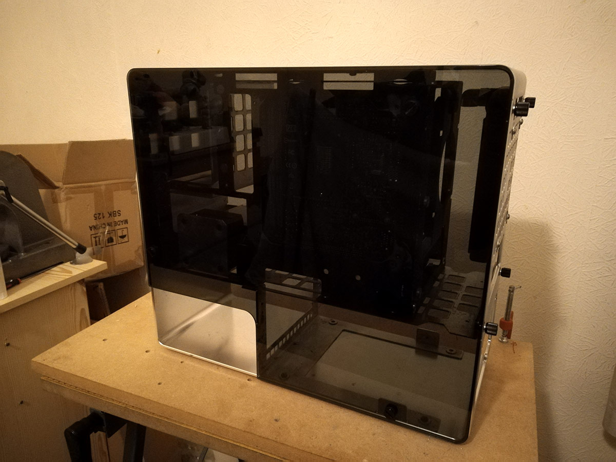
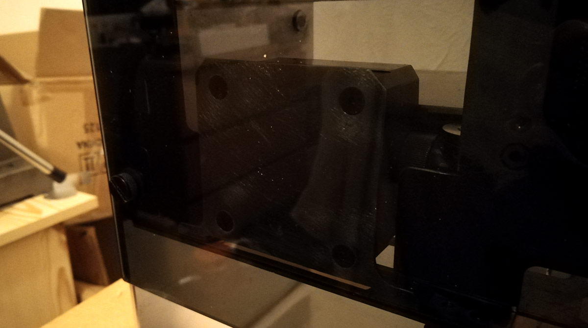
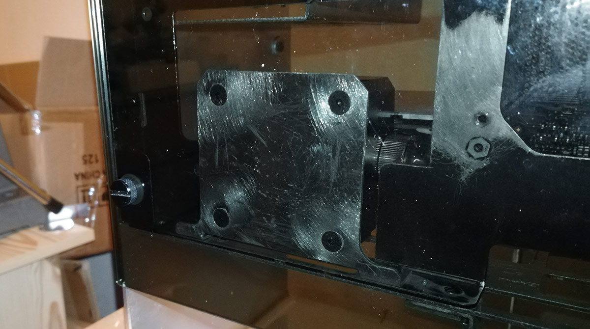
I'm desperately trying to make progress on this, even if it's just a little bit of measuring and prep work. I have mapped out a lot of final screw holes and placements, so hopefully I can get the drill out make the final modifications and powdercoat the internals. If I can get a completed case around my birthday (July) then I will be happy.
But it's all going to be crazy tight! This is just 1 view of the rear
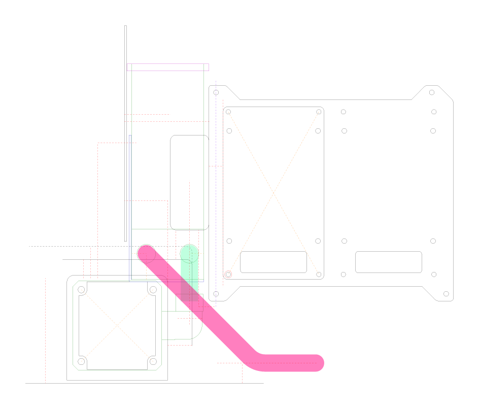
Last edited:
Greetings to all!
Blimey, it's been a while. 2018 wasn't the most fantastic year so many things were shelved, delayed and ignored but work does continue (albeit very slowly) and I thought I'd share some success with you.
Cast your mind back to the pump placement issues (or go have a read if you're new here - welcome ). I'm very happy to say a significant step has been made in resolving it: the DDC is finally in!
After all the toing and froing regarding measurements and poor accuracy, I confirmed that the distance from the edge of the GTX Titan and the glass side panel gave me an operating width of 43mm. DDC heatsink bodies are on average 20mm tall and my choice of pump top is a further 20mm. Factor in some manufacturing tolerance and the combined pump+top is 42mm tall. What that doesn't factor in though are the fins on the bottom of the DDC heatsink, which add 5mm, and DDC tops traditionally are fed from the top. All in and we're too big to fit. I've already discussed modding the Aquacomputer DDC top to have a side feed and using a custom stainless steel plate to seal off the top feed, so that keeps the top down to 20mm, but it was the heatsink that was the major issue.
The first plan was to just chop the fins off my Alphacool heatsink. Because Alphacool use a very thin thermal pad, removing the fins would reduce the heatsink to 19mm. Nice, but then put 1.5mm back on for my mounting bracket and we're up to the limit again. Plus, I didn't fancy the idea of getting nickel everywhere from cutting and filing, and I know I'd just want to strip it down and replate to keep things tidy. Same deal with the EK heatsink; easy enough to strip the anodising off the aluminium, but then it would need recolouring. But then I noticed Barrow take a slightly different approach.
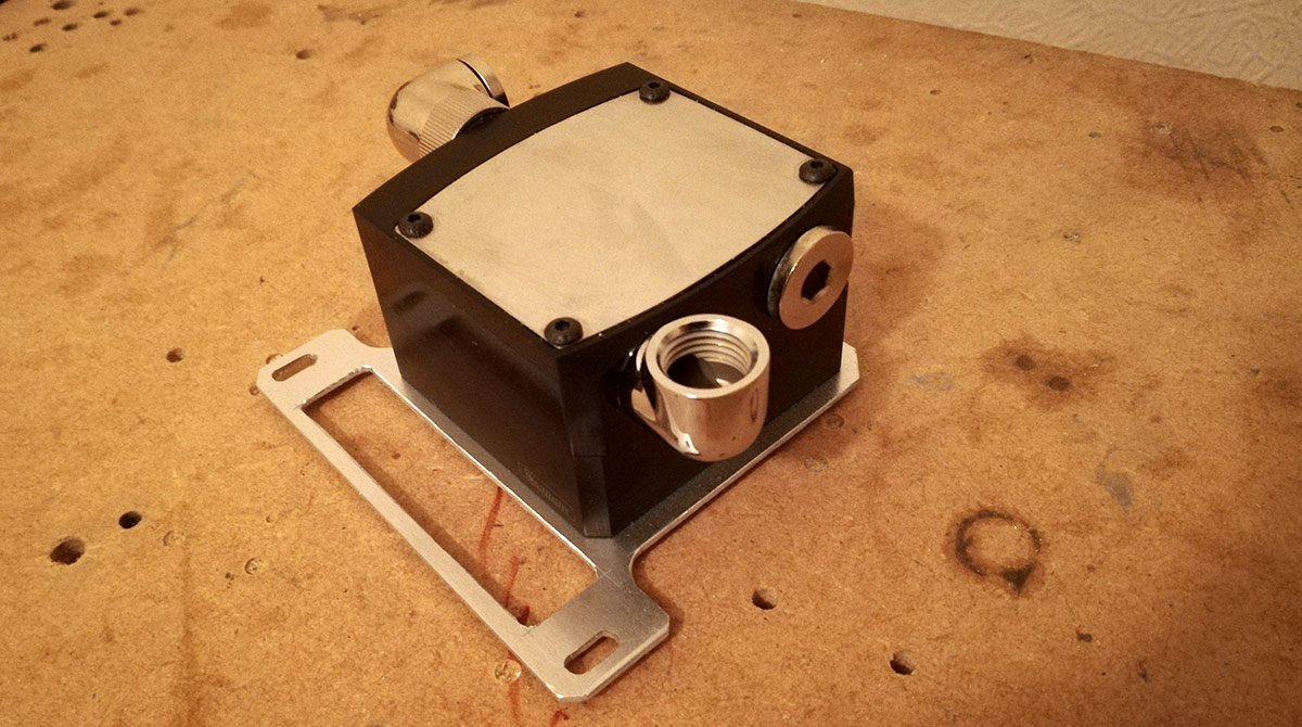
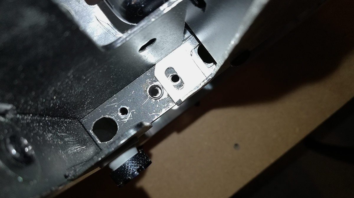
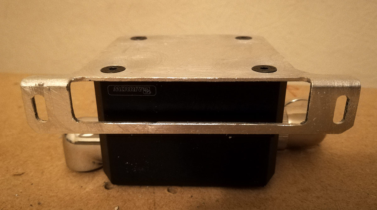
Barrow's heatsinks are actually in 2 parts: a chunky piece of aluminium which does the actual heatsinking and a thin body ring. Could I combine then the actual heatsink portion and mounting bracket? That would save a lot of space. So I grabbed one and redesigned my mount. Believe it or not I actually cut this by hand!
Scruffy? Yes. But I'm stoked to get the end result that good with just a step drill, coping saw and a crap wrist
Quick assembly to ensure my mounting holes are correct...
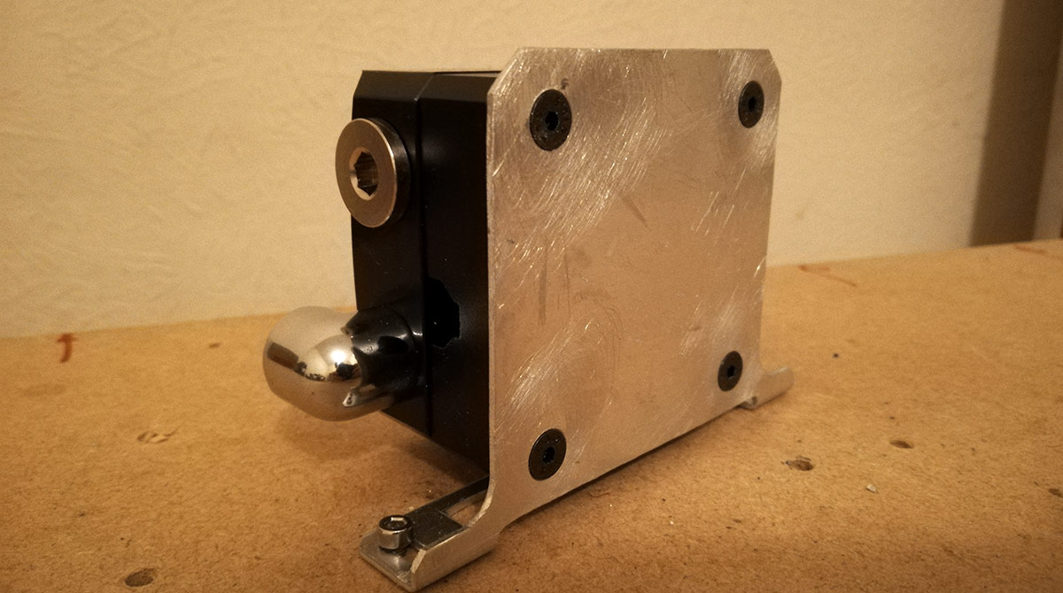
...and then fold that bottom tab into place.
Nice job, but does it actually work?
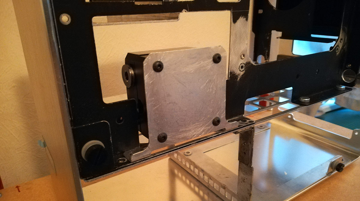
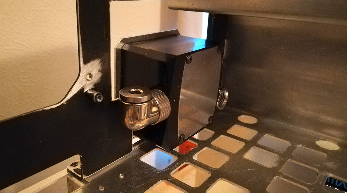
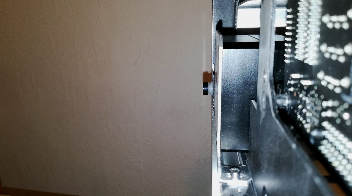
So far so good, but there's supposed to be a computer in there...
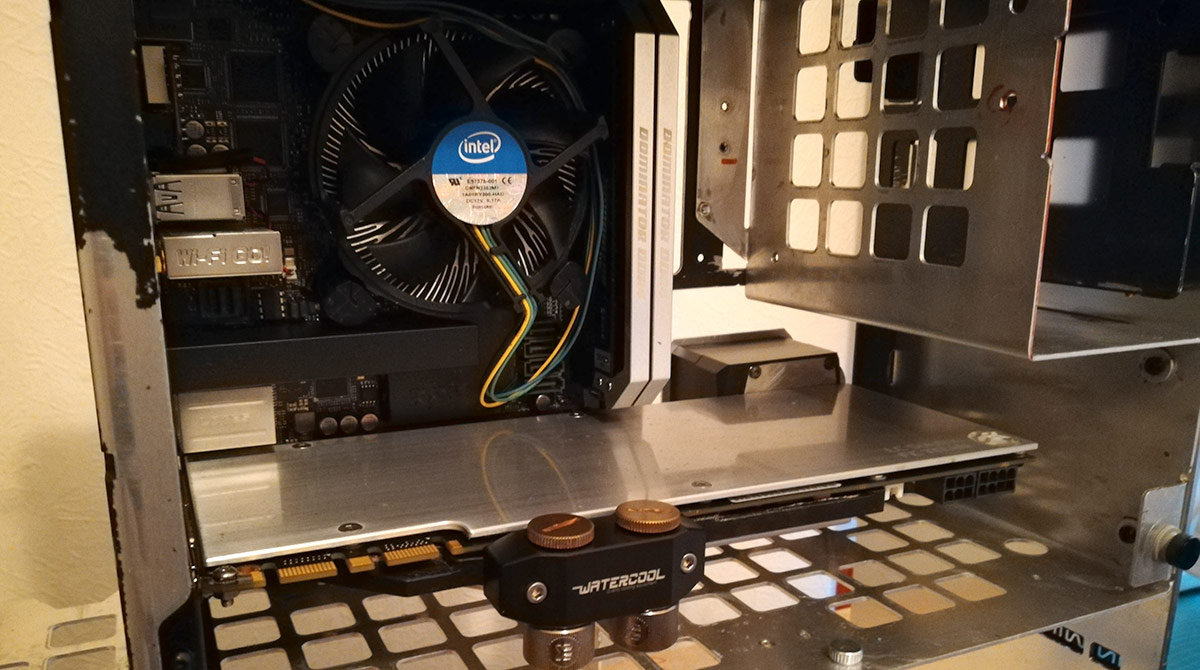
Hot damn that's tight, but it's not actually touching the Titan. Major win (and relief) #1
Now, in a perfect world the entire pump assembly would fit within that 43mm operating space so I can put the side panels back on with no further mods, but if need be I can put in a 1mm spacer to just edge the panels out without issue. Do I need to?
Maybe. The pump mount is almost flush with the case tabs that hold the side panel mounts. If the mount is flush then the glass will press on the pump and we'll get vibration and noise. But 1mm in this build is acres of space so I'm not too concerned right now.
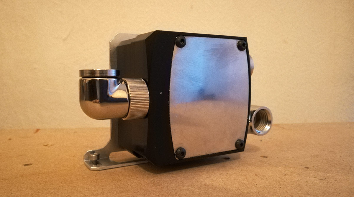
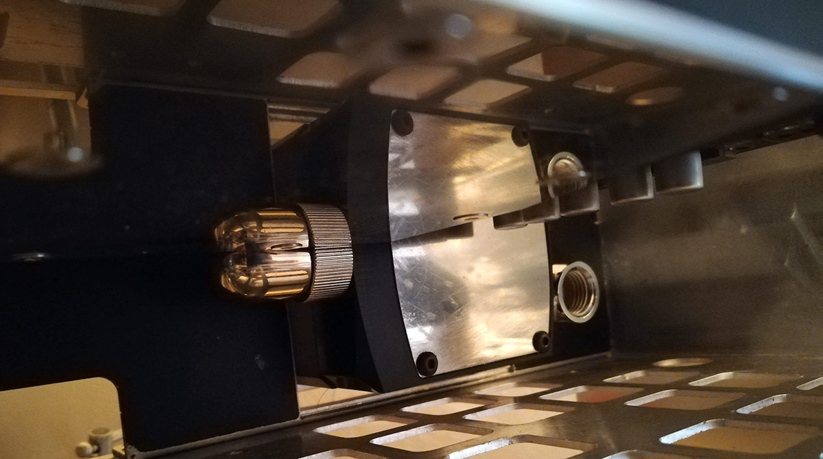
Now at this point I'm still just test fitting for viability. As a result I'm using standard dome head M4 screws to bolt everything together. The head height for those screws though is 2.3mm so of course they're not going to work. But the plan is to use countersink screws and get them flush with the mount.
Golden! Major win (and relief) #2
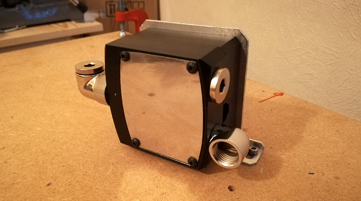
What I've not shown you here is a small failure. I'm using 1.5mm aluminium and the countersink M4 head is 2.3-2.5mm, so I wasn't sure if I could just slap a countersink into the mounting bracket given I'm missing almost 1mm of material to cut into. The idea at this point was to JB Weld spacers to the inside surface and give me more material to form the countersink. These spacers would also serve as proper alignment feet for the Barrow heatsink ring given it's just 8mm through holes and slides around the screws as you tighten up.
The Mod Gods were merciful and I found some perfect spacers: M4 tight through holes (4.1mm) and 8mm diameter. Perfection Nickel-plated brass though, but they won't be visible so didn't matter if paint didn't take, but a quick rasping on the mating surface got rid of the nickel there ready for the JB Weld. The JB Weld didn't take though as a 2mm ring just wasn't enough surface to adhere to and take the pressure of grinding down a countersink cone. Plus it was possibly the hardest form of brass in the universe. So the spacers popped off, but wonderfully the countersink in the aluminium took perfectly without deforming! Nice bit of luck there.
For now I've slid the spacers inside the barrow body ring so they can still serve as alignment holes, but for the build proper I'm going to drop in some 16mm long nylon spacers to fill the gap from the pump top's alignment feet and the mount, hopefully providing a bit of support so I don't warp the countersinks as the entire assembly is tightened.
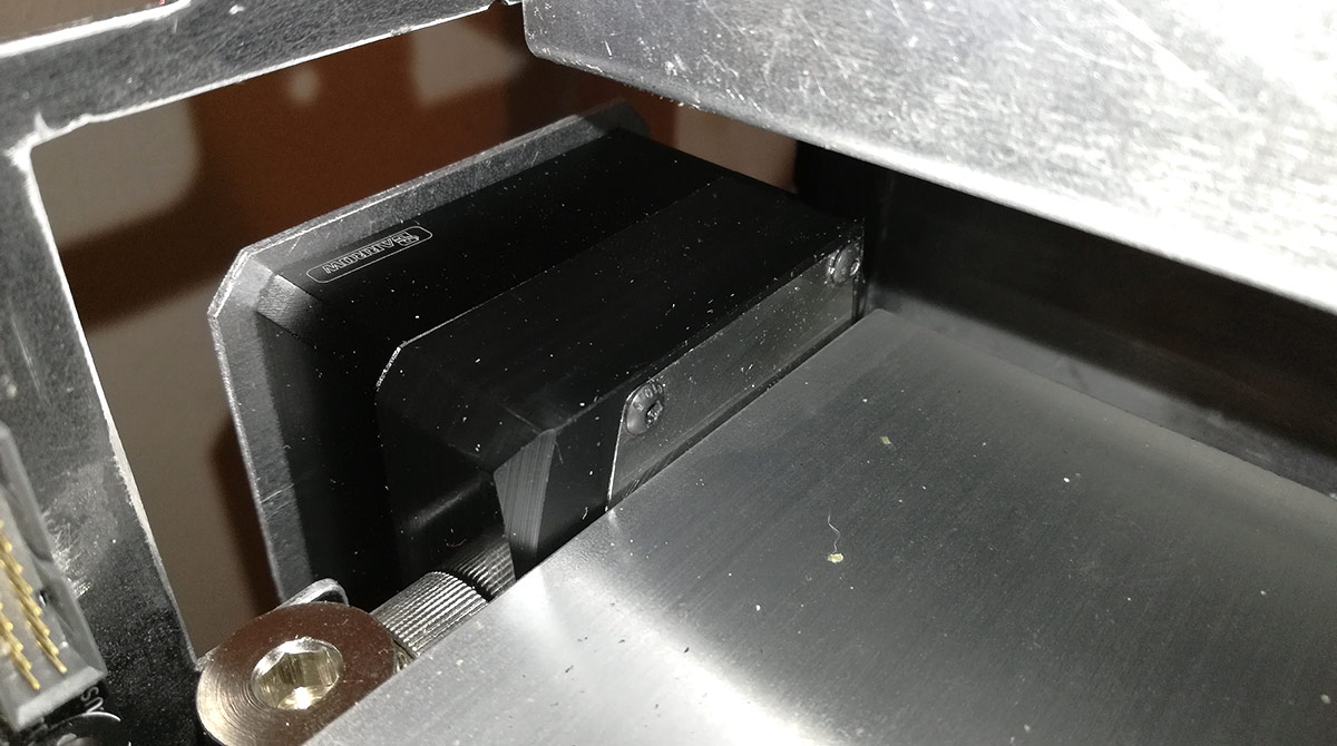
So moment of truth then. Does the glass panel actually fit back on?
Oh yeah Glass side panel perfectly screwed in. I can actually give the pump a push from the other side of the case and it doesn't knock against the glass. Major win #3
Speaking of the glass panels, I never actually told you about them either. Stay tuned...
Blimey, it's been a while. 2018 wasn't the most fantastic year so many things were shelved, delayed and ignored but work does continue (albeit very slowly) and I thought I'd share some success with you.
Cast your mind back to the pump placement issues (or go have a read if you're new here - welcome
). I'm very happy to say a significant step has been made in resolving it: the DDC is finally in!After all the toing and froing regarding measurements and poor accuracy, I confirmed that the distance from the edge of the GTX Titan and the glass side panel gave me an operating width of 43mm. DDC heatsink bodies are on average 20mm tall and my choice of pump top is a further 20mm. Factor in some manufacturing tolerance and the combined pump+top is 42mm tall. What that doesn't factor in though are the fins on the bottom of the DDC heatsink, which add 5mm, and DDC tops traditionally are fed from the top. All in and we're too big to fit. I've already discussed modding the Aquacomputer DDC top to have a side feed and using a custom stainless steel plate to seal off the top feed, so that keeps the top down to 20mm, but it was the heatsink that was the major issue.
The first plan was to just chop the fins off my Alphacool heatsink. Because Alphacool use a very thin thermal pad, removing the fins would reduce the heatsink to 19mm. Nice, but then put 1.5mm back on for my mounting bracket and we're up to the limit again. Plus, I didn't fancy the idea of getting nickel everywhere from cutting and filing, and I know I'd just want to strip it down and replate to keep things tidy. Same deal with the EK heatsink; easy enough to strip the anodising off the aluminium, but then it would need recolouring. But then I noticed Barrow take a slightly different approach.
Barrow's heatsinks are actually in 2 parts: a chunky piece of aluminium which does the actual heatsinking and a thin body ring. Could I combine then the actual heatsink portion and mounting bracket? That would save a lot of space. So I grabbed one and redesigned my mount. Believe it or not I actually cut this by hand!
Scruffy? Yes. But I'm stoked to get the end result that good with just a step drill, coping saw and a crap wrist
Quick assembly to ensure my mounting holes are correct...
...and then fold that bottom tab into place.
Nice job, but does it actually work?
So far so good, but there's supposed to be a computer in there...
Hot damn that's tight, but it's not actually touching the Titan. Major win (and relief) #1
Now, in a perfect world the entire pump assembly would fit within that 43mm operating space so I can put the side panels back on with no further mods, but if need be I can put in a 1mm spacer to just edge the panels out without issue. Do I need to?
Maybe. The pump mount is almost flush with the case tabs that hold the side panel mounts. If the mount is flush then the glass will press on the pump and we'll get vibration and noise. But 1mm in this build is acres of space so I'm not too concerned right now.
Now at this point I'm still just test fitting for viability. As a result I'm using standard dome head M4 screws to bolt everything together. The head height for those screws though is 2.3mm so of course they're not going to work. But the plan is to use countersink screws and get them flush with the mount.
Golden! Major win (and relief) #2
What I've not shown you here is a small failure. I'm using 1.5mm aluminium and the countersink M4 head is 2.3-2.5mm, so I wasn't sure if I could just slap a countersink into the mounting bracket given I'm missing almost 1mm of material to cut into. The idea at this point was to JB Weld spacers to the inside surface and give me more material to form the countersink. These spacers would also serve as proper alignment feet for the Barrow heatsink ring given it's just 8mm through holes and slides around the screws as you tighten up.
The Mod Gods were merciful and I found some perfect spacers: M4 tight through holes (4.1mm) and 8mm diameter. Perfection
Nickel-plated brass though, but they won't be visible so didn't matter if paint didn't take, but a quick rasping on the mating surface got rid of the nickel there ready for the JB Weld. The JB Weld didn't take though as a 2mm ring just wasn't enough surface to adhere to and take the pressure of grinding down a countersink cone. Plus it was possibly the hardest form of brass in the universe. So the spacers popped off, but wonderfully the countersink in the aluminium took perfectly without deforming! Nice bit of luck there.For now I've slid the spacers inside the barrow body ring so they can still serve as alignment holes, but for the build proper I'm going to drop in some 16mm long nylon spacers to fill the gap from the pump top's alignment feet and the mount, hopefully providing a bit of support so I don't warp the countersinks as the entire assembly is tightened.
So moment of truth then. Does the glass panel actually fit back on?
Oh yeah
Glass side panel perfectly screwed in. I can actually give the pump a push from the other side of the case and it doesn't knock against the glass. Major win #3Speaking of the glass panels, I never actually told you about them either. Stay tuned...
Last edited:
Very nice. So the aluminium plate is in place of a heatsink that would have been there had there been loads of spare space? If so, as long as you have a decent thermal interface, it should sink the pump's heat into the case. Dab of Kryonaut/Arctic Silver or something between the surfaces maybe?
And yeah, the latter half of 2018 wasn't that great. Hope it was nothing too disasterous.
And yeah, the latter half of 2018 wasn't that great. Hope it was nothing too disasterous.
Pretty much yeah. Rather than bolting a plate to the heatsink to mount it, the mount and the thermal contact surface is now the same thing. I'll be using the chunky thermal pad that came with the Barrow heatsink so we should be good for thermal transfer, especially as I'll be masking off the inner bit when I paint so the thermal pad will be on bare aluminium.So the aluminium plate is in place of a heatsink that would have been there had there been loads of spare space?
As for 2018, it was pretty rough. You remember those rescue rats I took in? Lost them all throughout the year. That's a lot of surgeries, euthanasia and cremations. The last girl Bindi went on New Year's Eve, bringing to an end not only the 2 year run with the rescues but also the 5 year run of having girls in the house.
Where the aluminium plate bolts to the main chasis, a bare patch (or just paint it while attached) and some thermal paste ought to get the the whole chassis as additional thermal mass.
Sounds like a rough year. My mum used to work at a vets so I've had cats for most of the last forty years....and you get attached to them. Hell, if Time Team ever do a survey of my mum's garden there's going to be questions asked!
Sounds like a rough year. My mum used to work at a vets so I've had cats for most of the last forty years....and you get attached to them. Hell, if Time Team ever do a survey of my mum's garden there's going to be questions asked!