(In Win 901) Asteria II: Rearmoured

Where the aluminium plate bolts to the main chasis, a bare patch (or just paint it while attached) and some thermal paste ought to get the the whole chassis as additional thermal mass.

That may be the route now. Originally I was going to have an active cooling system. Where the pump mounts is a slot about 50mmx8mm that passes through into the bottom chamber which is designed to mount a small laptop fan running gently on 3.3V and blowing up directly onto the heatsink body. Of course now the heatsink body is just a thin aluminium ring that only makes cursory contact with the big plate at the back, so it probably won't work now. I'll still put the fan in though, if anything because I've already chopped holes for it in the body work :p
 
OK, about those glass side panels.

The drive to retain as much of a stock look for the case as possible extends to keeping the same thumbscrews for the glass panels, so given I was replacing parts of the case which have panel mounts on them I needed to rebuild those mounts to fit the screws. Now although they're standard 6-32 threads, it took me a while to find brass standoffs that were 6-32 on both sides; usually they're 6-32 male and M3 female. Also they needed to be about 5mm in diameter too in order to fit the rubber grommets and mate with the glass.

Turns out I shouldn't have bothered :p

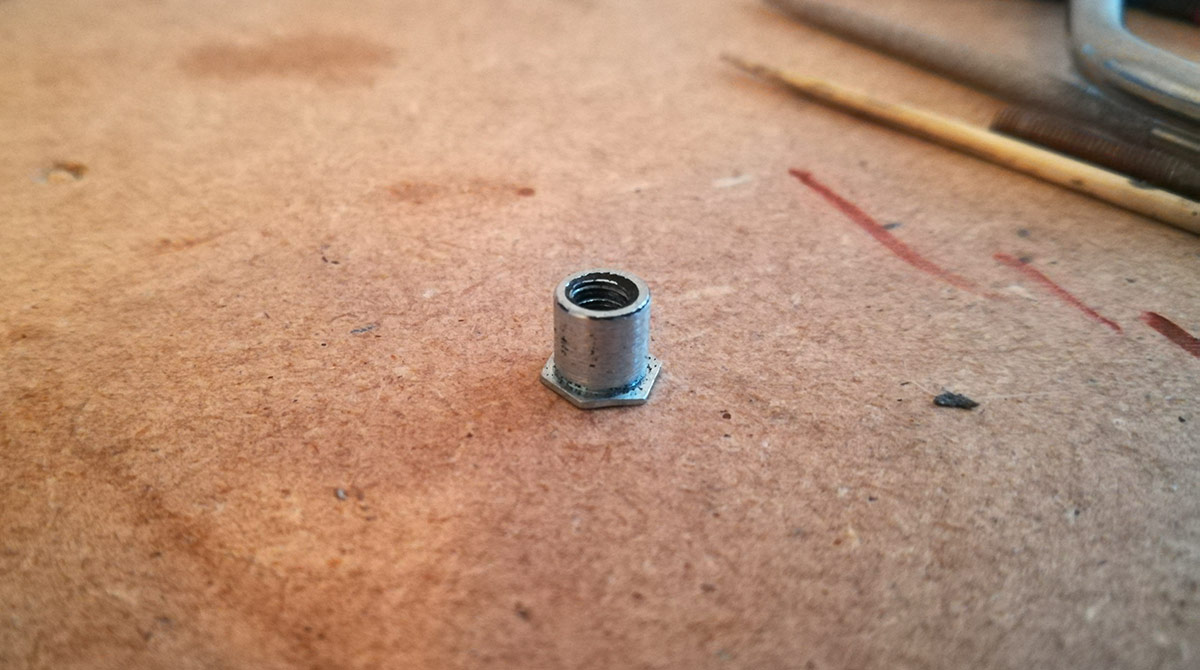
Eventually found some, marked up the new holes, tapped them into place and then realised they were too long. Not a problem, I'll just cut them down to fit, but then I realised a major error in judgement. Firstly, by chopping down the standoffs, there was very little female thread left to screw into, so there was no way the tempered glass could be supported safely even if the thumbscrews could actually go in. Then I realised that In Win had used through hole self-clinching threaded standoffs. This is how their thumbscrews would fully seat into the case and support the tempered glass.

So after carefully inspecting some of the original case parts, I tracked down the exact PEM fastener required, but the company in question no longer dealt with private customers, and I couldn't find any Chinese knockoffs (unlike my flush nuts). So I resolved this by doing something I didn't want to do: irreversibly cut up the original case :(

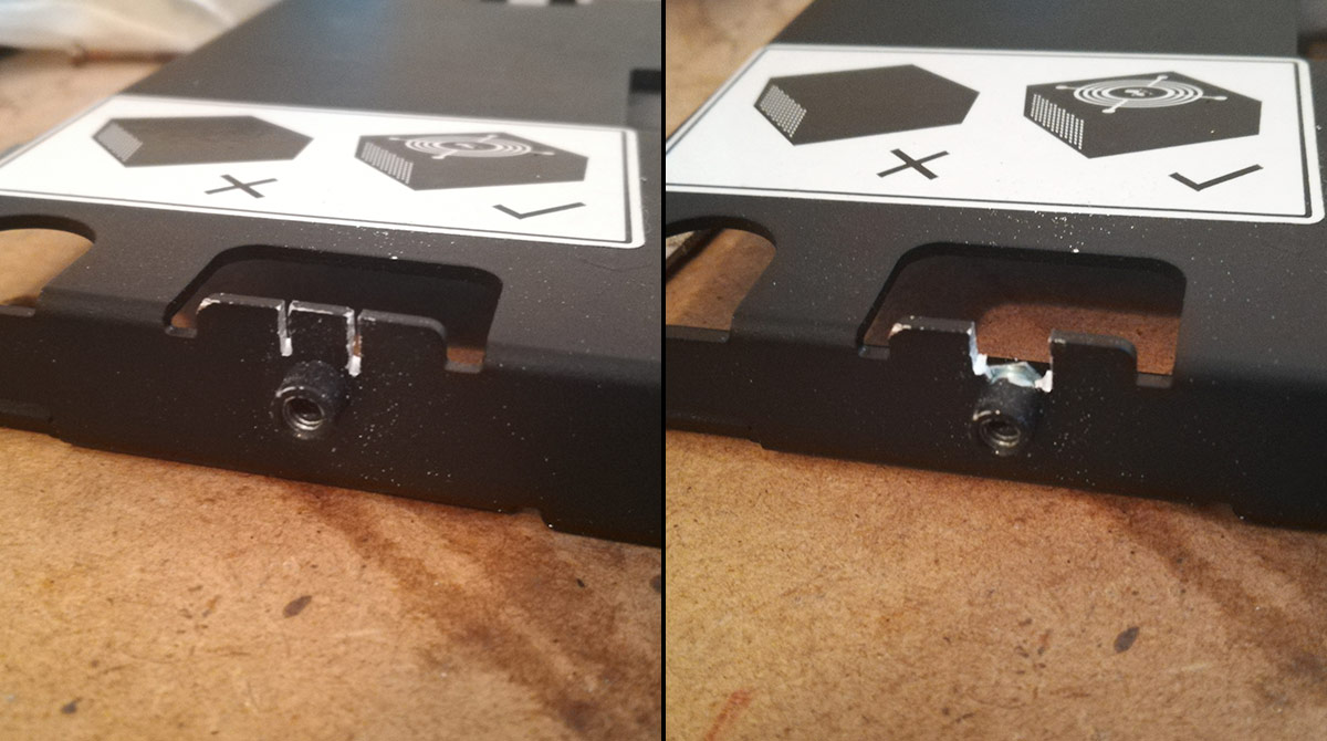
These particular standoffs fit into place by cold-forming sheet material into a little channel between its main body and a flange. As a result there's no welding or such required to get them in. So, by cutting into the aluminium either side of the standoff's main body, the material around it is actually no longer attached to anything. Gently pry it off and the standoff is released.

window_1-cut.jpg

window_2-insert.jpg


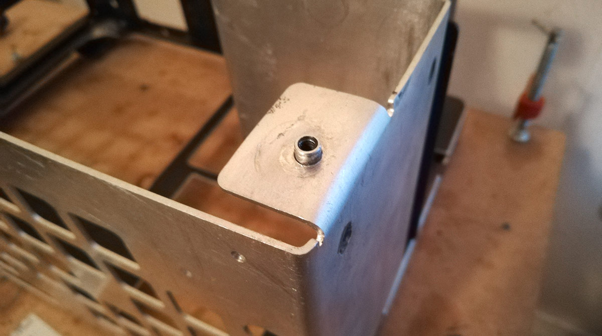
Since these things are steel pressed into aluminium, there's no deformation at all and can be re-used. So give them a quick sand down to remove the paint and get a proper through hole cut into my tabs (5.6mm in this instance). Then apply pressure.

window_3-lower.jpg

window_4-side.jpg


And in they pop!

My half ton arbor press was sufficient for the pressure, but I had to use a chunky M8 spacer I had floating around as a makeshift anvil. Worked nicely though. Unfortunately I couldn't get the arbor press into position for the main body where we have this big B-shape series of folds. So I used my body weight instead; laying the fully folded, tapped and drilled final body work down onto a piece of MDF with a hole in it, putting a dome head screw into the backside of the standoff placing a couple sheets of material onto the screw head and then generating half a ton of pressure by balancing on one foot and doing squats is really, really not how I want to insert these things. There was this big pop and I did not know if the standoff had gone in or if I'd trashed the whole damn thing.

It was the former.

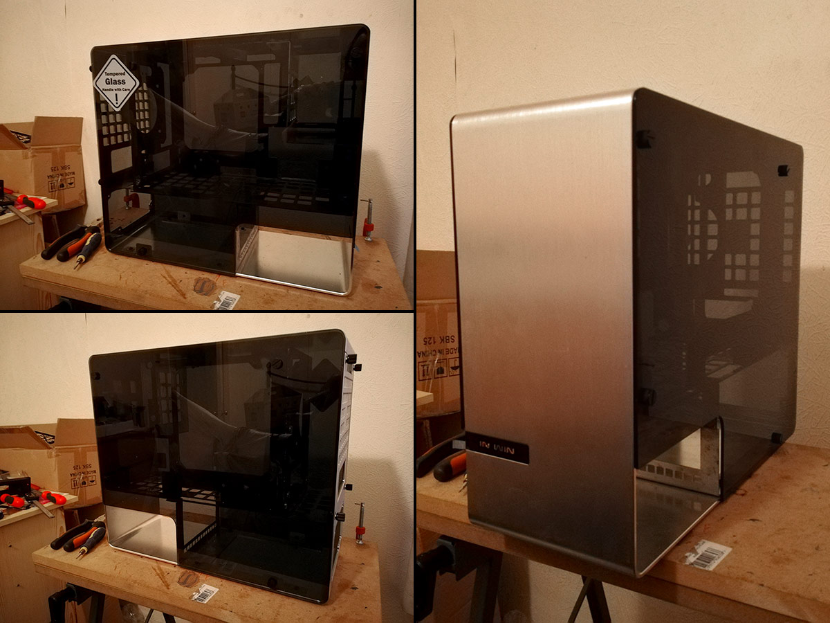
window_5-glass.jpg


Beautifully stock.
 
Last edited:
Thanks as always for those reading. There might be a second part to the pump story as I am still insistent on making a custom top, but truth be told now that I've seen the pump assembly in place I don't think I really need to. I may try anyway because I'm experimenting with laminating layers of laser cut cast acrylic into a final top. I may not use it for this project, but if it works it'll be invaluable for a project in the future (which is already heavily in the planning and design stage).

PSU mounts to cut next. Should just be a 2 second job cutting some aluminium angle with a scroll saw, but I want to do something a little more intricate with it.

3D printing, version 5 acrylic light panels and possibly custom power distribution PCBs to come.

Hopefully I won't leave it another year ;)
 
Sounds like an interference or press-fit. If you need to do any more that you can't get an arbour press to, you could drill the hole a little larger and add a drop of Loctite 368. Never coming out or spinning.

Should have posted before you hacked the original if you didn't want to do so. Some of us have acquired lathes in the Eagles style short break you had and might have been able to turn you a few. Looking good though.
 
Many thanks, @fantasticCG . She will be worth the wait. I'm trying desperately hard to keep some form of momentum going so fingers-crossed it won't be too long before something else is ready to show.

I'm jumping onto KiCAD to see if I can do some custom PCBs. Nothing special, just a glorified SATA power splitter to avoid a rat's nest of cables behind my storage plate, but it should be pretty slick if I can pull it off. Version 5 lighting rings hopefully cutting soon too.

Better go find my soldering iron :p
 
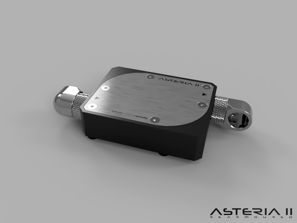
Hey there. Might as well post some pretty renders of part 2 of the "seriously, haven't you fixed or discarded the DDC yet" saga.

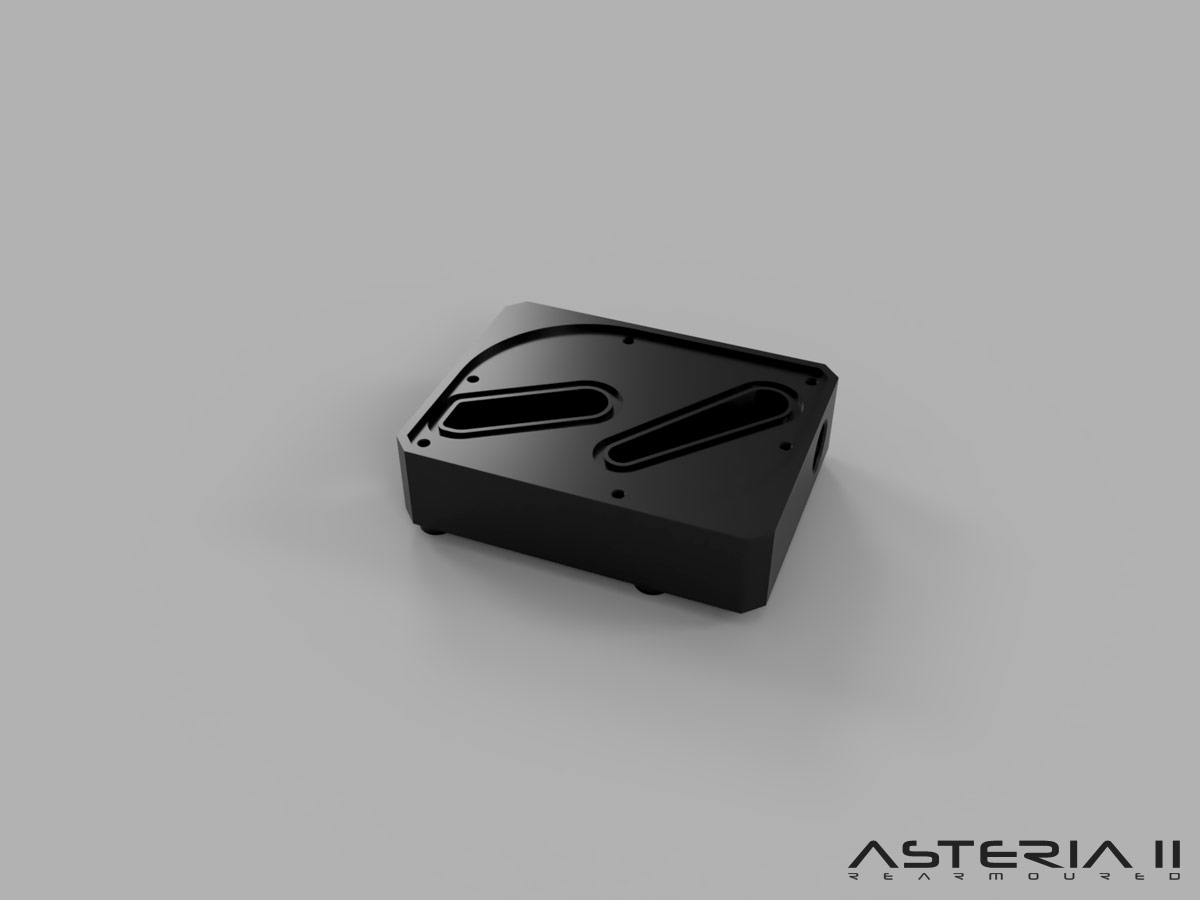
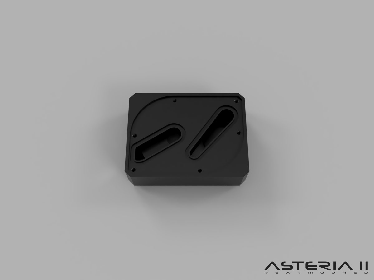
With the pump assembly perfectly in place, it now transpires that I can't make the tube routing from pump to radiator through the floor to work without a stupid, ugly amount of adapters, and it's too tight for soft tube too and just kinks. So as suspected it's time to return to the custom pump top idea. Completely redesigned this time though. Enjoy the renders :)

new_extended-model.jpg

new_extended-oring1.jpg

new_extended-oring2.jpg

new_extended-oring3.jpg


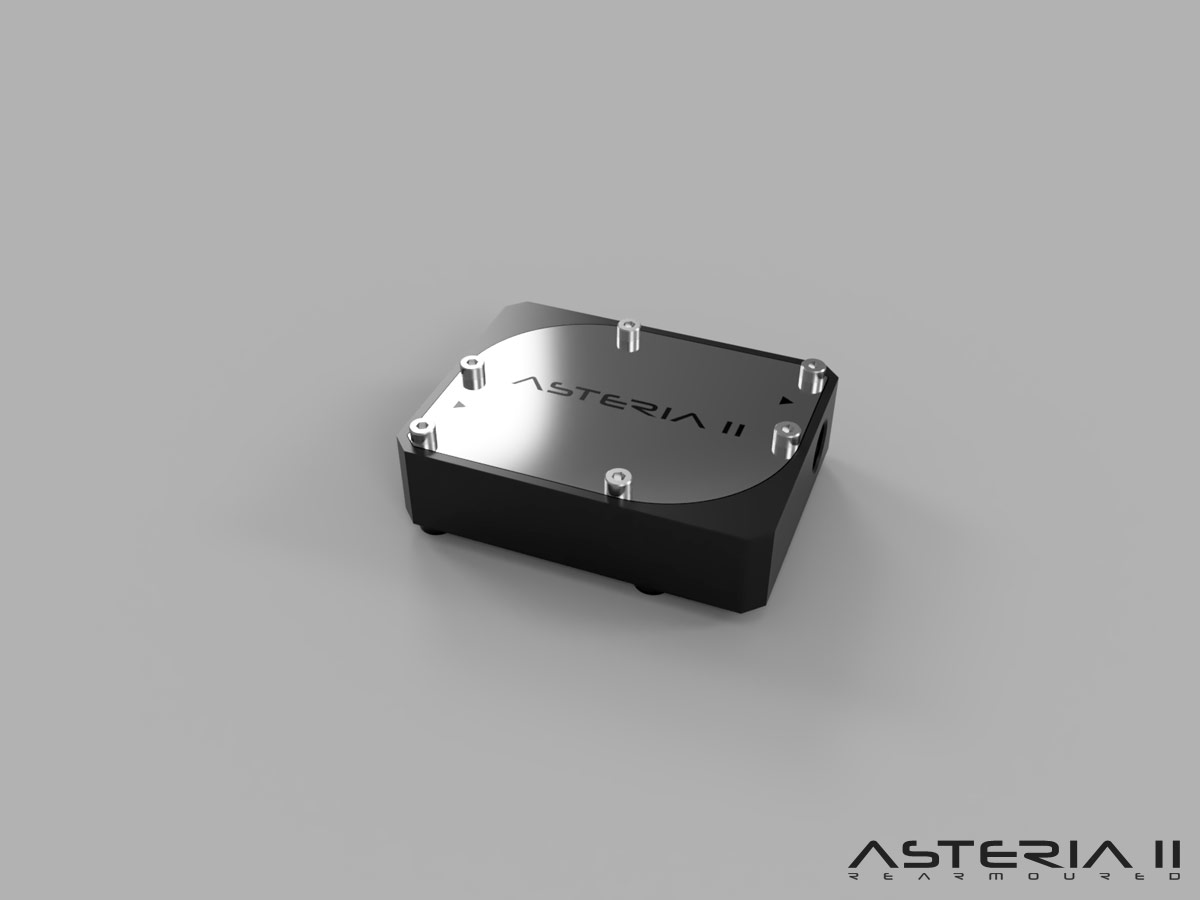
I've extended the body width by 19mm to cover the distance between the pump body and the radiator holes in the case floor, so now an EK 90 degree rotary fitting will align directly above the radiator port's centre line, with sufficient vertical space to get a compression fitting on and angle some tube. That extension means I've gone down a distro plate approach to go from the volute outlet to the port, which has of course necessitated o-rings and a sealing plate.

And yes, the strong resemblance to Aquacomputer's DDC top is intentional; wanting to keep the look, I've drawn on many design cues from their dual DDC top to create mine as a homage to the top I've had to discard. I don't think I can get in trouble for that :p

To allow for measuring and manufacturing tolerances I will be using Mayhem's ultra clear soft tube for this part of the loop, but it's very clear for soft tube, 13mm OD is indistinguishable from 12mm OD acrylic when piped in, and once I have Oil Black Pastel coolant running you'd be hard pressed to tell the difference between the soft and hard tubes I think.

And I'm also very excited to say I'm discussing manufacturing of this right now. CAD models are being verified as I type :D
 
Last edited:
Update! Minor change of plan already :p

As I was fine-tuning the CAD work, I realised that I'd completely forgotten a fundamental point in this entire build: clearance spaces. And specifically, the entire reason I've been working and fighting with side ports is because I have zero space on the top face. So why in the hell did I put cap head screws along the horizontal centre line? They're going to foul the bloody graphics card! What a wally!

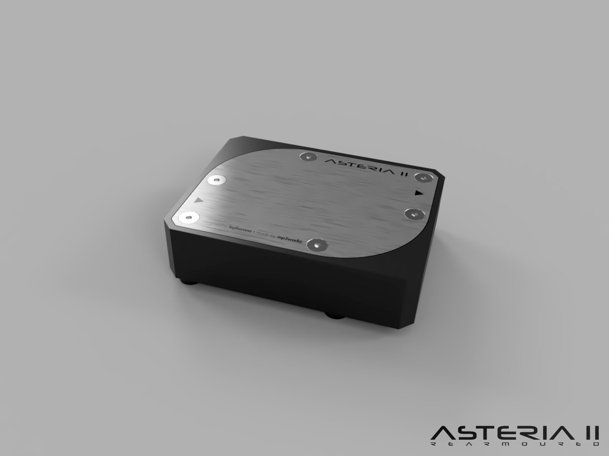
So as I was reworking things, it also occurred to me that as I'd gotten a bit carried away with replicating Aquacomputer's aesthetic, it would actually look out of place with my aesthetic. Countersunk screws solve both of these issues! So, the portion of the pump top that is visible peeking over the graphics card will have countersunk screws just like the GPU backplate. Also, my logo would be totally obscured by the GPU too.

So new model and new renders :p

extended_model_rev3.jpg

extended_model_rev3-fittings.jpg


But this IS getting made :D
 
Last edited:
Who’s making it?

The clue is in the latest render ;) Lucas from Mp5Works, a modder down in London.

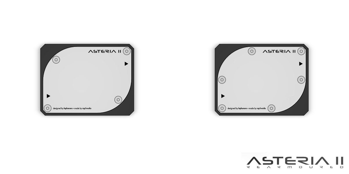
There's also been another tweak in that I've gone down to 4 screws instead of 6 for the top plate. I like the visual symmetry of the 6 screws, but it feels a bit cluttered. But then 4 screws is more spacious but doesn't have quite as nice a flow. I feel I've messed Lucas around too much already to be procrastinating over 4 or 6 screws since the ball should start rolling this week :p

Either way, that top plate is 1.2mm stainless steel at only 77x57mm in size, it's not going to flex with 4 screws. I might try and get a comparison render up later on to see what people think.

Ah I see, do you mind sharing cost or via trust? Curious to see vs some quotes I’ve had.

Tell him to just screen shot the model if you’re worried about wasting his time but it’s easy to move holes and update.
 
OK, because it's a slow day at work and I'm procrastinating, the 4 or 6 screw thing is bugging me. So I've done 2 quick layouts to illustrate (Fusion 360 in a browser is awesome!).

extended_screws-compare.jpg

extended_4-screws.jpg

extended_6-screws.jpg


Looking at these without any lighting or textures and fancy projections, I think I'm actually satisfied with the 4-screw variation, it feels a lot more "open". The 6-screw symmetry is very nice but does feel a little cramped when I apply the graphics to the plate.

Your thoughts?
 
Last edited:
OK, because it's a slow day at work and I'm procrastinating, the 4 or 6 screw thing is bugging me. So I've done 2 quick layouts to illustrate (Fusion 360 in a browser is awesome!).

extended_screws-compare.jpg

extended_4-screws.jpg

extended_6-screws.jpg


Looking at these without any lighting or textures and fancy projections, I think I'm actually satisfied with the 4-screw variation, it feels a lot more "open". The 6-screw symmetry is very nice but does feel a little cramped when I apply the graphics to the plate.

Your thoughts?
They're both lush! I especially like how the corners and the screws both basically say parallelogram. On that basis I'd say 4 screws does it fine. 6 screws takes it towards looking like a hard drive a little bit.
 
Cheers dude, it does looks pretty special. I hope the real thing comes out just as well!

My guy has done a CAM test on acrylic and it looks stunning, so much so I almost changed my mind on material. I'll see if I can get some pics.
 
My first time glancing through but some very nice work in here lePhuronn. Those designs look especially cool. Also one of my most liked cases looks wise!

I’m on and off the idea of doing my own case but haven’t decided/committed just yet.

Anyhow keep up the good work! I’ll be looking forward to future updates! :)
 
Thanks tyler, keep your peepers peeled!

This new pump top should be milled the weekend, I'm doing some paper tests of revision 5 (yes, 5 :mad:) of the motherboard lighting ring, and if I can clear out the spare room/workshop/bombsite I can get my scroll saw set up to make the PSU mounting brackets (because cutting aluminium angle properly with a hack saw is apparently too much for me).

Frustratingly a long way to go despite being so close to finishing the metal construction.
 
Back
Top Bottom