(In Win 901) Asteria II: Rearmoured

I'm not dead, just very poorly, and even more annoyed at the mistakes I've been making as of late.

I doubt anybody will be interested in steel spacers to replaced stripped threads in aluminium :p but hopefully I'll have something fun to report on soon.
 
Glad to hear you're not dead! Hope you're feeling better soon.
Cheers for lighting up the thread again and bringing it to my attention that I'd entirely missed updates since about April! Looking good so far. Nice to see it take shape in the flesh. Pump top looks good. Was going to comment that it looked circular rather than spiralical (yeah, I know that's not a word....and you probably know that I don't care so we're even) but yeah, with a forstner a circle is a better target! Hell, even with an endmill unless you've got CNC it'd be a tall order by hand.
I'm at least as interested in your steel spacers as you are in the spring-like swarf that came off my hybrid fly-cutter/carbide lathe tool plate-flattener thing* :D Have you effectively created low-profile steel nuts? That maybe sit in the aluminium's hole with a flange to stop it pulling through?

*last time I get surprised by hot-rolled steel turning up and making my life awkway/interesting!
 
Hi there Cenedd.

My steel spacers are nothing so fancy. Essentially I was so pre-occupied with getting an aluminium alloy I could bend manually I forgot to factor in that something so soft wouldn't hold threads for long. I went overkill and chopped up some 2mm mild steel strips and just drilled and tapped them, then JB Welded the suckers into place. It's a bodge, but it's all in places that will be covered by other plates and whatnot.

But guess what? I have to bodge my bodge because I messed up a little :D. To ensure that the spacers were correctly aligned with all the screw holes, I actually screwed everything together so the JB Weld could cure for a bit. Unfortunately, my intention of removing the screws after 4 hours or so didn't come to pass (I blame the rats and their infinite cuteness) and I found wonderfully rigid screws locked tight after the 24 hour cure was completed.

So I've now had to drill out the damn screws (pillar drill is a godsend) and rethread the holes. It will come as no surprise that 1 out of 4 holes didn't take a rethreading, so I've stripped a thread out of the very material that was supposed to fix the previous stripped thread issue!

I'm talented, me :p

Everything does screw together nicely now though, even though there's not an accurate fold in the entire thing. Looks boss from a distance ;)
 
Oh, and I got a spring-loaded tap follower in the end as per your recommendation. But none of my small tap wrenches have a point or a divot for the tap follower to hook into, and I never had time to 3D print a little guide hat. Ended up just smashing the tap into the drill press chuck and disengaging the drive belt. Worked nicely, actually.
 
Cheers Andy, hopefully my mental state will return to form soon. I have LED strips to solder and some lovely opal acrylic shapes just staring at me yearning to be fitted (and corrected because I didn't factor in solder points on the back of the motherboard).
 
Oh, and I got a spring-loaded tap follower in the end as per your recommendation. But none of my small tap wrenches have a point or a divot for the tap follower to hook into.

If it's the one I'm thinking of, the end is reversible to be either a point (for taps with a divot) or a hollow (for taps with a point). Unless you've got the lesser-spotted taps of awkwardness, one should work. Have to say I've done a few by power-tapping it with the mill on slowest (50 rpm) and some by chucking the tap and turning the chuck by hand. It's harder (or at least I get more paranoid) as the material gets softer because you get less feel for what's happening. So some I've started chucked for alignment and then continued it by hand. Andy's were hand-tapped with the follower because it was into acrylic and I didn't want to have to start from scratch!
 
My steel spacers ....
I'm talented, me :p
I'm a 'more talented idiot's than most of the idiot-proof things I've come across so I share your pain. Similar to why some of the screws in a project I did recently (where aesthetics didn't matter) are M4 and some are M5. Thought about retapping the M4's as M5 but knew I'd then just end up with a mix of M5 and M6 :D
 
If it's the one I'm thinking of, the end is reversible to be either a point (for taps with a divot) or a hollow (for taps with a point). Unless you've got the lesser-spotted taps of awkwardness, one should work.

Mine is reversible, however the ratchets for anything smaller than M8 taps are smooth-topped, like so
s-l300.jpg


The bigger taps (like my G1/4) go into a wrench leaving their dimply ends exposed for the follower to take a grab of.

Thought about retapping the M4's as M5 but knew I'd then just end up with a mix of M5 and M6 :D

I'm trying to stick with M3 on everything because it's stock, except for a few load-bearing bits where it's 6/32. I almost retapped the failed retap M4 but then I'd have 1 single, solitary M4 that you couldn't see but I'd know it was there. And it's going to bug me forever knowing how many bodges are on this thing, even if you don't see them.
 
Ah, that makes sense. You want one of these then: http://www.arceurotrade.co.uk/Catalogue/Cutting-Tools/Tap-Wrenches/Bar-Type-Tap-Wrenches
If you're using hand-taps, you need to be reversing them to break the chips periodically anyway so the ratchet is almost more of a hindrance.
Could probably have done the failed M3 as 6/32....but you'd still have known it was wrong. In my case, I was making a cross-brace for some bed-raisers (gammy knees) I'd made for my mother (couldn't have a bed that would take simple off-the-shelf efforts, oh no, far too easy!) so my primary concern was not having to spend time in A&E because it had collapsed!
 
Yeah, I noticed the ratchet action was pointless when I messed up a test light panel. I have one of those bar wrenches for the bigger taps but it doesn't close enough to hold the smaller ones. So far just disengaging the pillar drill's drive belt has worked nicely with just a finger's worth of pressure on the plunge mechanism so the tap can bite and feed.

Good shout on the 6/32 rethread actually, my dome head screws don't look any different to the M3. Right now the JB Weld innards are holding a new thread quite well, but I can see that giving up the ghost further down the line.
 
Dag nab it - that's my quota of good ideas used up for the rest of the year! ;)

It didn't go to waste, nice new solid thread in place.

Working on a pitch for a new job at the minute so plans of getting scruffy aluminium sanded and cleaned up have been put on hold. Just when I get some energy and motivation to carry on other people get in my way!

But next up is taking a jigsaw to some 20mm thick acetal offcuts...the pump top experiment is imminent :D
 
Well, nothing's going too well right now, but I've not posted anything in ages so I thought I'd throw some stuff online and maybe just tell a tale. So, we have some OK stuff and some "for crying out loud" stuff. And some rough photos to go with it.
 
Blanking Plates
What is some good news is that I've finally finished the core construction of the case. Still lots of new holes and whatnot to put in for tube runs, mounting points, etc, but it's nice that the procrastination is done with and I can stop faffing about.

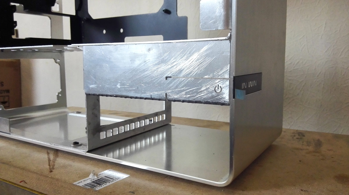
To keep the stock look going I wanted to blank off the front half of the radiator area underneath the glass panels, but I also need easy access to that area for working with tubing, running cables and the DDC cooling fan. So the idea is to have 2 plates attached with thumb screws that are folded around the upright and horizontal parts of the case body. Unfortunately previous bending attempts on tiny flaps of alu met with the same issues I had on the larger case parts; try to bend too wide a piece and the bend radius shoots up.

Let's try perforating the fold lines then and see if we can lessen the resistance.

Fold lines marked and center punched
blanking_punched.jpg


Drilled (forgot to switch to a 1mm bit before starting :p)
blanking_drilled.jpg


Lined up in the folder
blanking_folder.jpg


And folded up, with no real improvement in bend radius down the length.
blanking_folded-1.jpg

blanking_folded-2.jpg

blanking_folded-3.jpg


I guess ultimately I'm not reducing the amount of material to be folded with such small holes. Ah well, no big. Looks fine once the holes are filled and put in place.
blanking_rear-placement.jpg


Annoyingly though it looks like something got into my bag of smaller metal bits and scratched them during a recent tidy up. Should buff out no problem before powder coating, but it's an extra job.


I have a choice of panel for the front side:
blanking_power-choice.jpg


Both replicate the stock 901's power button in that it's a springy tongue of material resting against a tactile switch. I'm going initially for the version with a power icon cut into it so I can try and light it up.

For this to work as intended, I need to slice off a bit of the new bodywork to give an inset for the plate to press into.
blanking_mount-shape-1.jpg

blanking_mount-shape-2.jpg


It's about 3mm deep and angled up to the "hinge" on the blanking plate.

So when the plate is in position...quick balancing act!
blanking_mount-position.jpg


The upper half of the plate is flush against the bodywork, and the folded tab on the far side is pushed over 90 degrees to give a tight grip. The lower half then can be pressed in and trigger a tactile switch set up behind it.

In place
blanking_power-placed.jpg

blanking_power-placed-2.jpg


Minor disappointment in that with all the bending issues I've had all dimensions are just a tiny bit off what was originally planned, so the power button strip is now about 3mm lower than it should be and no longer lines up with the In Win logo on the front of the case. I really hope I can buff those scratches out without resorting to filler :( they're not actually deep so fingers-crossed smoothing them off and then powder coating will hide it.

I might have spares though, assuming they're not scratched up too. Worst-case scenario I just remake them, but I'm inclined to just use alu angle so I don't have to worry about folding it. The thumbscrew tab bends nicely, and I can just round off the sharp angle edge. An option...

Either which way, with this bit done and the lower portions finally supported, threaded (again) and all screwed together, the actual reconstruction is done. Finally. Hurrah.
 
Last edited:
Motherboard light panel
What is decidedly "meh" is the light panel intended as a halo around the motherboard. I drew a few bits up and went laser cutting some acrylic.
light-panel_base.jpg


5mm thick Opal 050 acrylic. This is actually my second attempt after the original clear acrylic version shifted slightly in the laser cutter and went wonky. Plus I couldn't find anybody who'd sandblast small pieces of thin acrylic (original plan) and there's no way I could get the finish I wanted through manually sanding :p

Annoyingly though, it didn't feel right once I'd cut it. Hell, it didn't even cut correctly. Using exactly the same settings as the clear acrylic, there were some areas when doing the opal wouldn't go fully through and had to score and snap some bits out (with razor blade sharp edges my scarred thumbs can attest to). I passed it off as a quirk of the material given it only has 37% light transmission.

But then I got home and did some test fits and things still weren't right. It's too thick.
light-panel_measure-1.jpg


I forgot that opal is cast, not extruded, so we have manufacturing tolerances to come into play. Something like +/- 10% thickness + 0.4mm. OK, so 5.74mm is within tolerance. It's 1mm thicker than my initial clear panel though.

light-panel_measure-2.jpg

A bit better

light-panel_measure-3.jpg

Um, hang on, that's ridiculously out of spec. Is that why the sheet I bought cost so little? It's actually "B" grade?

I need to thin this down a bit. Let's quickly line up some way of pinning this down. Wrap some electrical tape around some M4 screws to fill the holes better.
light-panel_screws.jpg


And drill a hole pattern into my work board. Unnecessary pictures ahoy!
light-panel_screw-pattern-1.jpg

light-panel_screw-pattern-2.jpg


Let's get rasping!
light-panel_screwed-panel.jpg


And after about 5 minutes I stopped because even 6mm thick panel should've still fit, but could be falling foul of solder points on the board that I didn't need to consider before.

Quick and dirty mapping solution. Masking tape the top side of the panel:
light-panel_masking-tape.jpg


Apply blue felt-tip pen to the bigger solder points, ICs and chokes on the underside of the motherboard and then press down onto the light panel in position:
light-panel_mobo-position.jpg


Worked well enough to get an idea of where the bit items were, but not well enough to be picked up on camera, so no pics of the transfer I'm afraid.

Drilled out some shallow holes and a rough n ready router channel:
light-panel_drilled-1.jpg

light-panel_drilled-2.jpg


Now the board can sit in position and rest correctly without anything interfering.

Except that it doesn't. Something is still not right and I can't quite see where it is. And it turns out I didn't even need to make all those holes for solder points because they're not the reason the board isn't flush, so I've trashed the piece.

So 3rd time's a charm and I'm going to make another one, this time in 3mm acrylic so the cast manufacturing tolerances will keep it within my original plans.
 
Last edited:
Waste not want not
Since the actual shape isn't changing I thought I'd get the LEDs sorted anyway and give it a test.
light-panel_soldering-fun.jpg


Cool white 3528 LED strips on a 5mm thick PCB wrapped around an inner frame so the light shines outwards
light-panel_led-mount-1.jpg

light-panel_led-mount-2.jpg


Just as an experiment, I covered the underside of the light panel with silver foil to see if it'll help with internal reflection.
light-panel_foil.jpg


And then the LED ring is slotted inside the light panel
light-panel_assemble-1.jpg

light-panel_assemble-2.jpg


Note that all wires will be sleeved at a later date :p


So, let's give it a test!
light-panel_solo-test-1.jpg

light-panel_solo-test-2.jpg


Yay, ish kinda. The bottom dead spot isn't too much of an issue because the GPU covers that entire side of the motherboard so you won't even see it (shame), but the internal size of the light ring didn't divide to 50mm evenly enough to fill the gap. The corners are frustrating though. I know there are holes in the way so it was never going to be perfect, but I thought the LEDs had a much wider viewing angle than this to help fill the dead spots.

But then also look how the light doesn't fully penetrate the opal acrylic. Opal 050 has 37% light transmission and is perfect for lightboxes, but I guess that only applies if you're lighting underneath not directly into the sides.

So, time to look at other acrylics for my 3rd attempt...
  • Opal 030 has 70% light transmission so that should help, but it's more frosted than a solid white
  • Polar White Frost looks similar with a 60% transmission
  • Crystal Clear Frost (oxymoron there, Perspex?) has 90% transmission, which is likely to be blinding given how damn bright these LEDs are

There are also a matching pair of panels like these for the storage covers which I haven't built the LED rings for, but could suffer the same issues. We'll see when I get to them, but if I'm changing the acrylic for the motherboard then I do want the storage to match when the lights are off as well as on.
 
Last edited:
It's not so bad when the motherboard is put into position.
light-panel_mobo-test-1.jpg

light-panel_mobo-test-2.jpg


But you can definitely see where the light isn't filling into spaces left by narrow angle LEDs. I think that can be rectified with more light transmission. I'll probably tweak the internal dimensions too for a tighter 50mm division to lessen dead spots.


Why not throw some red gels and my phone's torch into the mix for a laugh :D
light-panel_mobo-test-3.jpg

light-panel_mobo-test-4.jpg

light-panel_mobo-test-5.jpg


Of course bear in mind that the Dominator Platinums have the cool white lighting to them too, so we'll have an extra soft glow from the RAM, and the Titan backplate is so very shiny as well which should catch any stray light and reflect it up into the CPU area. Could work rather nicely.


That's me done for now, hopefully I'll be making some more progress soon. Cheers for looking!
 
Last edited:
Cheers dude. Should be a little better when I've made some tweaks. When viewed from the top, there should only be a thin sliver of light around the edges of the board just for an accent with a soft flood into the case. It's a little bit of a shame that the Titan will obscure the bottom edge though.

The storage panels are getting the same treatment, but there's nowhere to hide with them, they have to be fully lit and as even as possible, but I have a little trick up my sleeve which hopefully will help. Panels coming soon!
 
Back
Top Bottom