(In Win 901) Asteria II: Rearmoured

Oh, and @Cenedd the PA-09 is glorious :D

They're a bit fiddly to have to do both wings separately but at least you can see when you've shoved the wire in far enough but not too far. You sometimes find the pin sticks in the crimper after it's been crimped but you can sort of wiggle it out. Main thing is the crimps come out well. There are two variations (something like a PA-20 and 22 iirc) that have larger sized anvils. I made up some gash 2.54mm pins for testing something yesterday and had a little trouble getting the larger set of wings into the shell. It might have been better with a fractionally larger anvil than the largest one on the PA-09 but the crimp was secure, neat and easily tweaked with a combination of the flat ends of the jaws and a gentle squeeze in a crimp slot but turned 90 degrees.

Incidentally, their solder sucker is really good too....if you happen to make a pigs ear of anything. There's a flexible tube on the end that can tolerate the heat of the iron so you can get it right over the joint while it's still molten. Still not easy to remove two 2x10 pin headers when you've soldered them into the wrong side of the PCB though :-/

As for your PSU wiring, are you keeping the same number of wires but just routing them via the 10 pin area so there's one near run in the middle?
Different length wires will have a slight increase in resistance but for the length we're talking here and the purpose, I can't see it being an issue. Similarly there can be a difference in time taken for the signal to get down a longer wire. That could make a difference if you were talking about something like Cat6 at silly speeds but I wouldn't have thought there was anything here that's going to even notice let alone care.
Benski's right though if you're looking to reduce the number of wires a particular current is traveling down.
I'd be tempted to try to make it as one-to-one as possible and look into the reasons that any aren't one-to-one. I think I've read that loops at the far end (mobo end) can be used by the PSU to check voltage at point if delivery.
 
The wiring idea is to have the motherboard end only have single wires and move the double-wire nonsense further up towards the PSU where it can be hidden. I can t-splice the doubles easily enough, but that's a faff to do and sleeve, even though the PSU end will be hidden behind a vanity plate.

Corsair's stock SF600 cables are already sleeved so I can't see the wire itself to tell how thick it is. It could be a bunch of sense wires on the 5V and 3.3V lines, or it could be doubling up for ALL TEH AMPZ. I'd be surprised though if it were the latter, standard 18AWG cable is rated for 13A or something so why would you need the capability to push 2 lots of 26A through the 5V and 13A through the 3.3V? That seems a bit overkill.

Still, I'm not messing about, if Corsair want double wires going into their 5V and 3.3V lines then I'm not arguing :p I just didn't want to t-splice ;)
 
Depends where the double wires connect to. If it's just two pieces of wire connected to one pin at each end - ie doubled up - then you could achieve the same ampacity by using thicker wire. If they're connected to two different pins at the PSU end then either it requires two outputs from the PSU to supply enough power - which seems unlikely - or one of them is a sense wire that's reading the voltage at the ATX connector so it knows it hasn't drooped. In that case, you may find that it doesn't correctly read the voltage at the end of the wire and compensate for droop. Found a little on it here: https://www.overclockers.com/forums/showthread.php/754386-Sense-wires-how-important-to-PSU-operation
 
well. I found this completely by accident and told the wife i would be down in 10mins.....

That was an hour ago and i have just read through the entire build. The level of detail here is phenomenal, and i cannot wait to see it finished! will be following for sure!
 
You flatter me, sir. And extend my apologies to the better half :p

I'm wrapping up some design tweaks for updated metalwork and currently working out what I'm going to do about the double wires on the PSU. Hopefully I'll have something tangible to post an update with soon...assuming I don't kill myself chopping the C13 connector off my kettle lead and using something else ;)
 
Last edited:
chopping the C13 connector off my kettle lead and using something else

Are you thinking spade crimps that fit the pins in the PSU's C14 or modifying the PSU to replace the C14 as well? Probably no reason you couldn't replace the C14 inlet on the PSU with a (3D printed) grommet and hardwire the cable straight into the PSU. Could then have a C14 a metre down the cable (just butcher a hot-cold lead) if you want it to be pluggable before the mains.
Clearly soldering or otherwise 'playing' with the mains side of a PSU if you don't really know what you're doing is a bad plan....but I have a feeling that LePhuron knows what he's about there.
 
but I have a feeling that LePhuron knows what he's about there.
You flatter me in thinking I have any clue what I'm doing! :p

I'm replacing the C13/C14 combo on my internal extension with an Amass MR30. Stumbled across then when looking at XT90 connectors for my Ender 3 Pro. Small little things that should solve my issue of having a detachable power cable in tight spaces.

The low profile right-angle extension I robbed out of a Node 202 is too short to run the entire length of the case and stick out the back for a C14 connector. Fortunately, it is long enough to clear the fiddly internal routing and end in the big ole space underneath the radiator. Originally I was going to have the extension terminate in a C14 about a metre or so away from the case (there is no space to put a panel mount C14 onto the case itself), but the MR30 is small enough I can get it in and out of the case when fully assembled.

The MR30 is rated for 15A and 500V so it's plenty, despite being a piddly little thing. Will print some chunky strain relief and mounting clips for it too. I do need the cable to be removable though so if the MR30 doesn't work out I'm going chok block and hiding it under the bottom radiator.

Shame it's a yellow connector though :(
 
The MR30 is rated for 15A and 500V
That's DC voltage. Given UK voltage is around 320V peak, I would definitely want to reassure myself that those connectors were appropriate for AC mains supply.

It's possible I had a quick look around at MR series connectors but there's no mention of AC rating at all. It's often a lower voltage than DC ratings though. It'd likely be fine once connected but it might be one of those "don't power it up while unplugged/hotplug it" things about a personal build.
 
I did think about the AC issue but my Google Fu is weak and couldn't find anything about the viability of using DC connectors on AC sources. Fortunately I won't have to worry about hotplugging because this is for the mains cable, if it ain't plugged in then it won't power up :P

I do have a 20A chock block in reserve. Shall I just go with this and not risk the MR30, do you think?
 
MR30 is a really neat solution. And if it's only accessible by you, and you wouldn't fiddle with it while the power cable is plugged in, I've seen worse.

It's just the worry of when someone else has to use the thing, but I guess this PC is unlikely to get moved on quick :D

I've got my broadband modem, router, and Powerline all attached to a socket running from a ceiling rose. Literally wired into the lighting ring. It's definitely not sensible and I'll definitely have to remove it when I move out! :P
 
Oh, about those double PSU wires...

I was having a read about the operation of sense wires and I get the impression that Corsair's Platinum units require them to be present (you can bin them off for the Gold rated units) otherwise the thing won't even kick in. And given the nature of sense wires, there's not much choice in where they go. So, double wire it is then. However, because my 24 pin is only a short one (30cm max, likely 25cm) and I have super slim wall wire stock, it's likely I can double crimp at the motherboard end but run both wires inside the same piece of sleeving to give the appearance of a single cable.

Best of both worlds if it works.
 
Best I can find is that connector uses 16 AWG wire i solder buckets. With the usual disclaimer of "I am not a qualified electrician" (and you should therefore probably consult one for a more accurate answer!") it seems to be rated at 10 Amps for stranded cable. If that's the case, it would equate to over 2kW of juice so you ought to have plenty of safety margin there.
Best reference for stranded wire ampacity I could find was this: https://www.jst.fr/doc/jst/pdf/current_rating.pdf
Simply because it specifically states (at top of table) that its for stranded wire. If you're using solid core, i think it'd be higher so still good.
 
Actually stranded wire carries more current due to having more surface area (if were talking AC):

https://en.m.wikipedia.org/wiki/Skin_effect


However, because my 24 pin is only a short one (30cm max, likely 25cm) and I have super slim wall wire stock, it's likely I can double crimp at the motherboard end but run both wires inside the same piece of sleeving to give the appearance of a single cable.

This is genius if it works!
 
This is genius if it works!
Oh, it'll work in concept ;)
double-wire_sleeve.jpg


The trouble is you don't get a circular cross section in the wire. It may not be visible when all bundled up with the other wires, but it's something I'll need to work on.

It's made me realise though how much the modding community, especially the pros, seem to completely misunderstand paracord. I've seen so many people complain they hate paracord because it "looks like shoe laces" when it just doesn't if you do it properly. And by doing it properly I mean don't use 550 paracord which is what everybody says is the size you need.

Rubbish. This is why:
550-paracord_wires.jpg


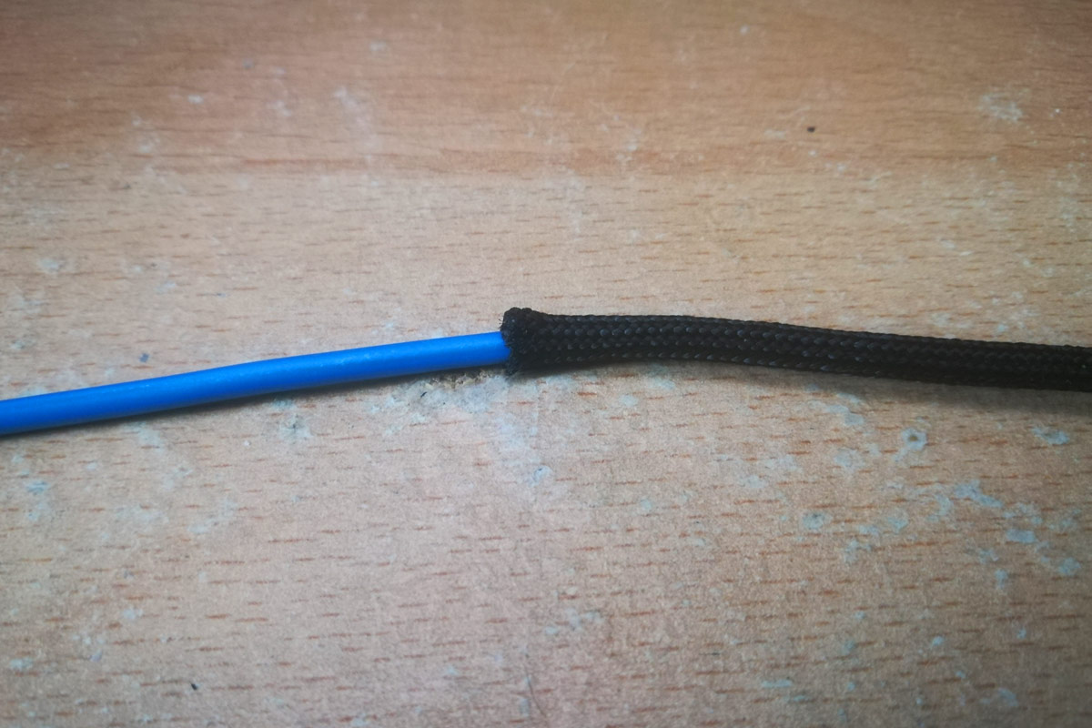
That's 550 paracord with the strands taken out. The top wire is stock 18AWG chopped off a dead PSU, the bottom wire is my thin wall 17AWG. With the cores taken out, 550 paracord is over twice the width! There's no way you can stretch paracord enough to compensate for that amount of slack, and if you can't get it tight to the wire then of course it's going to be all saggy like shoelaces. Hell, it's even a bit too slack to house both the 17AWG and 24AWG I used for the double wire test above.

Now, match the paracord with the wire and it's much better. Here is same 550 paracord sleeved over a chunky-ass 16AWG neutral wire taken out of a kettle lead
16awg_550-paracord.jpg


That's not stretched out so it will slim down, but even then 550 paracord has thick fibres, so it's never going to be super slim.

Go back to my front panel sleeving pictures and tell me that looks like shoelaces :p I paired thin wall 24AWG (1.13mm OD) with 325 (a loose 2mm OD cord) and 275 paracord (proper 2.4mm OD) and it's super tight. The thin wall 17AWG (2.0mm OD) wire will be paired with 425 paracord (3mm OD) and it's all snuggly snuggly and stretches super tight.

Shoelaces my ass...

/rant
(had to vent that one)
 
Last edited:
Actually stranded wire carries more current due to having more surface area (if were talking AC):

At mains frequencies, I don't think that kicks in until the conductor is over 8.5mm in diameter. At consumer level stuff, you'll get more cross-sectional area of conductor in the same diameter of wire with solid than with stranded - due to the gaps where it doesn't tessellate perfectly. I can't find anything specific from the IEE but the Wikipedia page on AWG states (hidden in the text just above the table) that you have to determine the equivalent cross-sectional area of the wire to determine its ampacity.

@LePhuronn Your shoelaces look lovely! ;-P
 
any update?
I'm afraid not, sorry. Between crazy lockdown workload and personal circumstances of late taking what little free time and money I have, there's nothing left in the tank to push on with this. I was set to get some painting done but there were some errors with the new laser cut metal pieces which I needed to fix first, then Winter kicked in :( and Covid means I can't get to my local maker space to cut the acrylic for my light rings.

But since you've made an account specifically to post here, I'm greatly encouraged to see there's still interest in this old project. I shall do my very best to get something done if I can get the damp out of the work room and tidy up after the roof leak.
 
Back
Top Bottom