

You are using an out of date browser. It may not display this or other websites correctly.
You should upgrade or use an alternative browser.
You should upgrade or use an alternative browser.
(In Win 901) Asteria II: Rearmoured
- Thread starter LePhuronn
- Start date
More options
Thread starter's postsYou're very welcome, and thanks for commentingNice log, thanks.
")
Well crikey, could it be there's an update to be had? There is indeed! Time for some soldering methinks...
So, rejigging the case layout to accommodate the 360 radiator means there's no space to use the stock front panel connectors. The original plan was to veroboard some switches and LEDs together, but about 18 months ago (I know, I know) I thought "let's just go all-in with this project and make up everything custom I can". So out with the veroboard, in with some custom PCB design
If you're looking at doing PCBs, I strongly recommend EasyEDA. The online editor is just incredible for creating your circuit schematics, hooking in real manufacturing parts and generating PCB layouts with proper footprints. EasyEDA is in the same group as LCSC for components and JLCPCB for PCB manufacturing, so you have a one-stop-shop to design, make and populate your custom bits.
4-pin fan headers and SATA power I sourced elsewhere, but the EasyEDA editor allows you to create your own component footprints too, so I grabbed the Molex specs and drew up the missing parts.
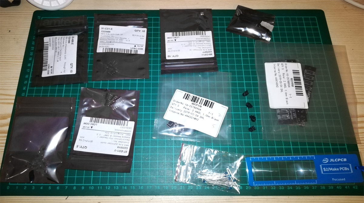
And here we are! (Excuse the potato phone pictures, the room is very gloomy. Tidied up as best I can)
No extra charge for black board, no extra charge for simmer board thickness, and 5 boards for very little money if you stay within a 100x100mm footprint. Winner.
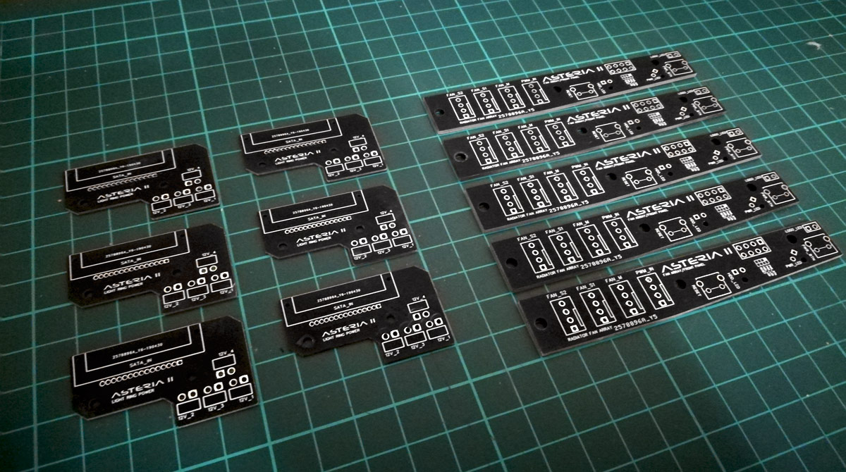
I know you're not going to see them once installed, but if Asus can put a ROG logo on their Thor PSU heatsinks then I can sure as hell brand my PCBs
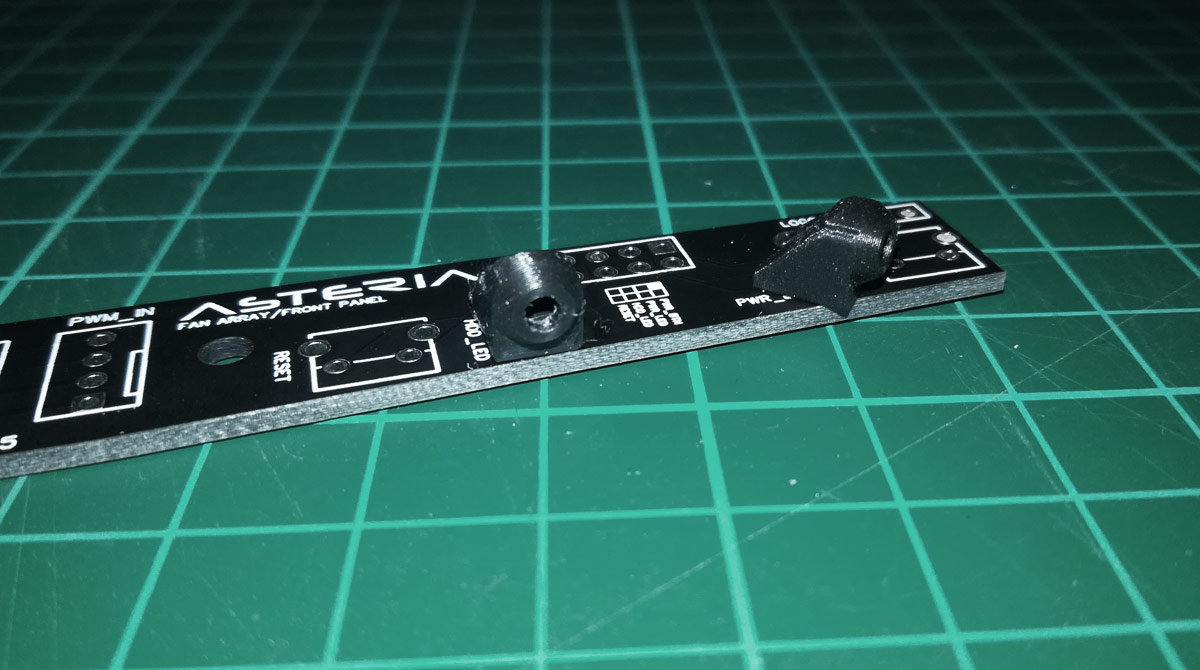
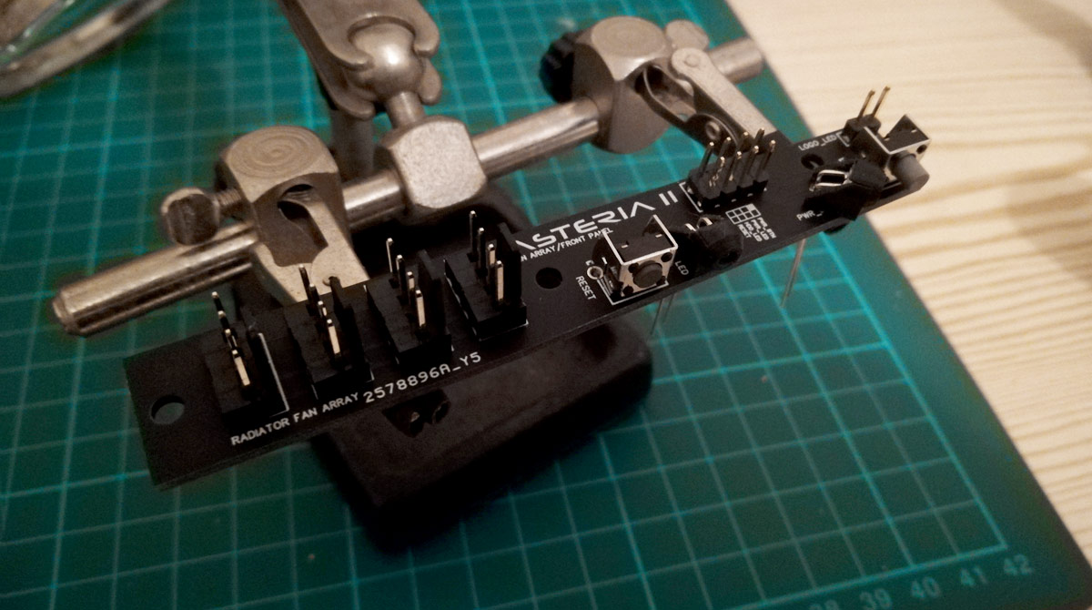
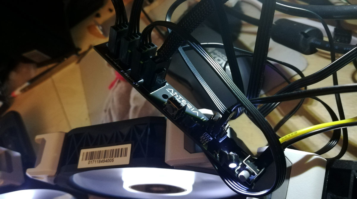
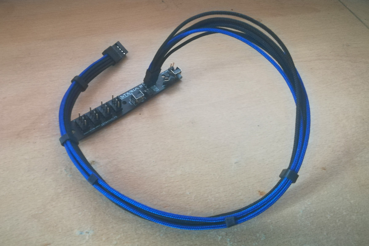
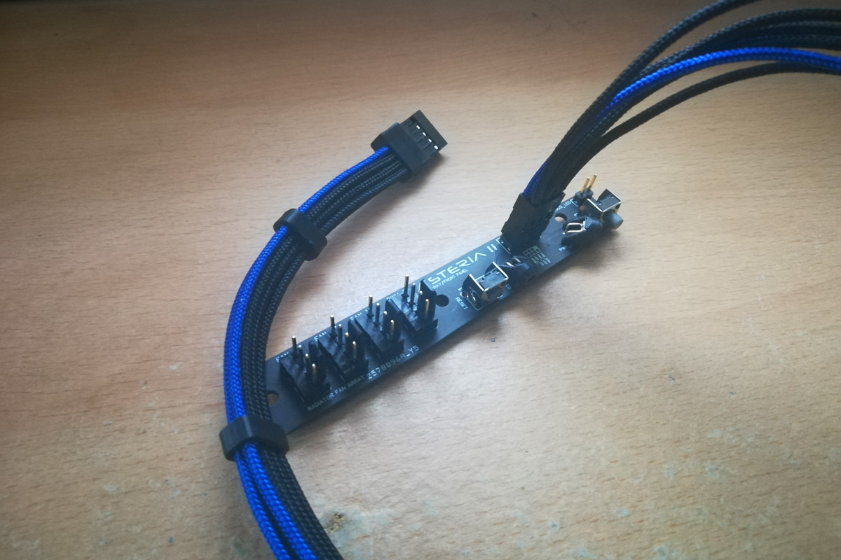
Combination front panel interface and PWM fan splitter
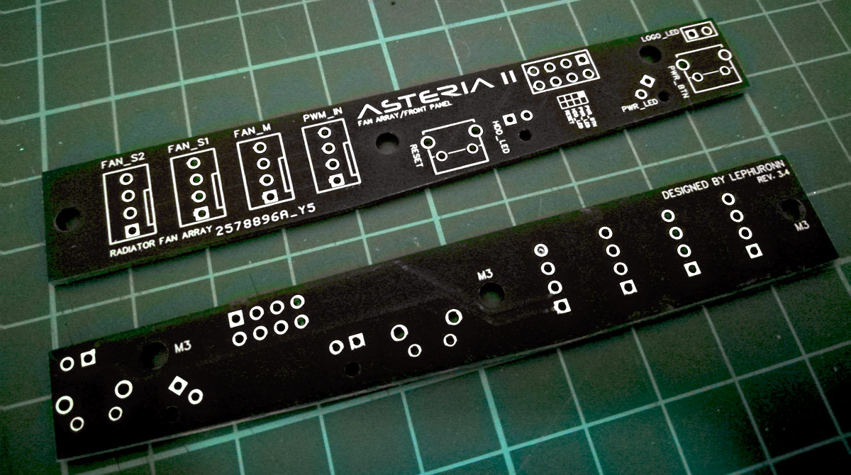
The rightmost fan header connects up to the Maximus VIII Impact's fan extension control board with the other 3 for the ML120s. There is also a 2-pin header on the very right edge sharing the 12V input for the fans which I'll be using for a tiny LED strip. Fortunately the fan extension control board is actively powered so I don't have to worry that 3 LED fans and a 12V LED strip will burn a motherboard header")
All laid out...
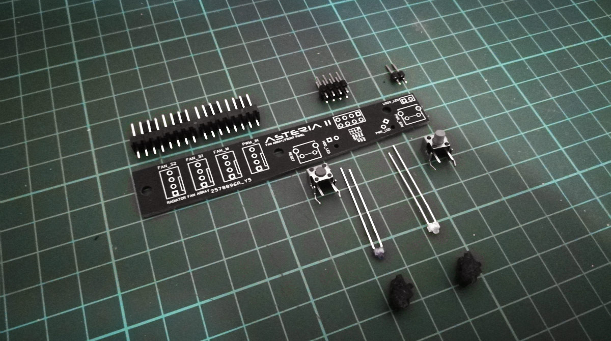
...with a pair of tiny holders for the 1.8mm LEDs, also designed and printed by moi.
4-way 12V splitter board, SATA powered
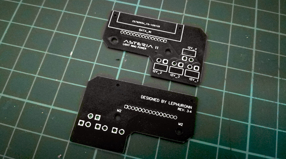
1mm thick PCB rather than 1.6mm as it's mounted to the back of the hard drive plate, so there's only 8mm gap until the motherboard. The odd shape is to wrap around some large surface components on the back of the motherboard.
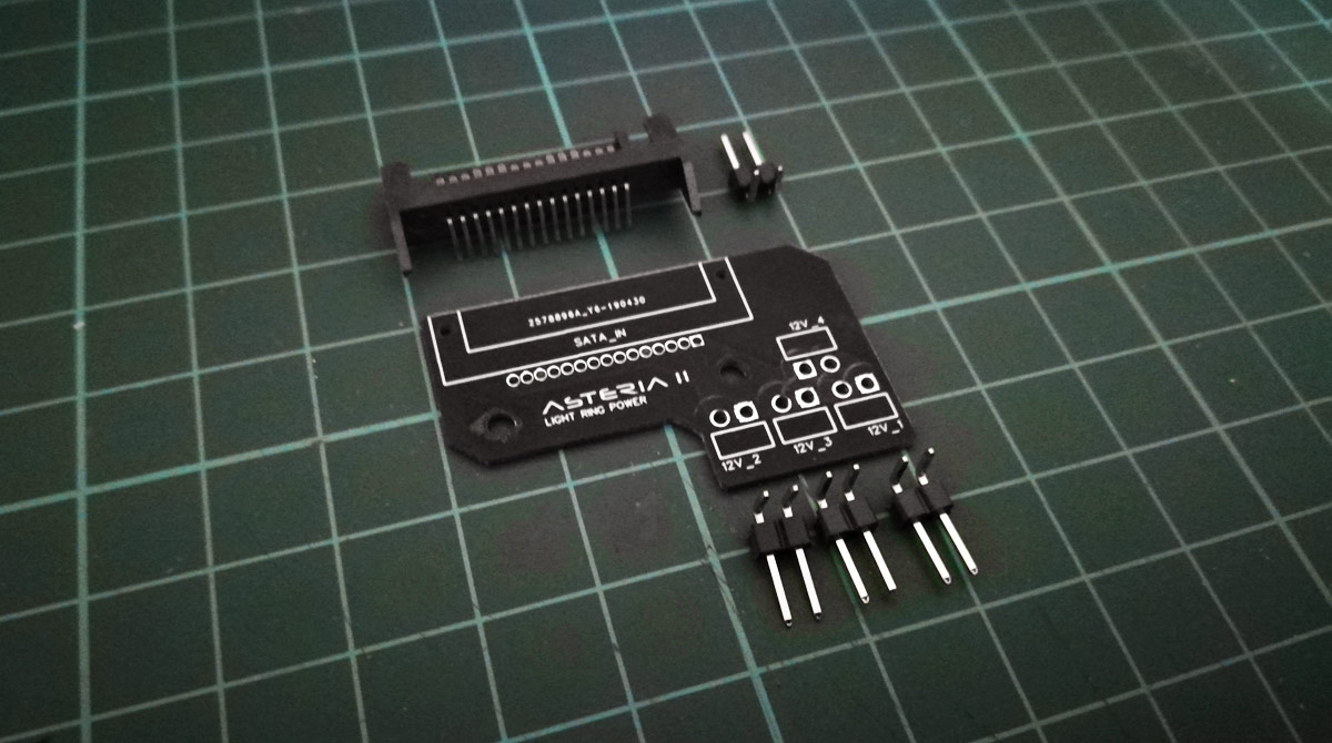
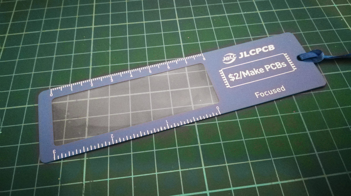
Made me chuckle that JLCPCB threw in a magnifying glass as their token gift because that SATA power has 15 pins at 1.27mm pitch! My eyes don't work that small.
So let's do this!
So, rejigging the case layout to accommodate the 360 radiator means there's no space to use the stock front panel connectors. The original plan was to veroboard some switches and LEDs together, but about 18 months ago (I know, I know) I thought "let's just go all-in with this project and make up everything custom I can". So out with the veroboard, in with some custom PCB design
If you're looking at doing PCBs, I strongly recommend EasyEDA. The online editor is just incredible for creating your circuit schematics, hooking in real manufacturing parts and generating PCB layouts with proper footprints. EasyEDA is in the same group as LCSC for components and JLCPCB for PCB manufacturing, so you have a one-stop-shop to design, make and populate your custom bits.
4-pin fan headers and SATA power I sourced elsewhere, but the EasyEDA editor allows you to create your own component footprints too, so I grabbed the Molex specs and drew up the missing parts.
And here we are! (Excuse the potato phone pictures, the room is very gloomy. Tidied up as best I can)
No extra charge for black board, no extra charge for simmer board thickness, and 5 boards for very little money if you stay within a 100x100mm footprint. Winner.
I know you're not going to see them once installed, but if Asus can put a ROG logo on their Thor PSU heatsinks then I can sure as hell brand my PCBs
Combination front panel interface and PWM fan splitter
The rightmost fan header connects up to the Maximus VIII Impact's fan extension control board with the other 3 for the ML120s. There is also a 2-pin header on the very right edge sharing the 12V input for the fans which I'll be using for a tiny LED strip. Fortunately the fan extension control board is actively powered so I don't have to worry that 3 LED fans and a 12V LED strip will burn a motherboard header
All laid out...
...with a pair of tiny holders for the 1.8mm LEDs, also designed and printed by moi.
4-way 12V splitter board, SATA powered
1mm thick PCB rather than 1.6mm as it's mounted to the back of the hard drive plate, so there's only 8mm gap until the motherboard. The odd shape is to wrap around some large surface components on the back of the motherboard.
Made me chuckle that JLCPCB threw in a magnifying glass as their token gift because that SATA power has 15 pins at 1.27mm pitch! My eyes don't work that small.
So let's do this!
Last edited:
Front panel and fan splitter
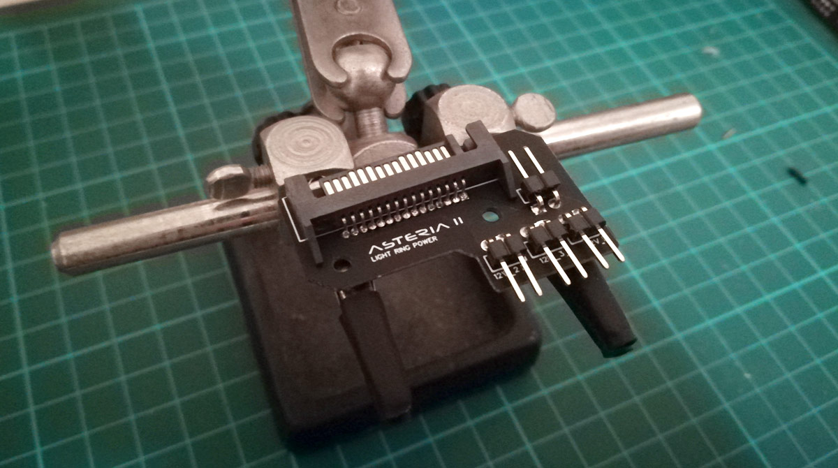
I'm usually really ham-fisted with small, delicate work, but I'm really quite proud of this solder job, especially as it's been almost a decade since I last picked up an iron. Too much solder here and there, but nothing that can't be cleaned up with some braid later on.
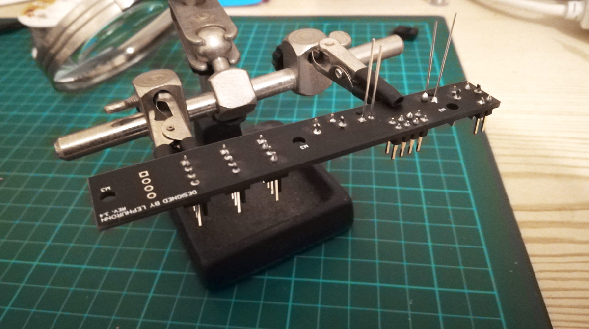
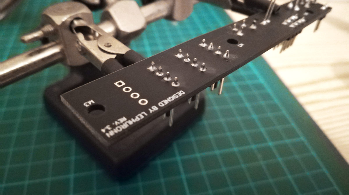
Gravity and through-hole soldering are an interesting combination, but complete nonetheless!
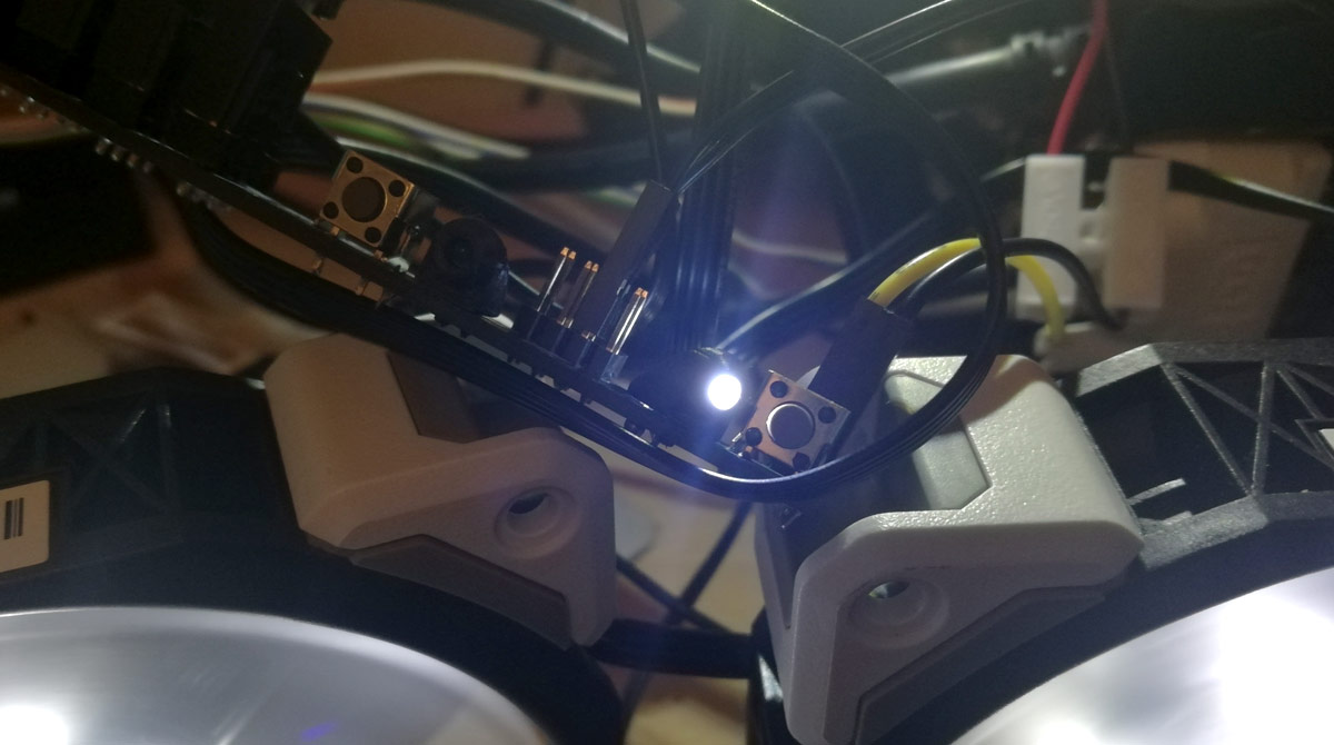
Those LED holders look ace I must say. In retrospect I should've allowed for the 45 degree overhang in the design, but they were enough of a pain to print correctly at a mere 6mm tall without doing rounded bases and whatnot. Now, do you remember this?
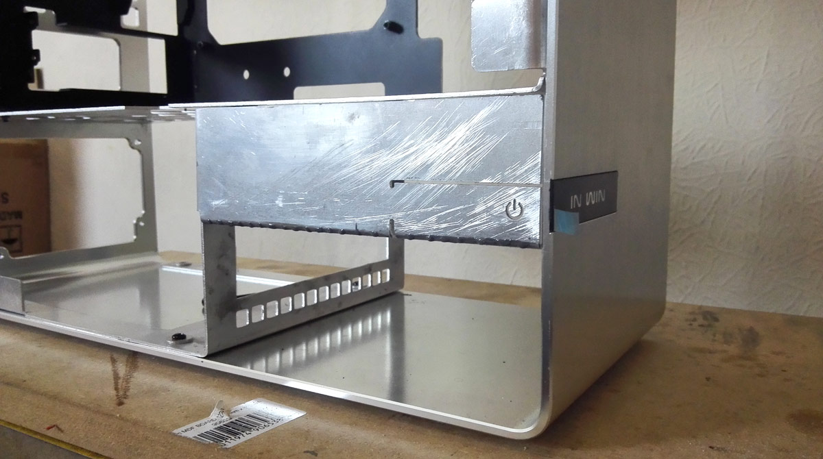
This is why I used a longer tactile switch at the end. The angle of the PCB and the recessed switch allow a few mm of movement for the aluminium tongue that forms the power switch. There will be a sliver of frosted or opal acrylic glued behind the power icon cutout which will just rest on the tactile switch. The 45 degree orientation of the LED then illuminates that acrylic sliver to give a nice glowy power icon when the system is running. Since nothing is assembled right now I don't have a picture, but a preliminary test works so very nicely.
Also, the black In Win logo strip is illuminated too on the stock case, so I'll be keeping that motif with a small LED strip wedged in somehow and powered by the 2-pin connector behind the power switch.
The other tactile switch and LED are reset and HDD activity, and it'll take a pin to activate that switch (by design though).
Anybody would think I actually planned all this out
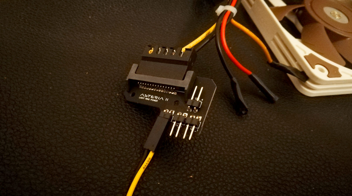
LED power splitter
I'll be honest in saying I made so much of a pig's ear of the SATA power I'm not going to show you so cute from above though.
4 connections for 4 light sources. The SSD covers and motherboard light ring will hook into the bottom 3 headers, with the 4th spare just in case. Likely to be a small light source above the motherboard to give a bit of flood fill, but we'll see closer to the time.
So all made up, but do they work?
I'm usually really ham-fisted with small, delicate work, but I'm really quite proud of this solder job, especially as it's been almost a decade since I last picked up an iron. Too much solder here and there, but nothing that can't be cleaned up with some braid later on.
Gravity and through-hole soldering are an interesting combination, but complete nonetheless!
Those LED holders look ace I must say. In retrospect I should've allowed for the 45 degree overhang in the design, but they were enough of a pain to print correctly at a mere 6mm tall without doing rounded bases and whatnot. Now, do you remember this?
This is why I used a longer tactile switch at the end. The angle of the PCB and the recessed switch allow a few mm of movement for the aluminium tongue that forms the power switch. There will be a sliver of frosted or opal acrylic glued behind the power icon cutout which will just rest on the tactile switch. The 45 degree orientation of the LED then illuminates that acrylic sliver to give a nice glowy power icon when the system is running. Since nothing is assembled right now I don't have a picture, but a preliminary test works so very nicely.
Also, the black In Win logo strip is illuminated too on the stock case, so I'll be keeping that motif with a small LED strip wedged in somehow and powered by the 2-pin connector behind the power switch.
The other tactile switch and LED are reset and HDD activity, and it'll take a pin to activate that switch (by design though).
Anybody would think I actually planned all this out
LED power splitter
I'll be honest in saying I made so much of a pig's ear of the SATA power I'm not going to show you
so cute from above though.
4 connections for 4 light sources. The SSD covers and motherboard light ring will hook into the bottom 3 headers, with the 4th spare just in case. Likely to be a small light source above the motherboard to give a bit of flood fill, but we'll see closer to the time.
So all made up, but do they work?
Last edited:
Testing it all
First test is the easy one. Knowing I'll only need the 12V supply, and I was likely to make a mess of the SATA power soldering, there are no traces for the 5V and 3.3V pins in the PCB, essentially giving myself breathing space if solder crosses over the connections. Also I can use the ground wire furthest from the 12V wire to avoid any short-circuiting there.
Hooked up
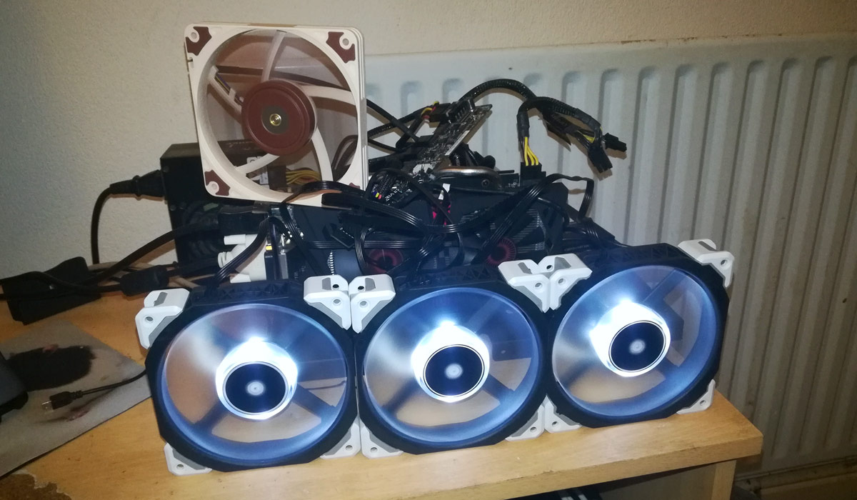
Sacrificial PSU, sacrificial motherboard (because I've lost my jump starter, don't have paperclips and don't have male ATX crimps to make one), Noctua fan to load the 12V rail, hit the switch and...
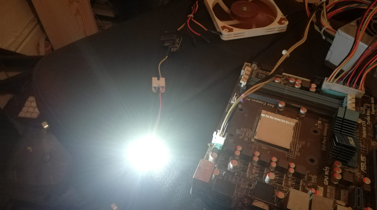
Success! Bright, blinding, flaring success!
I shan't put up another 3 pictures of the same blinding light, but suffice it to say all 4 headers work like a charm.
The bigger test is the fan splitter. Initial load works perfectly.
Full power going to the LED strip, nice and bright LED to glow that power icon. Didn't let it run for long as all that's coming off a single fan header on the motherboard
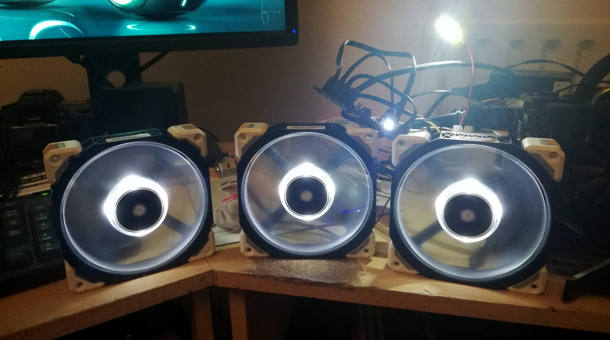
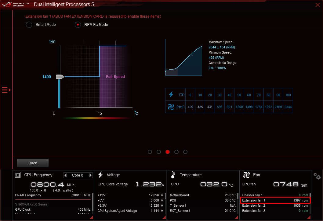
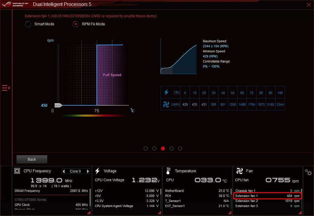
The crunch comes tying everything together with the Asus fan extension card. I'm going to use the CPU fan header purely to monitor pump speed, so the 4 radiator fans will come off the extension card, and in turn one of those channels will drive the fan splitter so the 3 ML120s all work in unison.
So let's set up a rat's nest of cables and boards.
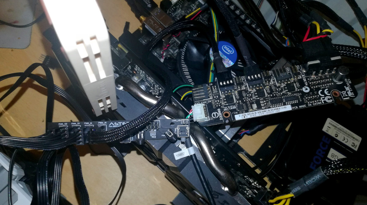
The chunky braided cable is female-female PWM fan cable coming off port 1 of the extension card and into the fan splitter for the trio of ML120s on the 360mm radiator. Port 2 will drive a Noctua NF-A12x15 sat on the single 120mm radiator. There will also be a Barrow temperature probe hooked into the extension card too.
Excellent!
And a quick test with the horrendous Asus Fan Xpert shows the ML120s reporting their RPM correctly and fully controlled through PWM.

So, that's the PCBs covered in this neverending build log. Next up is to measure wire lengths for the proper fan cable and the front panel connectors and get those cable looms made up.
Thanks for reading as always, stay safe and wash your damn hands
Back soon
First test is the easy one. Knowing I'll only need the 12V supply, and I was likely to make a mess of the SATA power soldering, there are no traces for the 5V and 3.3V pins in the PCB, essentially giving myself breathing space if solder crosses over the connections. Also I can use the ground wire furthest from the 12V wire to avoid any short-circuiting there.
Hooked up
Sacrificial PSU, sacrificial motherboard (because I've lost my jump starter, don't have paperclips and don't have male ATX crimps to make one), Noctua fan to load the 12V rail, hit the switch and...
Success! Bright, blinding, flaring success!
I shan't put up another 3 pictures of the same blinding light, but suffice it to say all 4 headers work like a charm.
The bigger test is the fan splitter. Initial load works perfectly.
Full power going to the LED strip, nice and bright LED to glow that power icon. Didn't let it run for long as all that's coming off a single fan header on the motherboard
The crunch comes tying everything together with the Asus fan extension card. I'm going to use the CPU fan header purely to monitor pump speed, so the 4 radiator fans will come off the extension card, and in turn one of those channels will drive the fan splitter so the 3 ML120s all work in unison.
So let's set up a rat's nest of cables and boards.
The chunky braided cable is female-female PWM fan cable coming off port 1 of the extension card and into the fan splitter for the trio of ML120s on the 360mm radiator. Port 2 will drive a Noctua NF-A12x15 sat on the single 120mm radiator. There will also be a Barrow temperature probe hooked into the extension card too.
Excellent!
And a quick test with the horrendous Asus Fan Xpert shows the ML120s reporting their RPM correctly and fully controlled through PWM.
So, that's the PCBs covered in this neverending build log. Next up is to measure wire lengths for the proper fan cable and the front panel connectors and get those cable looms made up.
Thanks for reading as always, stay safe and wash your damn hands
Back soon
Last edited:
Soldato
- Joined
- 28 Dec 2017
- Posts
- 9,287
- Location
- Beds
You don't **** about! Custom electronics is very satisfying to see, I haven't made PCBs yet but I'm a chronic strip board user
Thanks to you all for the comments.
Good to have you here.
I'll be honest, if I could wedge a tactile switch into 2.54mm pitch stripboard then I wouldn't have done these PCBs. The LED power splitter would've been fine with some carefully loomed Y cables too. But I'm all about clean and precision with everything I do (even if I fail to actually implement it ) so PCBs were always on the cards. I'm glad I've done them now.
I thought you might like this post given your musing about multimeters and RGB controllersOhh electronics!! Subbed and much later than your sub to mine!
Good to have you here.
By virtue of this build log starting in 2016 I'd say I do **** about quite a lotYou don't **** about! Custom electronics is very satisfying to see, I haven't made PCBs yet but I'm a chronic strip board user
I'll be honest, if I could wedge a tactile switch into 2.54mm pitch stripboard then I wouldn't have done these PCBs. The LED power splitter would've been fine with some carefully loomed Y cables too. But I'm all about clean and precision with everything I do (even if I fail to actually implement it ) so PCBs were always on the cards. I'm glad I've done them now.Cheers dude, I must say JLCPCB changed their product offering at just the right time. When I was designing these things, there was a premium for anything other than green PCBs. When I came to pull the trigger they were offering all colours (including PURPLE @Vince ) as standard.Very nice. Don't think I've seen custom PCBs outside your thread. Definitely gives it a more professional look.
Not had a compliment quite like that in a looooong timeThis is the build log equivalent of Edging. You may make us wait - but those are excellent moneyshots.
If this turns out half as well as I think (and hope) I think we're all going to spaff our britches at the very end.
Cheers dude, I must say JLCPCB changed their product offering at just the right time. When I was designing these things, there was a premium for anything other than green PCBs. When I came to pull the trigger they were offering all colours (including PURPLE @Vince ) as standard.
Ahh man I almost have to find something to make one for now!!!
I'm sure you'll find something
I think the problem is with that one i'm building is that I don't want to spend that much on it hence the cheap Chinese parts. Having already spent around £450 on that rig i'm reluctant to spend much more. Is going to be a capable machine for the money but really if im going to go nuts on something ill do it on my next Threadripper build when I need to update my current one.
To all you lovely folks following this log, do me a favour: the next time I even think "individually-sleeved, hetshrinkless front panel cables" somebody please shoot me. What an utter ballache this was!
2mm matte black and electric blue paracord connecting a single 10-pin Dupont I robbed from an Asus Q-Connect adapter for the motherboard and an 8-pin for the front panel PCB.
3D printed a few combs too mainly to help training because paracord isn't very rigid even at maximum stretch, as well as a fiddly end cap for the motherboard end to hide 1 or 2 over-melted paracord ends
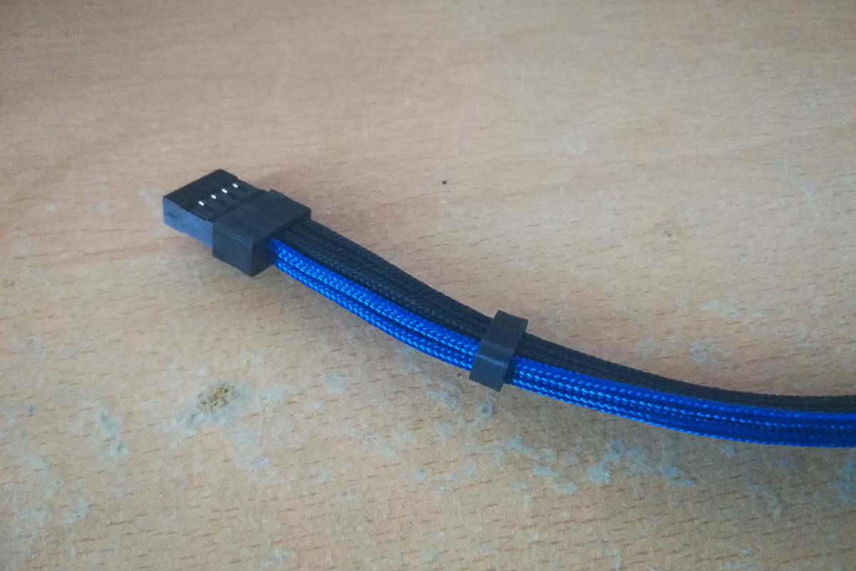
Not going to comb all the way down as there is an awkward twist to the wires as my PCB pinout is wildly different from the motherboard pinout. Also need a bit of give as I stuff the PCB end into the case and wrap around the front of the 360mm radiator.
Utter pain, took a few attempts to get my technique down, but ultimately very happy!
2mm matte black and electric blue paracord connecting a single 10-pin Dupont I robbed from an Asus Q-Connect adapter for the motherboard and an 8-pin for the front panel PCB.
3D printed a few combs too mainly to help training because paracord isn't very rigid even at maximum stretch, as well as a fiddly end cap for the motherboard end to hide 1 or 2 over-melted paracord ends
Not going to comb all the way down as there is an awkward twist to the wires as my PCB pinout is wildly different from the motherboard pinout. Also need a bit of give as I stuff the PCB end into the case and wrap around the front of the 360mm radiator.
Utter pain, took a few attempts to get my technique down, but ultimately very happy!
Last edited:
You'd not worked out from all the (implied) colourful language on my thread that this was going to be a pain?! I must try harder!
Looks nice though. So this is the 425 paracord you mentioned then?
Can you feel the hate for your 3D printing? You'll have to excuse me, I've been watching a maker, developing a kit I want to build-along and every few minutes it's "...and I needed a <thing> so I 3D printed THIS ... and it's perfect". After a while the mere mention of a 3D printer has you foaming at the mouth!
Looks nice though. So this is the 425 paracord you mentioned then?
Can you feel the hate for your 3D printing?
You'll have to excuse me, I've been watching a maker, developing a kit I want to build-along and every few minutes it's "...and I needed a <thing> so I 3D printed THIS ... and it's perfect". After a while the mere mention of a 3D printer has you foaming at the mouth!