lol I knew before you even started your cables paracord was going to be a pain, which is why I asked about your stretching and slipping experience ")
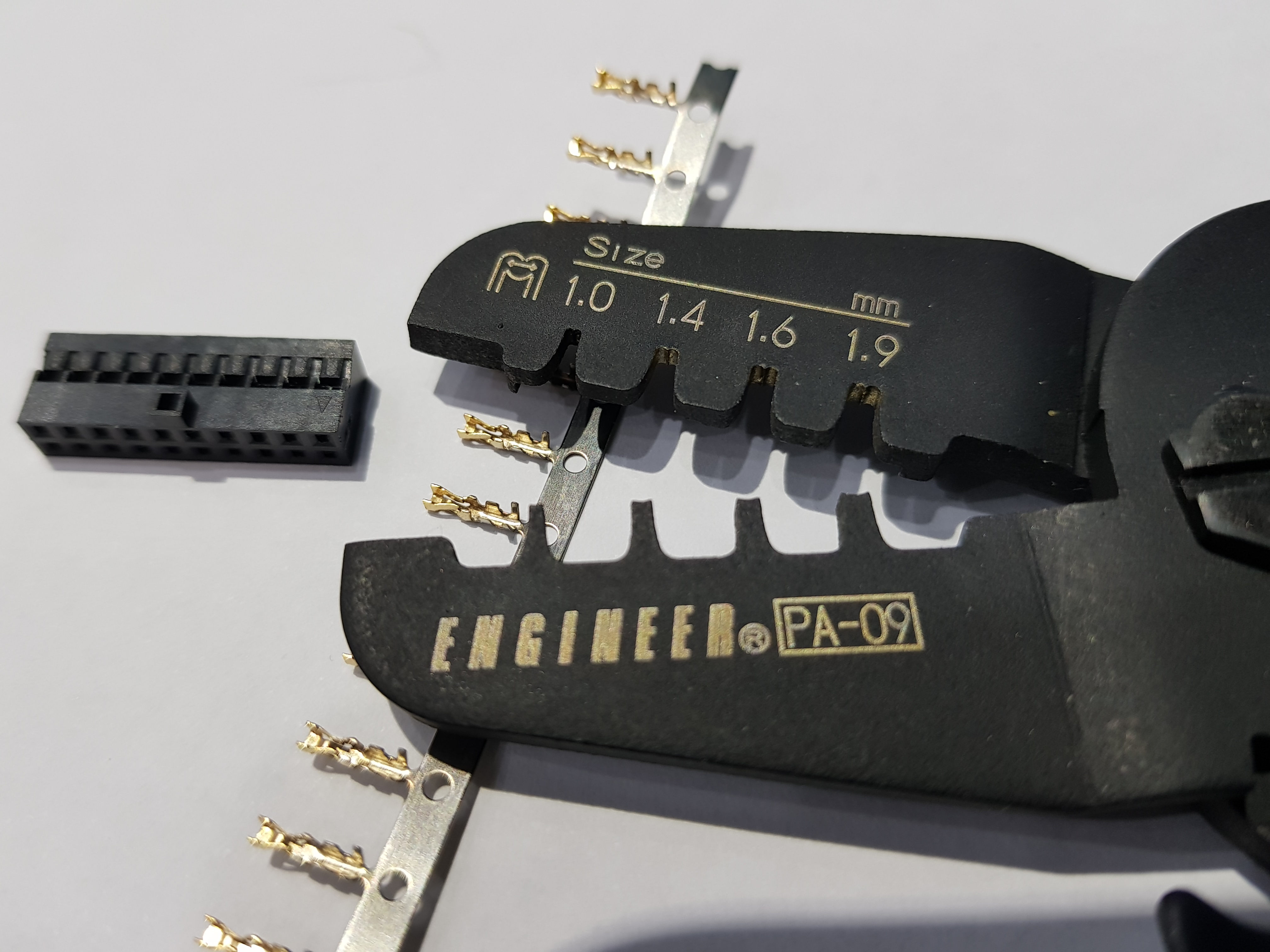
The black is the 425 paracord I mentioned; it's 3mm thick when the cord is inside, but shrinks to a smidge over 2 when fully stretched over my 1.1mm OD wire. The original wire I was using was 1.3mm OD but I had a few issues getting decent crimps on my Dupont connectors (a bit too wide to fit the housing). The blue is actually 275 paracord at 2.4mm wide because i knew I was reducing the OD of the wire. Fortunately it too drops to 2.1mm when fully stretched so both completed wire colours end up being the same OD.
Don't hate on my printing, however much I love my Ender 3 Pro it's stopped being dimensionally accurate when printing tiny things, so it took a chunk of trial and error to get my combs and caps correct Other than this recent glitch though, my printer has been top banana since the day I got it, so I've avoided a lot of the kit printer headaches.
The black is the 425 paracord I mentioned; it's 3mm thick when the cord is inside, but shrinks to a smidge over 2 when fully stretched over my 1.1mm OD wire. The original wire I was using was 1.3mm OD but I had a few issues getting decent crimps on my Dupont connectors (a bit too wide to fit the housing). The blue is actually 275 paracord at 2.4mm wide because i knew I was reducing the OD of the wire. Fortunately it too drops to 2.1mm when fully stretched so both completed wire colours end up being the same OD.
Don't hate on my printing, however much I love my Ender 3 Pro it's stopped being dimensionally accurate when printing tiny things, so it took a chunk of trial and error to get my combs and caps correct
Other than this recent glitch though, my printer has been top banana since the day I got it, so I've avoided a lot of the kit printer headaches.