(In Win 901) Asteria II: Rearmoured

Soldato
OP
Joined
26 Sep 2010
Posts
7,146
Location
Stoke-on-Trent
Pics look very good for a phone.
The phone's bolstered by having proper studio lights, but the ISO range is artificial and limited so it's almost impossible to get decent results shooting black on black. Resisted temptation to cheat and clean them up in Photoshop though.

I hate to disagree, but it's more backplate pr0n than naked GPU pr0n! :D
To be honest, naked PCB shots felt almost obligatory because all the watercooling logs like to flash the GPU without her clothes on, but I agree with your disagree and that backplate has ended up pure sex!

Last set presumably are Asteria's [Emperor's] New Clothes!

Well, this is Asteria II: Rearmoured ;)


Glad you like dude!
 
Soldato
OP
Joined
26 Sep 2010
Posts
7,146
Location
Stoke-on-Trent
asteria2_banner.jpg


Hello my lovelies, it's been a while. I have a bit of time off work so I can crack on with the guts of this project. Now that I have tangible progress and photographic evidence of my sheer perfect execution and all the mistakes I never made, I am happy to say it's time for me to walk you through the actual case work :D

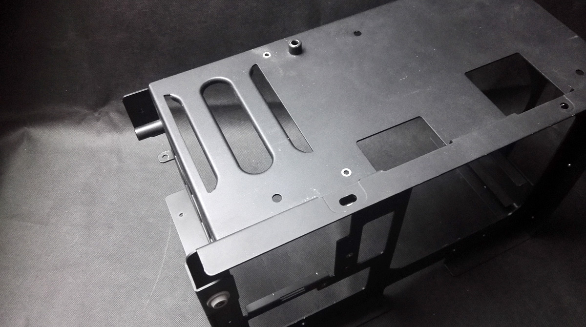
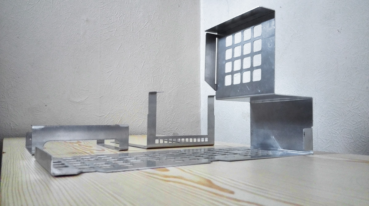
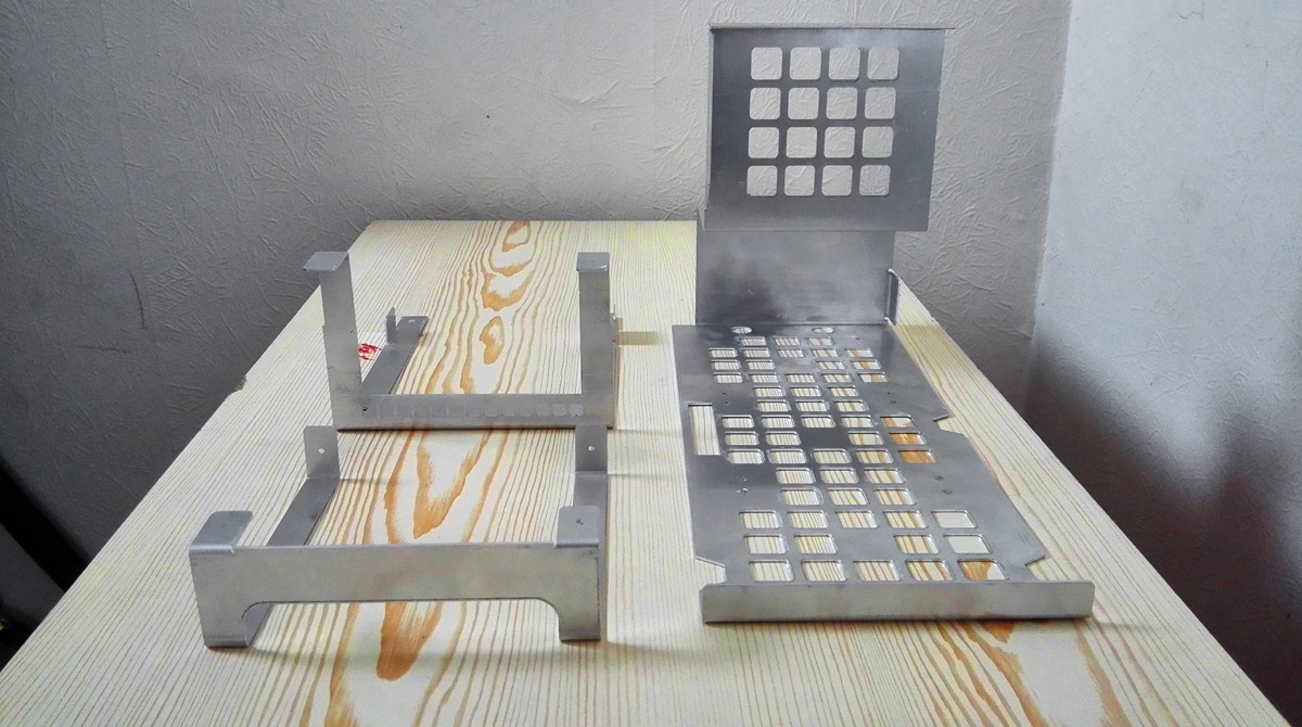
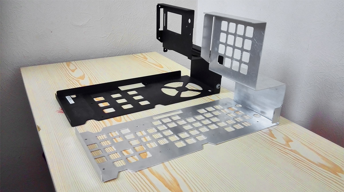
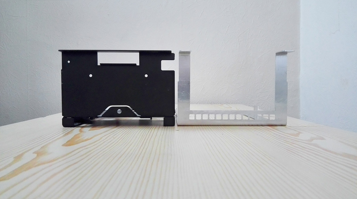
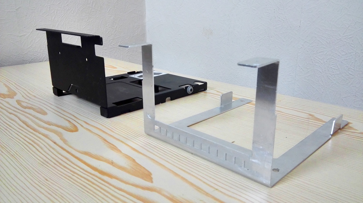
Quick shots of the 3 core structural pieces:
structural_full-2.jpg

structural_full-1.jpg


Laser cut 1.5mm aluminium and (eventually) folding into shape.

I've said before that a core design choice for this project was to retain as much of the stock look of the In Win 901 as possible, despite the extensive modifications made to the interior. Part of the way to achieve that is using the same thickness of aluminium and to form the structure through folding larger cut pieces just as in Win do. That's meant replicating fiddly tabs for using existing rivet holes, creating seemingly superfluous bits to accommodate mount points and support for the glass panels. Rough sketches to finished laser cut pieces was about 8 months in the end, with a lot of chopping, changing and procrastinating!

Bit of history
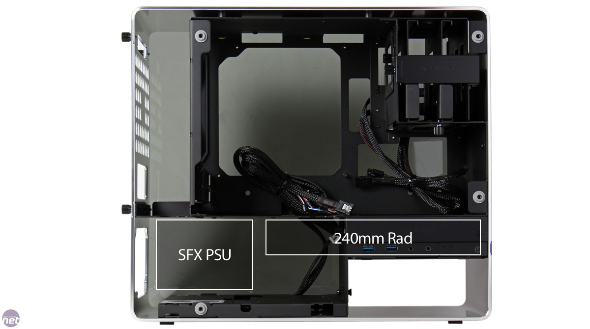
As I said at the very start of this log, Laine's "Clarity" project was an impressive piece of work fitting a full loop into the 901, but I wasn't enamoured with some aspects of how he achieved it, specifically the use of a pair of 120mm radiators in the bottom. Since he chopped up good chunks of the existing case, I couldn't understand why he just didn't punch through the bottom body and slide a 240mm rad in, and avoid the complications of lining them up to be level, tubing runs between the two and whatnot. After delusions of grandeur and a couple months staring at pictures and Photoshop measurements, I had a special offer land in my email for the 901 in silver at a good discount. It was my birthday too so I pulled the trigger to see what I could do with it.

Sure enough, there was plenty of space to fit a 240mm rad in the bottom and switch over to a SFX PSU down there too - having run a GTX Titan in a Sugo SG05 for a few years I really didn't see the point of full ATX PSUs in Mini ITX cases. All that was needed was to make a large cutout area above the optical drive and lose the 120mm fan intake area.

old-concept.jpg

(Credit to bit-tech for the original photo)

I had a bit of a revelation though which changed the scope of this project; rather than refining what Laine had done I was going to try to take it up another level. Conceptually of course :p there's no way I can touch that man's craftsmanship.
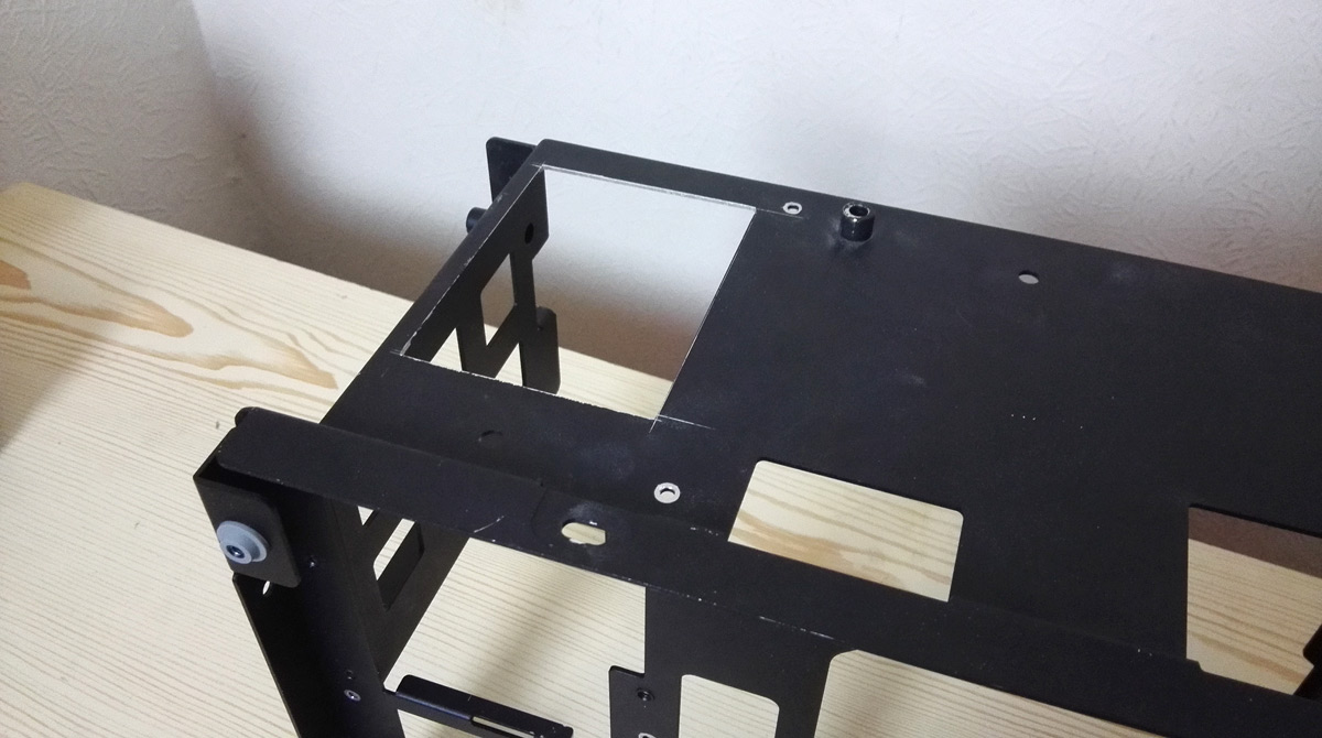
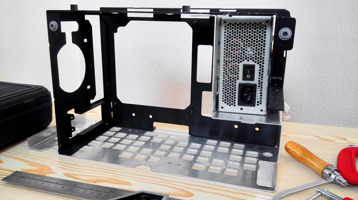

Main Body
When I realised the existing 901 floor couldn't be re-purposed for decent radiator holes I had the idea of designing an entirely bespoke body. Still wanting to keep the same layout I measured up all the folds for the hard drive area and it struck me that the space In Win had created was pretty close to the size of a SFX PSU. I hadn't used 3.5" drives for a while, and moving the PSU up to the top-right would free up 100mm of space in the lower chamber.

Bam, there it was: 
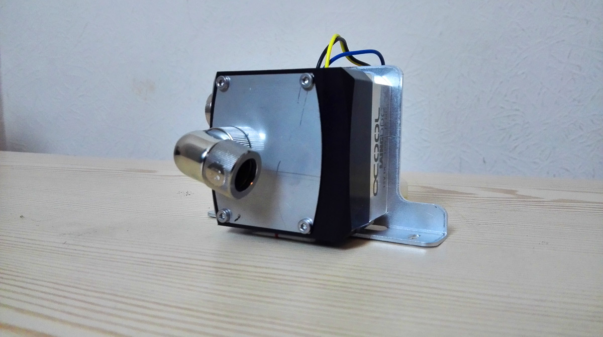
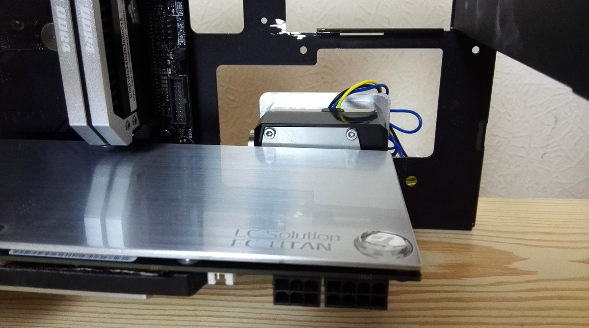
let's raise the stakes and go 360mm radiator at the bottom. Took a while to find a rad that would work, but ultimately went for the Alphacool UT60 360 as it's the perfect width to not foul on the PSU cutout in the outer skin and has a plug on the back I could use as a drain port. Messing around with sealing the front ports with Fernox LSX is a story for another time ;) 
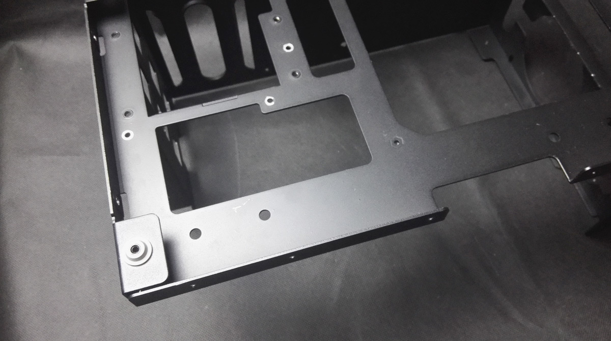
but with position confirmed I designed a new body to fit the UT60 and SFX PSU up top.
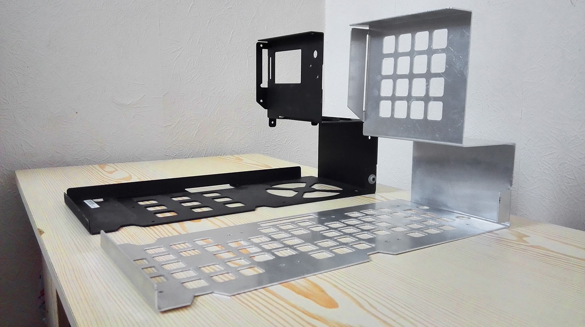
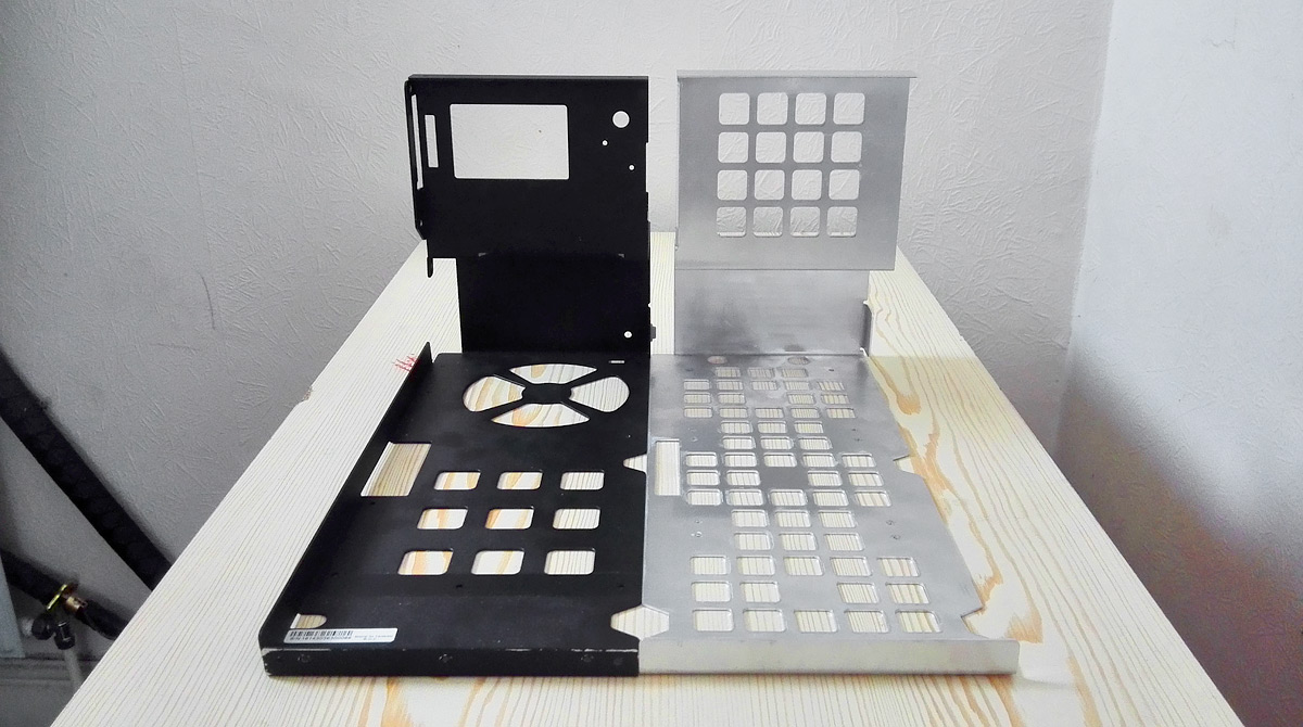
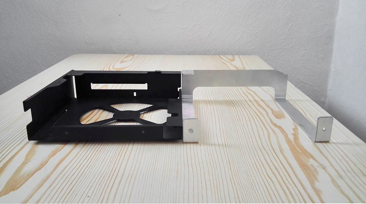
Old vs New
structural_body-perspective-1.jpg

structural_body-perspective-2.jpg


Replicated the tab on the upper section for extra support, and that damn fiddly tab on the bottom-right because the glass side panel has a mount there.

As you can see, there was no way I could re-purpose the existing fan and PSU holes for a radiator, especially as some of the actual screw positions wouldn't have any material above them.
structural_body-length.jpg


In Win do have a nice square grid design in parts of the case, so I kept that style going for the rad and PSU holes. Also copied the cutouts to get to mounting screws in other parts of the case. Trying to keep things looking stock, remember?
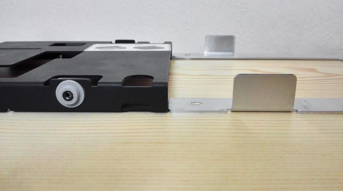
Old HDD vs New PSU
structural_body-psu-side.jpg

structural_body-psu-depth.jpg


Dropped down and pulled in but not a million miles away from the original.
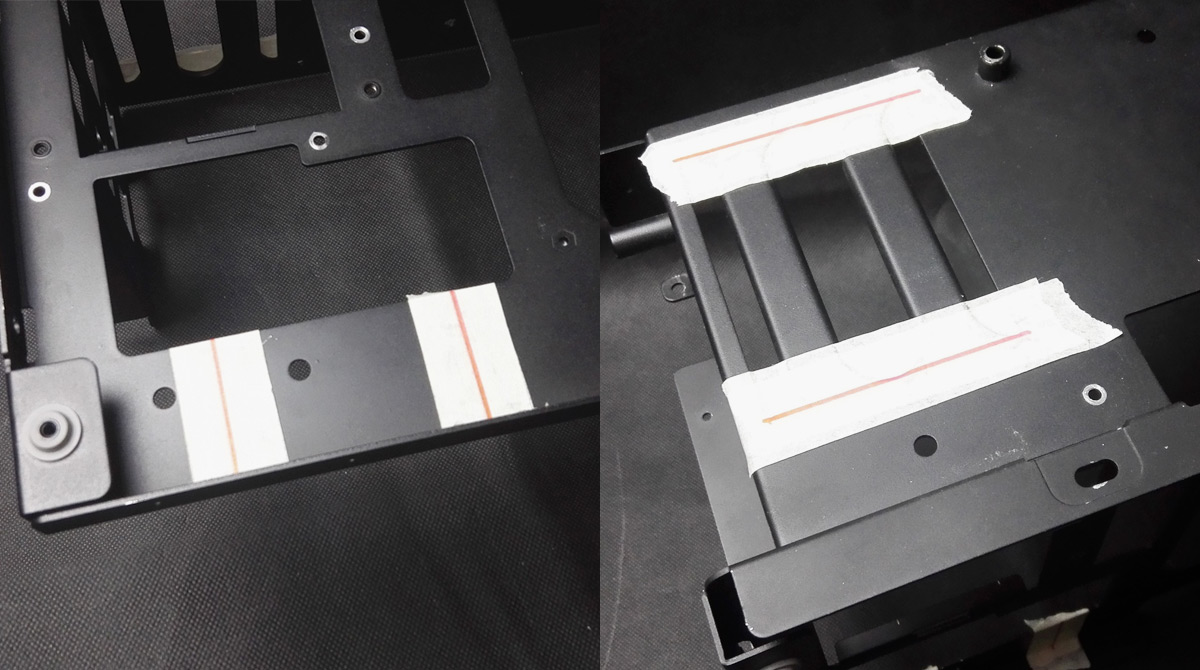
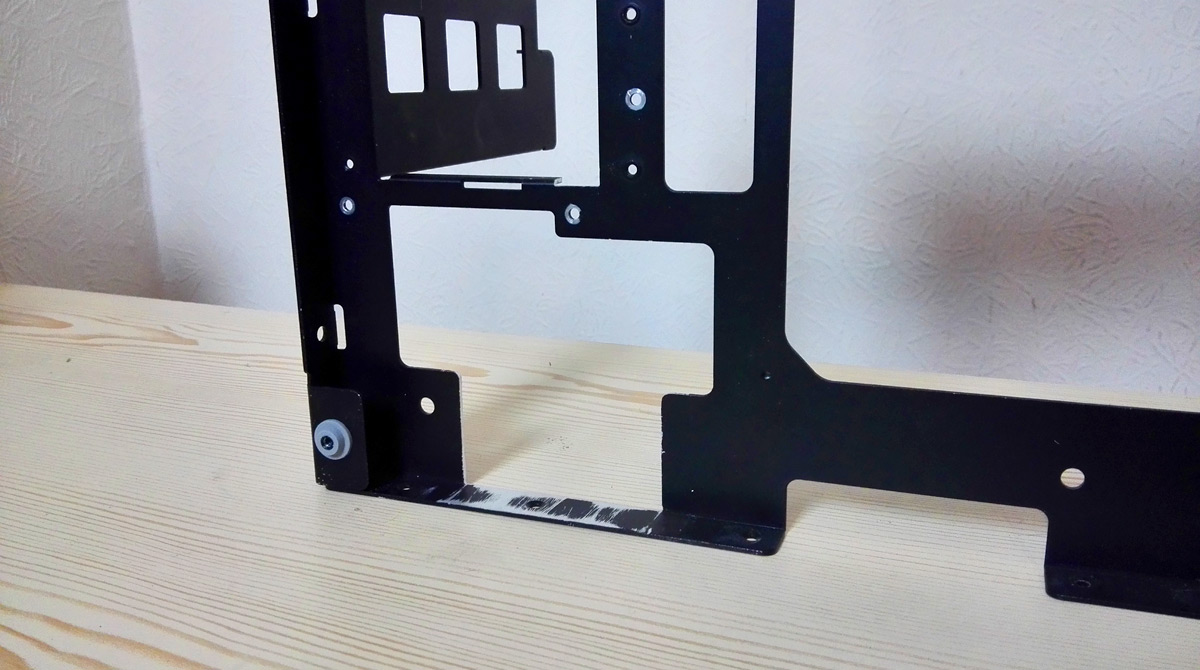
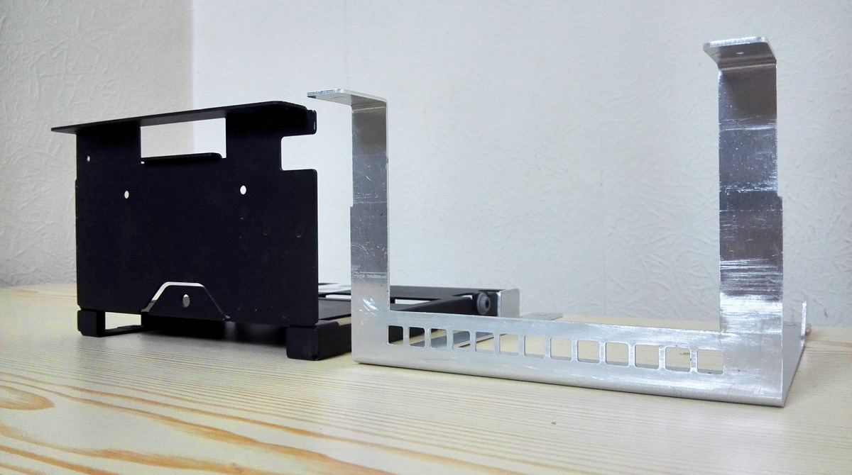

Lower "L" portion
Might as well design a bespoke piece for the lower compartment too, rather than chopping up the stock case!
structural_lower-l-pair-1.jpg

structural_lower-l-front.jpg


Again, square hole pattern for some intakes. To be honest you couldn't chop enough out of the original piece and still look tidy, certainly not with a 60mm thick rad (could that be the reason Laine didn't bother himself? :p )

(although there was a time it wasn't going to be square holes :p )
hole-faces.png


The stock case has some wonderful construction going on down here with hiding a slimline optical drive underneath the PSU, all folded from a single piece. I don't need all of that, but it's a shame to dump something so impressive.
structural_lower-l-pair-2.jpg


I do need something for the glass side panels to attach to, and lo and behold there's 2 tabs needed.
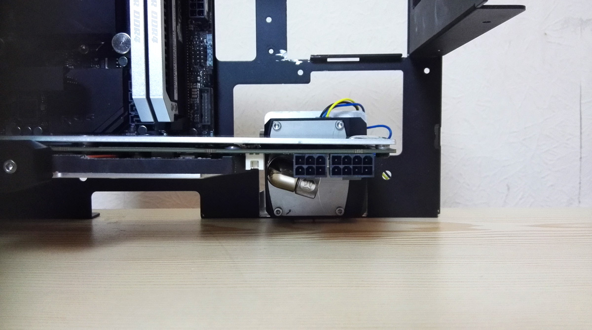
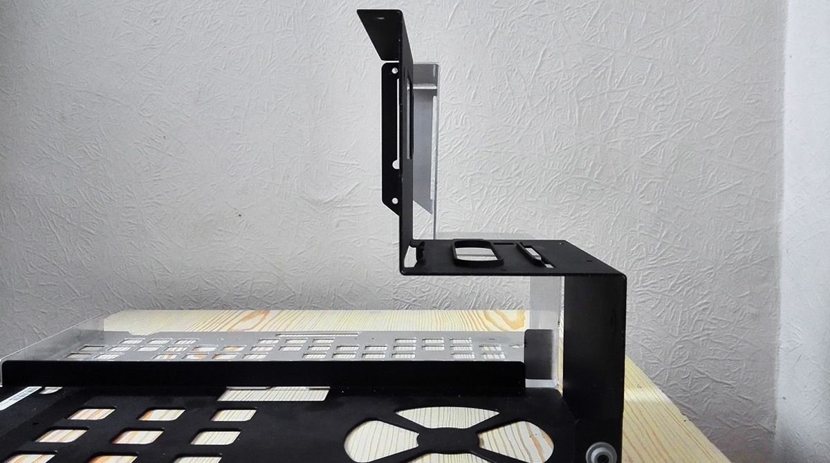
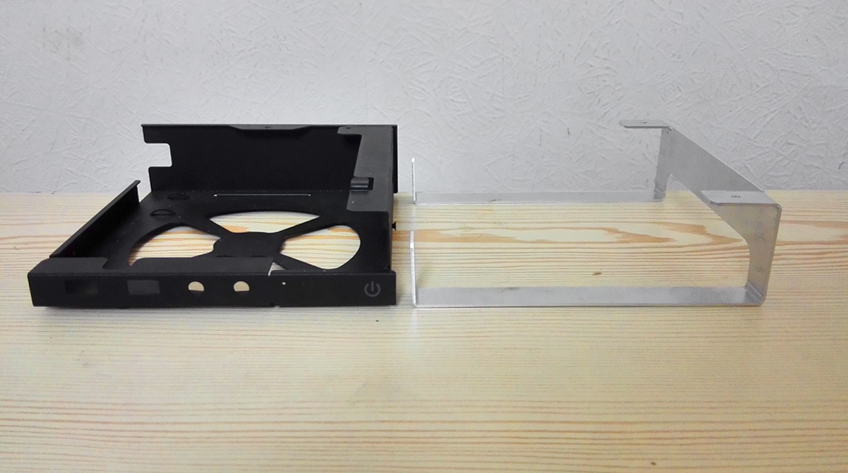
structural_lower-l-tabs.jpg


Fan assembly
Well, I call it a fan assembly purely because that's where the front 120mm intake would go. For me it's just a couple of strips! Crazy comparison time
structural_fan-front.jpg

structural_fan-side.jpg


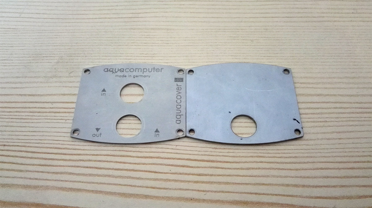
It's a purely functional piece to be fair. Power switch and activity LEDs will be strapped to it, but unfortunately there's not enough space between the edge of the case and the radiator to fit any sockets and cables to keep the I/O, so a pair of blanking plates will get bolted on to cover the space.

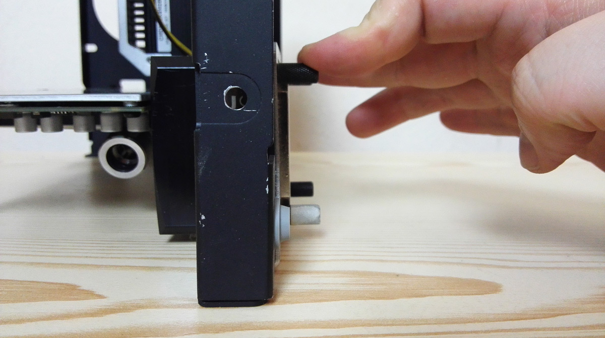
The stock power button is actually a nice tongue of springy aluminium that just rests on a tactile switch. I have a blanking plate variation cut which will hopefully replicate that look.


So there you go, a first proper post talking about the actual case work and design motivations for the project, and hopefully a slightly clearer picture of how the loop is going in.

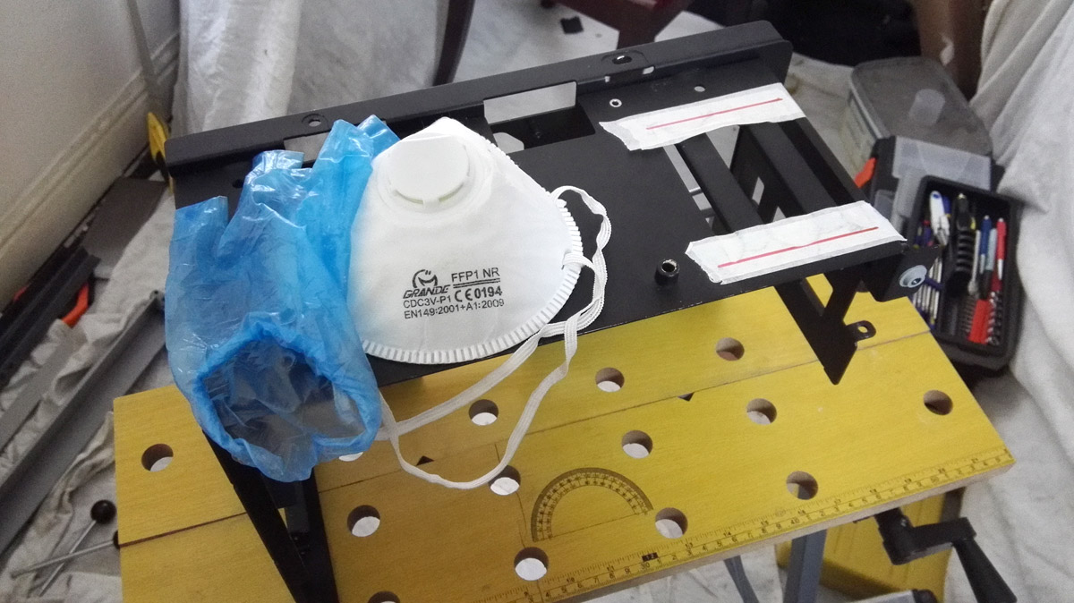
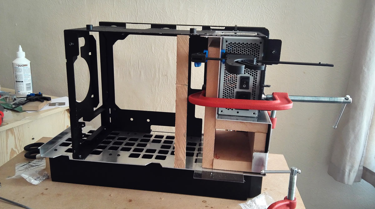
Next step is to get everything trued up a bit as a lot of the 90 degree angles have slipped a touch and to map out and drill all the holes I need to rivet and screw this thing together. There's still some chopping required on the case parts I'm keeping to ensure all this goes together correctly (which has already started), so hopefully I can sort that soon and give you another update.

Hope you enjoyed the read, back soon!
 
Last edited:
Soldato
Joined
4 Jun 2007
Posts
2,617
Location
Watford, UK
Looking good dude...or should I say "my lovely" ;)
Nice work on keeping it ...well, in keeping. And keeping your sanity intact is a feat in itself....or is that an erroneous presumption? :p

Looks like the finished product should he something to be proud of!
 
Soldato
OP
Joined
26 Sep 2010
Posts
7,146
Location
Stoke-on-Trent
I've not gone mental just yet, but it's be incredibly trying getting to this point. I was under no illusions that it would be simple, especially given the scale of my very first project, but I never expected some of the problems I've encountered. Fortunately I've been able to correct or conceal everything that's gone wrong.

The biggie was the Lower L piece given that it was designed to be form fitting around the radiator and all nice and symmetrical, but the bend radius that I was assured wouldn't be there threw all vertical measurements up by about 3mm meaning the rad and fans wouldn't even fit any more. Having already junked the back-ups I had to take a hacksaw to my remaining piece that had already been folded incorrectly twice and was fragile. It's turned out fine, but I have a sneaky feeling I may need to trim off even more. It may look fine to the 3rd person, but knowing it's wildly off what I intended and designed is going to bug me big time.

Still have to true all the bends so I can be accurate with the bazillion holes I need to map and drill. I am enjoying it but I'll be very glad when the structural stuff is done!
 
Soldato
OP
Joined
26 Sep 2010
Posts
7,146
Location
Stoke-on-Trent
I believe this is how murdermods started out :)

need to batch produce this plate after your build :D

But did Charles start out as ridiculously gammy-handed as me? If he did then there's hope for me yet! :D

Had I not burned through all of my spare pieces, I was very tempted to ask In Win for a black version and build a twin. I may still do so and tweak a few bits to allow for the bend radius this time.
 
Soldato
Joined
1 Dec 2015
Posts
18,514
But did Charles start out as ridiculously gammy-handed as me? If he did then there's hope for me yet! :D

Had I not burned through all of my spare pieces, I was very tempted to ask In Win for a black version and build a twin. I may still do so and tweak a few bits to allow for the bend radius this time.

spoke to inwin once or twice, american team is a lot nicer and throw stuff at users but cant ship to the UK :(
 
Soldato
OP
Joined
26 Sep 2010
Posts
7,146
Location
Stoke-on-Trent
In Win UK were happy to give me vectors of their logo and expressed an interest in showcasing this when it was further down the line as they couldn't work out where the 360 rad was going. Once this is a bit further along I'll give them a poke and see what they think.
 
Soldato
OP
Joined
26 Sep 2010
Posts
7,146
Location
Stoke-on-Trent
Hello hello!

Given the positive response this project has received so far across the interwebs, I thought it was about time to share the first actual failure, and it's kinda big, kinda not.

The main body part of the case I'm keeping needs a few cuts to remove unneeded tabs, awkward flanges and space making for my pump. Funny really, part of the reason for designing entirely new sections of the case was to avoid chopping up irreplaceable parts, but hey ho, the needs must!

(I wonder if B Negative has thrown his 901 innards out for Celestial...)


The original hard drive area has guide runnings stamped into the roof of the case. Originally I was going to repurpose these for the PSU but they're a bit too big and will be off-centre.
surgery_hdd-area.jpg


DDC is getting squeezed in here behind the Titan, so we need a cutout.
surgery_pump-area.jpg


Masked off...
surgery_masked-up.jpg


...let surgery commence! (the next day)
surgery_prepped.jpg


The 1.5mm thick aluminium cut like butter with the hacksaw, skipped like hell with my rubbish rotary tool and took forever and a day to file cleanly. Didn't turn out too badly actually though.
surgery_hdd-area-done.jpg

surgery_pump-area-done.jpg


So far so good...and now the fun begins. And by fun I mean annoyance, lamenting and re-thinking. Let me tell you another story...
 
Last edited:
Soldato
OP
Joined
26 Sep 2010
Posts
7,146
Location
Stoke-on-Trent
Sometimes you should just following your gut and then take the hints presented to you.

The plan from the outset was to use a DDC pump. I got very early measurements quite wrong and had largely committed to it for placement and loop order. After realising my folly things were still workable but going to be really tight, given the only space really I could mount the thing neatly was behind the Titan in that far corner. Overhang was the concern: I had about 50-55mm to play with, and any overhang should be no more than 2mm at worst. I could add spacers to the side panel mount to give some extra room and then edge the glass panel with some neoprene to seal the gap. Sounds like a plan.

Originally too I'd planned on using a full-cover EK block for the Titan, which meant that all top-facing ports on the DDC top would be blocked off. XSPC to the rescue it seemed as their multi-port DDC top had an an inlet on the side opposite the outlet. Perfect, I could run the loop essentially around the perimeter of the case. Trouble was, by the time I was set to go that version of the top was discontinued, and the new V2 is something crazy like 28mm tall which pushed the entire DDC assembly about 5mm too far, and that's an overhang I couldn't compensate for.

...Follow your gut, this isn't feeling viable now...

Almost packed the entire project in at that point (nothing really had been purchased) until I saw a DDC pump top on AliExpress that was 24mm in height and had in and out ports on the side. Winner winner, bought it to see how things would go. It was delivered in 3 days, except somebody somewhere messed up and nobody would admit to it: I live in Stoke, the item was delivered to somewhere in Surrey! The AliExpress seller said nothing and couldn't confirm the address he put on the parcel, I tracked the UK courier down and it was Hermes (shock horror) and, after a little social engineering, I got the customer service rep to break their operating rules and tell me what the address was. but had no reply from the person living in Surrey when I wrote them a letter asking if they'd had a weird delivery.

AliExpress refund never showed up either.

...Take the hint the universe is presenting to you...

Anyway, all ready to rage quit I see the Aquacomputer DDC top with ports on the side too, only this time they're both on the same side as well as a pair of ports on the top too. The loop order would be a bit fiddly but I could make it work so pulled the trigger. About this time too is when I found out an EK block for the Titan would be too tall to fit, so switching over to the Watercool block actually freed up some space for top-facing ports on the DDC. Winner.

And here she is: Alphacool DDC310 in Nickel with the Aquacomputer top.
ddc_front.jpg


And the back with my custom mount attached (temporary screws)
ddc_rear.jpg


Mating the pump and top wasn't easy. The mounting set supplied with the pump unit were 5mm too long to attach the top and 3mm too long at the mounting side causing more dreaded overhang. Plus, the screws supplied with the top left no means to then mount the assembled pump.

...Again, take the hint...

Ultimately I decided to just include the pump mount as part of the assembly. Yeah, to remove the mount I'd have to dismantle the entire thing, but when it's in it's in so no big deal.

Test fit time!
ddc-placed_peekaboo.jpg

ddc-placed_front.jpg


Titan is sagging a bit, I'll address that later, but all is looking good. Nicely placed, the outlet fitting doesn't interfere with any capacitors and I can even go back to a non-rotary fitting I had used originally as I have clearance.

Even my custom cover did the job
ddc_covers.jpg


Putting a stop plug on the center inlet fouled so I made a copy without the hole.


And then I looked at the back :(
ddc-placed_overhang.jpg


The fins and about 1mm of the heatsink body hangs outside the case. That's about 6mm, and there's no way I can extend the side panel mounts safely to support the weight of tempered glass. The kicker is I kinda knew this would happen but still went for it. So yeah, not at all happy right now.


So now it's a case of working out where to go now. My immediate thought is to finally take the hint and sack off the DDC and run with the Alphacool DC-LT instead. At 35mm thick I won't have any placement issues, plus the acrylic top has side-facing ports so my original loop is back in play.

The trouble now though is I have this massive space cut into the case for a pump I'm not using. The DDC is 65x65mm, the DC-LT is 50x50mm and I cut the space a bit big as well, so I have this scruffy-looking gap that looks unplanned (because it kinda is). I may be able to cover it over, we'll see.

Alternatively, do I cut off the fins on the DDC heatsink? That almost removes the overhang, and I can safely shim the side panel mounts 2mm max. I did have an active cooling idea in mind for the pump anyway so losing the fins shouldn't be an issue. Of course then really I'd need to strip the nickel off the pump housing and clean the brass up to make things presentable. In the long run it might be worth it, and some mod cred too :p


So yeah, a bit of a long post just to say "my pump doesn't fit and I kinda knew it wouldn't", but I do like to spin a yarn, and part of doing a public build log is to document the journey and how you arrived at your choices.

Comments and input welcome regarding this pump issue!
 
Last edited:
Soldato
Joined
4 Jun 2007
Posts
2,617
Location
Watford, UK
I find I get to a point where I'm more "Screw you universe, I'm doing this no matter what you throw at me!"...but maybe that's too many dents to my sanity.

There was an excellent review of the Aqua Computer pump top on Overclockers that would have forewarned you of the screw length issues. Written by some wise person hoping to save other people's sanity. Hacksaw on the screws and an M4 die to clean the ends works. I find vodka works for the resultant dent in your sanity...but apparently it's wrong of me to condone such things! ;p

If you're mounting the DDC on a plate as you appear to be, the rubber parts of the screw (isolation mounts) are redundant are they not? That'd save you some space.
The DDC benefits from a heatsink. There are conditions (flow vs restriction) where it can generate enough heat to cook itself and the heatsink gives you peace of mind that isn't happening. As long as the alu plate doesn't space it out so that the heatsink isn't touching the bottom of the pump, it should be fine.
No reason you couldn't then trim the fins a little. Ideally you want someone with a mill that doesn't live 2.5 hours from you....and also has a Scooby what they're doing with it. You might get away with sanding it if zamac (Zinc, Aluminium, Magnesium and Copper alloy) isn't too hard. There are figures quoted for Brinell hardness...I just don't know what it means for 'sandability'. Apparently it's electroplatable or wet paint able....so you could just paint the exposed parts in an accent colour.
 
Soldato
OP
Joined
26 Sep 2010
Posts
7,146
Location
Stoke-on-Trent
To be honest a lot of the water components are already a year old as I had to measure up stuff before even designing the plates, so I would've missed the Aquacomputer top review. It's not an issue really, just have to make a concession on bolting the mount to the pump as part of the assembly.

The overhang image is a bit misleading; ignore the big sticky-out bits for the actual screw as they're the only M4 screws I have long enough to assemble the pump with the mount. It's the heatsink fins that are the issue - look just above the grey grommet and you'll see the fins stick out the same distance, so that's 4mm too far and the glass panel wouldn't even touch its screw holes.

Now, since this was bugging me last night I had another check. The total pump + top assembly is 45mm including the fins, and I never would've committed to the DDC after fixing my stupid measurements the first time if it was any more than that: I have 45mm from the back of the GPU to the outside of the case, so give or take 1mm I would've made it work. It might be because that part of the case is wonky without being bolted to anything but the pump does actually fit a lot better than those pictures suggest on a second attempt without the mounting in the way (it was contributing to the overhang).

So, I'm going to trim down the pump mount to get a tighter fit and try again once the case parts have been trued up and test-screwed together. Then we shall see. I'm not adverse to sanding the fins down a bit either (it was part of my thought process way back anyway), but removing them totally will be a ballache.

Knowing what a DDC is like for cooking itself, I have planned an active cooling solution as part of the assembly - underneath the pump in the fan assembly area will be a slim laptop blower turned down real low to gently waft air over the heatsink. Originally the plan was to do it over the fins, but it may just be onto the heatsink body now. Every little helps.

So yeah, the DDC (once again) may be viable.

...please, please, take the hints the universe is throwing at you...
 
Soldato
OP
Joined
26 Sep 2010
Posts
7,146
Location
Stoke-on-Trent
Bent as a nine bob note!

case_jigging-up.jpg


Between awkward bends, multiple re-bending of bits, cutting, trimming and generally handling the piece, there literally wasn't a right angle anywhere on the main body panel.

Hopefully with guide jigs made (I won't rant about how my brand new circular saw was off by 3 degrees and my MDF stock had warped), bolted to the main radiator and everything clamped and screwed together this bloody thing will remember what shape it's supposed to be before I start drilling NEW holes rather than just matching existing ones. Need to break out the JB Weld too to fill in a couple of incorrect holes and re-drill.

But, once I can get this main bit finalised and back into the exterior skin I can then test fit the full case and components, and then the floodgates will open with lots of more interesting stuff!
 
Last edited:
Soldato
Joined
4 Jun 2007
Posts
2,617
Location
Watford, UK
Well, that looks like you've been having a lovely relaxing time! If I hear a distant scream of frustration, I'll assume it's pinged back to the old shape rather than remembering the new! ;)
I hope it stays put though.
 
Soldato
OP
Joined
26 Sep 2010
Posts
7,146
Location
Stoke-on-Trent
Whether it stays put or not is a nice-to-have rather than a necessity now given I can crowbar the bugger into shape with these various jigs and bits. I have some filling to do to reset some holes as I said, but at least I know the shape I need is doable with some "gentle" coaxing. It'll all slip again when I sand everything down to remove the stretch marks on the bends, fill some ugly gouges and fix the horrible dent where I found the only soft spot on my bathroom floor when I marked a drill hole with a punch!

Plus no doubt it'll slip again when hung up for powder coating a bit later on. But fingers-crossed tomorrow I can mark out the additional drill holes, straighten up the other case parts and test fit everything together.

It's been annoying me but I'm still excited!
 
Soldato
Joined
4 Jun 2007
Posts
2,617
Location
Watford, UK
At least you're making progress. I can't do anything (literally no workspace) until my workbench is finished. Trying to varnish it so oil doesn't soak in and discovering the hard way that it needed to be sealed with something first. Between the patches that keep soaking up more and more varnish and the patches that won't set because they're resinous (I suspect) it's being a pain.
 
Back
Top Bottom