

You are using an out of date browser. It may not display this or other websites correctly.
You should upgrade or use an alternative browser.
You should upgrade or use an alternative browser.
(In Win 901) Asteria II: Rearmoured
- Thread starter LePhuronn
- Start date
More options
Thread starter's postsIt's coming along nicely!!
Any chance you could walk us through (pics or even a vid would be nice!) how you did the sheet metal bending please?
Many thanks! It's been a bit scary and frustrating given all of my backup pieces were trashed, and still needed some bodging to get things working, but overall I'm pleased. Core body work almost done.
As far as a walkthrough for the folding goes, there's not really much to say. I have a sheet metal folder: https://www.stakesys.co.uk/sheet-metal-folders/sheet-metal-folders/sf460x1-sheet-metal-folder which replaced the MDF version I made due to inaccuracy (although still great for acrylic), and some vice jaws: https://www.stakesys.co.uk/sheet-metal-folders/sheet-metal-folders/vice-mounted-folder
The folding itself is simply just putting your material into the folder and line up your bending edge as required, clamp the chunky brace on top to prevent everything moving and then pull up the handles to make the fold. The folder is narrow enough you can make close bends on each side of the material (not quite box folds but close). The smaller tabs and fiddly bits were done in the vice clamp; put the jaws into the open vice, line up your material and tighten the vice just like a V-press.
Thanks!
I've been eyeing the same sheet folder for a while. I'm glad to have heard some actual user experience!
As for the vice folder, I have seen industrial press machines that do that, but hadn't seen one mounted on a vice. It's new to me!
So, in short, would you recommend these 2 tools? Or am I better off leaving this sort of things to professionals?
By the way I'm very interested/curious to see how you're going to mount the reservoir")
I've been eyeing the same sheet folder for a while. I'm glad to have heard some actual user experience!
As for the vice folder, I have seen industrial press machines that do that, but hadn't seen one mounted on a vice. It's new to me!
So, in short, would you recommend these 2 tools? Or am I better off leaving this sort of things to professionals?
By the way I'm very interested/curious to see how you're going to mount the reservoir
I would heartily recommend the sheet folder. It's a simple device, nice and accurate and conceptually a breeze to use. The tricky part comes down to the material itself. You need to know what the bend radius of your material is going to so you can design your pieces accordingly, and also where to position them in the folder. A lot of my wastage came from incorrect bend radius measurements and then knowing where the actual bend will occur using the folder. Once you're good with that then it's all golden.
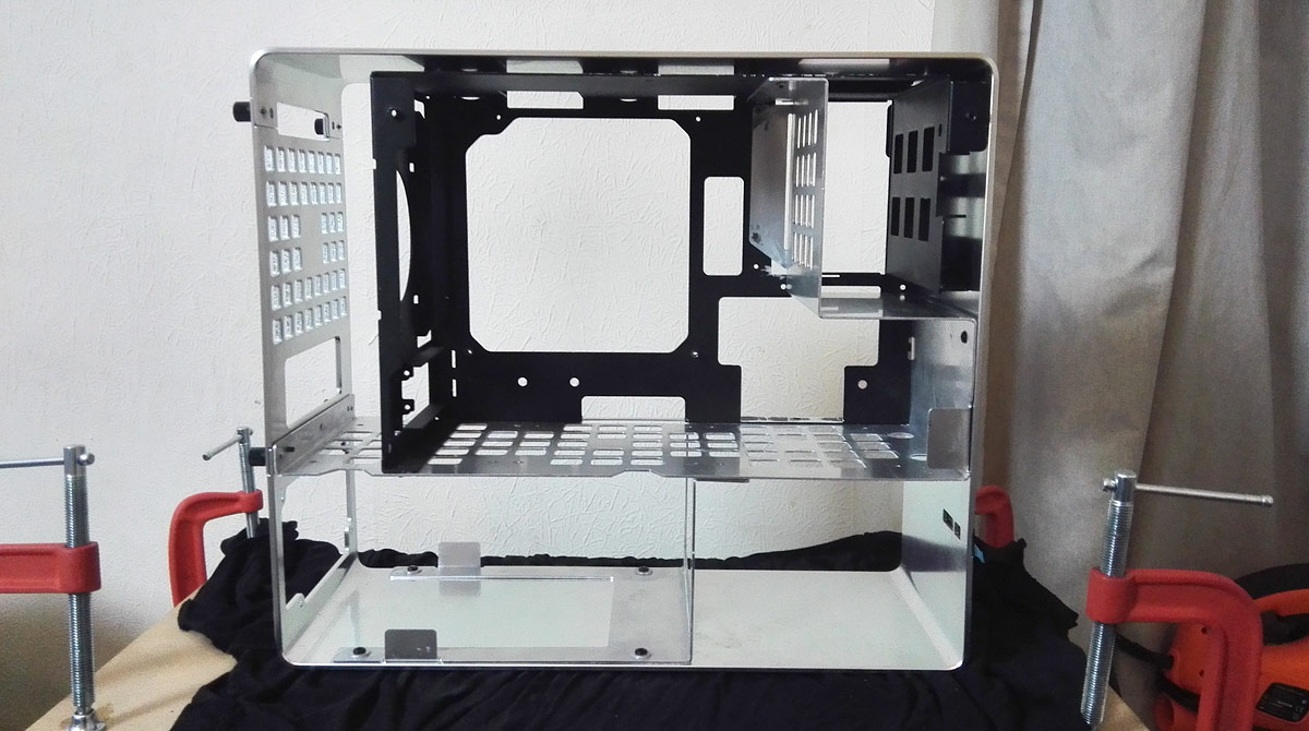
As far as the vice jaws go, I think I wasted my money if I'm honest because even if you get the wide one, you can only fold something that's no longer than the depth of the vice itself. For example, those awkward tabs you can see on the main body were longer than the depth of the vice, so it was bottoming out before I could even line the thing up. The deeper the vice, the more you can fit in. Ultimately I bodged it by clamping 2 lengths of iron angle to my workbench, putting the jaws on that and then slowly closing up the workbench. Did the job, but it's awkward.
So metal folder yes, vice jaws perhaps.
The reservoir mount has been redesigned actually, but I've always been planning something unobtrusive. Not sure if a friend has been able to wangle some laser cutting time for it so I'll have to cut it by hand, which will be a pain given it's mostly circular with very precise mounting holes in it!
Point taken about the vice jaws. Also it looks like it'll scratch the hell out of the sheets?
I remember reading somewhere that as a general rule of thumb, the bending radius of aluminium sheets is the same as the thickness - does this sound right?
I remember reading somewhere that as a general rule of thumb, the bending radius of aluminium sheets is the same as the thickness - does this sound right?
Thickness = radius is a good rule of thumb, but I've found that resistance also contributes. I've found if you have a lot of material along a fold then the radius will increase, conversely the radius will decrease if you're not bending much. For example, I'm using 1.5mm thick alu and the main body panels are about 160mm at their widest. I ended up with a bend radius a touch over 2mm along those bits. The tabs and such which are about 20mm or so wide actually folded much tighter at 0.5-1mm radius. Also the gauge of material you're folding has an effect too. I'm using 1050 gauge alu, but you can get more expensive stuff that has negligible radius.
You can also cut a channel along the fold line to bend tighter too, which is really useful if you're doing thicker sheets and still want tight bends.
As far as the scratches go, I've had more marks from the bender than the vice jaws. The bending brace is about 5mm thick, but has 45 degree edges on it to allow for over 90 degree bends (which you want to prevent springback). This means the folding edge is like a knife and cuts into the surface, so will require sanding down and cleaning up. I'm also scraping very thin layers of JB Weld into the deeper marks to act as a filler. Ultimately I'm powder coating so marks like that won't be an issue, but if you're going for a raw metal look or painting then you'll probably need extensive surface cleanup afterwards. Wet sand with 400 grit, 800 grit then maybe 1200 grit will smooth everything out.
I think my powder coating is going to be quite cheap. Local place reckons they can do all of my bits for about £40, maybe less. But to be honest, if you're painting properly then you're supposed to be sanding down the metal, multiple thin coats of primer, sanding the primer, multiple thin coats of paint, sand the paint, thin coat of protective.
Honestly, by the time you've done all that you would've filled in any surface imperfections with the primer so it probably sounds more daunting than it actually is. The worst marks I have you can feel with the tip of your fingernail, but you can't feel them with your actual fingertip. Then I sanded a few down to see and it's a non-issue. They are visible on the metal, but you can't feel it. Like I said, it's only really an issue if you plan on keeping a bare metal look, and even then you can buff it all out.
Don't be deterred.

I have a BIG update for you. Not so much in volume, but in significance. After 2 years of planning, design, redesign, stress and very scary moments I think I might actually have the case...
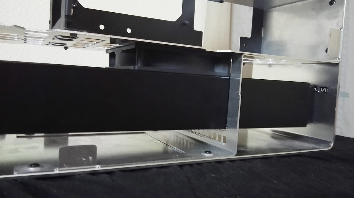
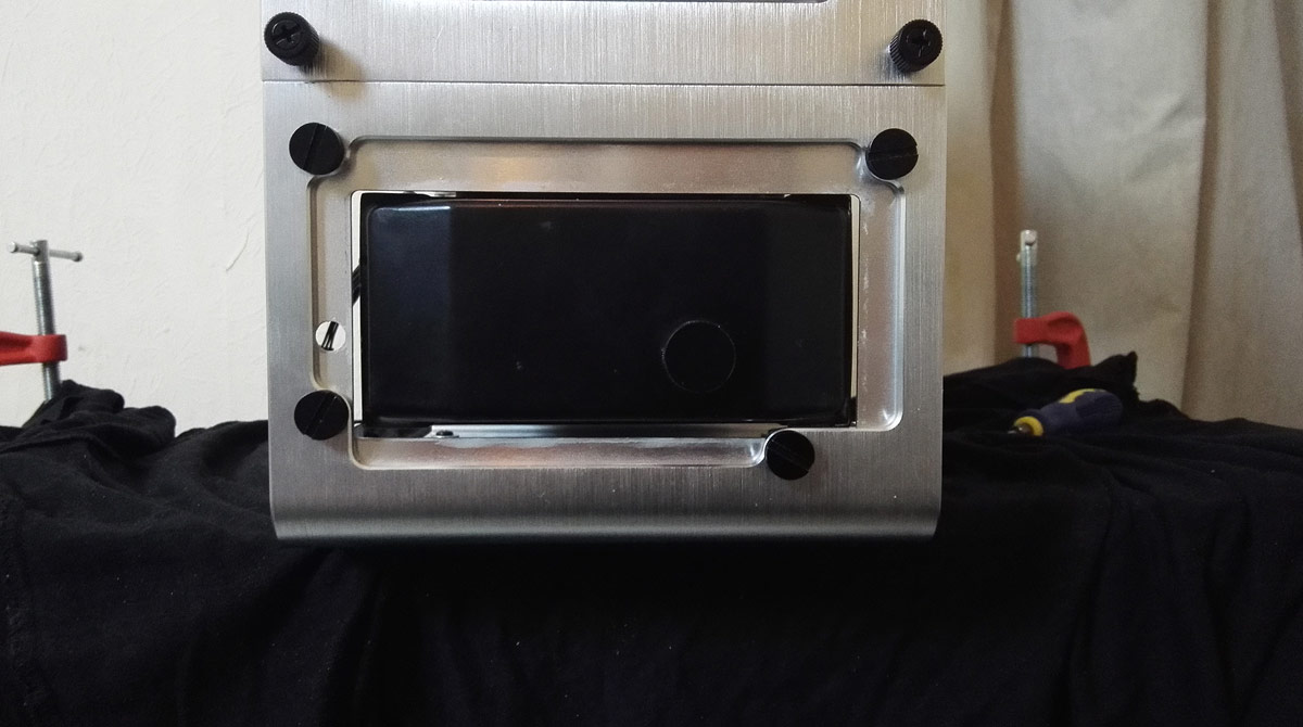
And for all those who asked the question directly, here is the big reveal: the Alphacool UT60 360 radiator mounted inside.
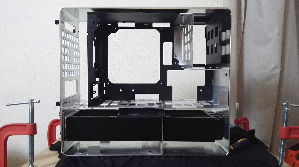
Close-up of the rad in situ
And after all the trouble with bending the lower L incorrectly, trashing all backup pieces, bend radii throwing measurements off and ultimately taking a hacksaw to lovely laser cut work...
It's turned out pretty much bang on. Hell, I might have even taken a tiny bit too much out!
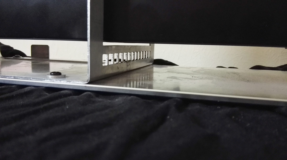
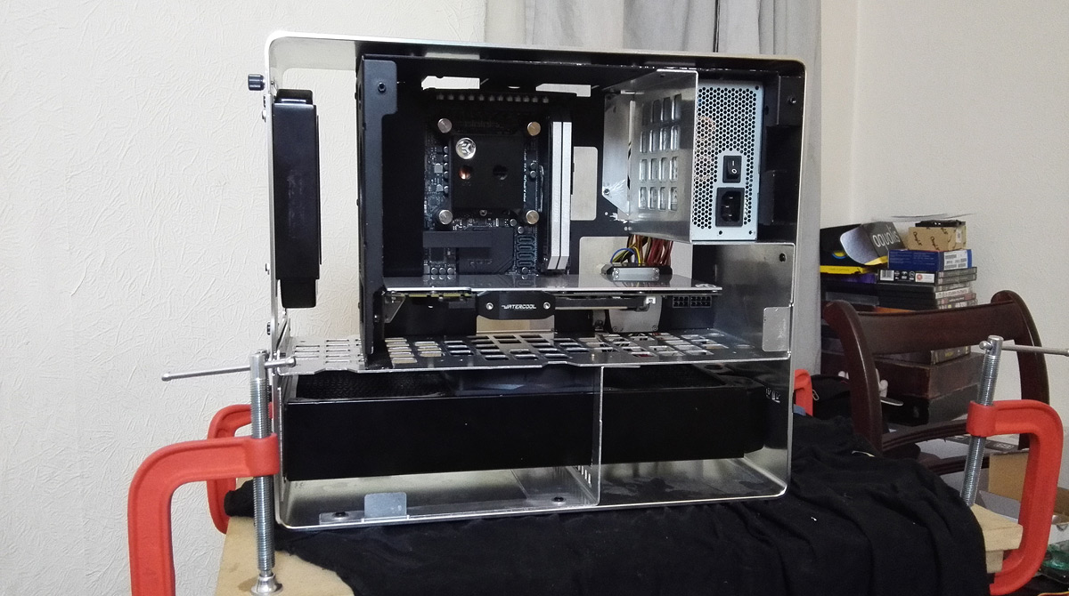
Things still need a bit of adjustment to straighten bits up, but here's a cheeky shot of the back with a vanity plate I put in to cover the PSU opening. Should look nice once cleaned up and brushed to replicate the case exterior.
And to wrap up, I simply had to throw the hardware into the case. Consider this a teaser and a spoiler for when everything comes together

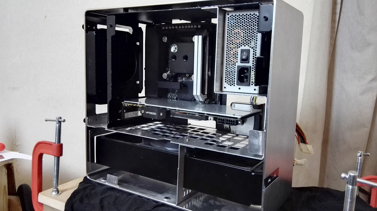
Forgive the grotty photos because I'm over-excited and over-tired! Still lots to do to get the case cleaned up and finalised, but I think finally I've now broken the back of it. The grunt work is done, so everything now is a million little things so I can potter about and do bits here and there, rather than have to schedule in large blocks of time.
Plenty more to do, plenty more to see, and plenty of things I've not even talked about yet

Stay tuned.
Last edited:
Things have gotten busy at home so I don't have anything of note to share on the build, but I've just found out this project has been nominated for bit-tech's monthly modding update.
That is scary and huge news for me. Even got a vote too, which is mindblowing considering the amazing quality of the other nominees
That is scary and huge news for me. Even got a vote too, which is mindblowing considering the amazing quality of the other nominees
Associate
- Joined
- 25 Aug 2013
- Posts
- 390
Damn, this is looking fantastic! And congratulations on the nomination, definitely deserved!
I can't wait to see the rest of the work to be done
I can't wait to see the rest of the work to be done
Cheers Frank, all the positive support is very much appreciated. Ideally I want to finish off some fiddly bits with the blanking plates on the lower half, but it's annoying me so I might leave it for a bit
With the PSU moving to where the hard drives originally sat, and no M.2 socket on the motherboard, you might be wondering "where will storage go now then?". That's the bit I want to show next, but I need to pull the trigger on LED strips and acrylic first")
With the PSU moving to where the hard drives originally sat, and no M.2 socket on the motherboard, you might be wondering "where will storage go now then?". That's the bit I want to show next, but I need to pull the trigger on LED strips and acrylic first
Greetings!
Not much to say at the minute as I'm trying to get some money together for the next phase of the project. Rather than let this log vanish into the ether, I thought I'd share a little preview of something upcoming. Very rough photos as this update has been thrown together rather hastily
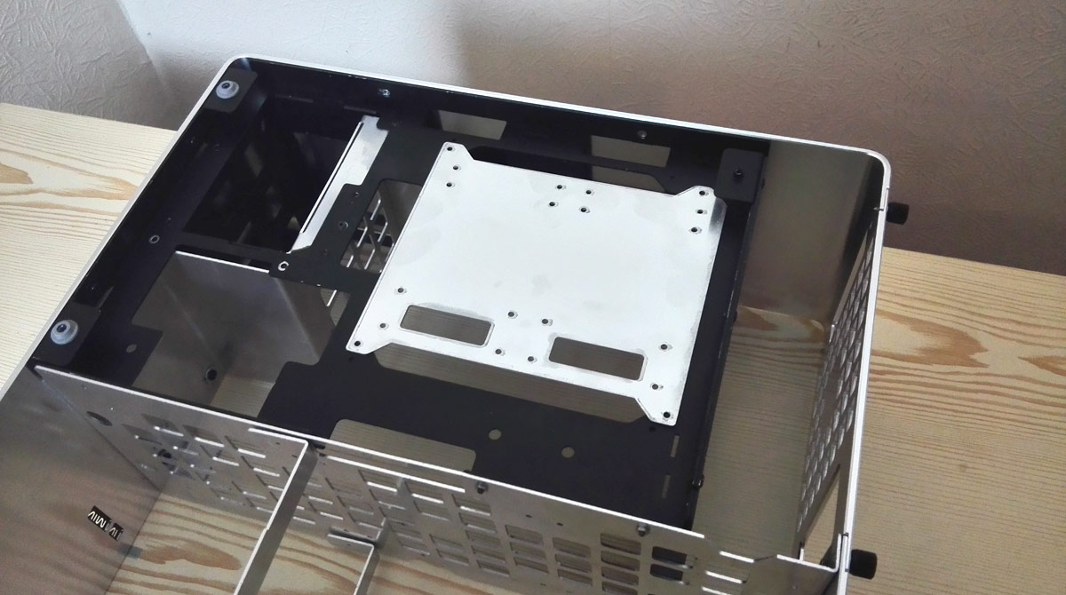
With the radiator occupying the entire lower chamber of the case, and the PSU residing where the hard drives would usually sit, I need to relocate the storage. Since I'm sticking with 2.5" drives right now, I thought I'd make the new drive position a bit of a feature. So, one drive mounting plate drawn up and cut:
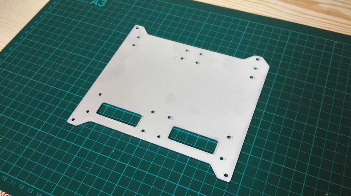
and will be placed on the back of the case over the motherboard cutout, something like this
Space for 2 drives; I'll be repurposing my existing Samsung 840 500GB as it's still in excellent health and pairing it with one of those slim 7mm tall laptop drives for file storage, more than likely the Western Digital WD10SPCX 1TB. Allow this battered Seagate to illustrate.
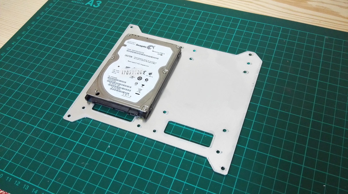
I'm going for a wireless look for this storage plate, so each drive has a cutout for running cables out of the way. I'll be using those ultra slim Silverstone CP11 SATA cables to tuck under the GPU, route under the motherboard and out the big case cutout into the storage plate. For power I'm going to try and make up a veroboard for sharing the power a few ways as I have something fancy planned (and is what's costing the money)
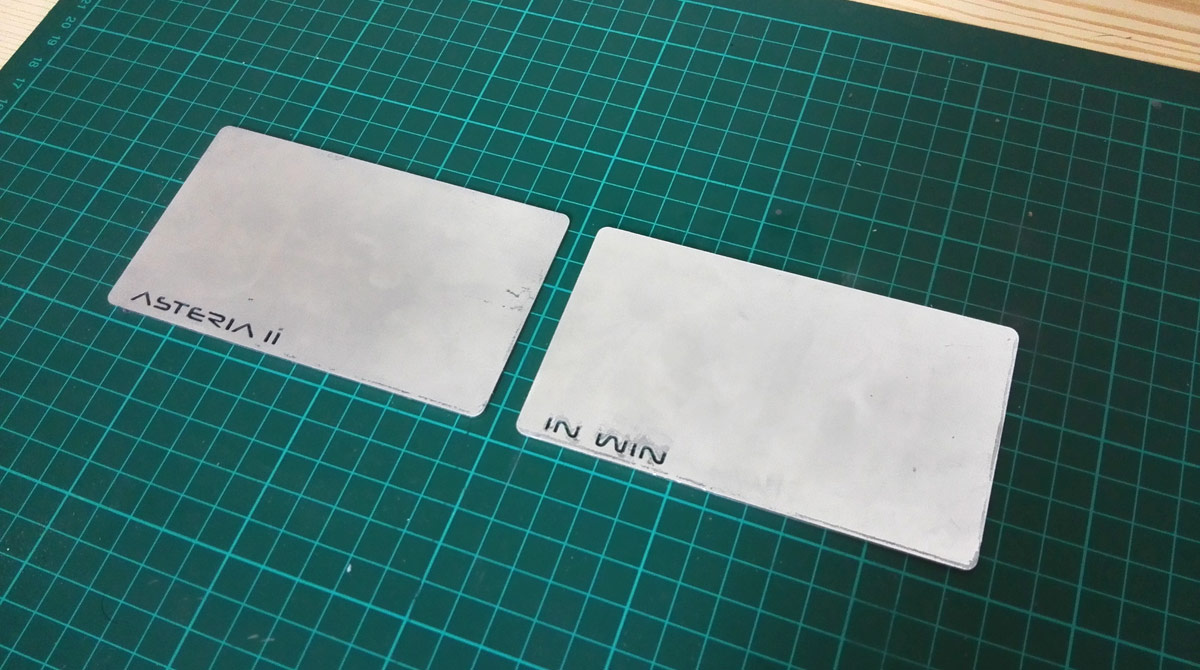
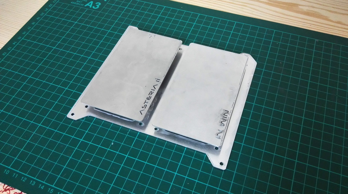
Given the visual mismatch of a mechanical dive paired with SSD, I'm not leaving the drives exposed. Pair of aluminium covers will be used, and I've cut the Asteria II and In Win branding into them for some visual flourish paired with something to come later.
It'll be along these lines when they're in position:
That's the general gist of it anyway
Hopefully I can scrounge some money together soon and get the acrylic and LED strips in and get this bit put together properly.
Catch you soon!
Not much to say at the minute as I'm trying to get some money together for the next phase of the project. Rather than let this log vanish into the ether, I thought I'd share a little preview of something upcoming. Very rough photos as this update has been thrown together rather hastily
With the radiator occupying the entire lower chamber of the case, and the PSU residing where the hard drives would usually sit, I need to relocate the storage. Since I'm sticking with 2.5" drives right now, I thought I'd make the new drive position a bit of a feature. So, one drive mounting plate drawn up and cut:
and will be placed on the back of the case over the motherboard cutout, something like this
Space for 2 drives; I'll be repurposing my existing Samsung 840 500GB as it's still in excellent health and pairing it with one of those slim 7mm tall laptop drives for file storage, more than likely the Western Digital WD10SPCX 1TB. Allow this battered Seagate to illustrate.
I'm going for a wireless look for this storage plate, so each drive has a cutout for running cables out of the way. I'll be using those ultra slim Silverstone CP11 SATA cables to tuck under the GPU, route under the motherboard and out the big case cutout into the storage plate. For power I'm going to try and make up a veroboard for sharing the power a few ways as I have something fancy planned
(and is what's costing the money)Given the visual mismatch of a mechanical dive paired with SSD, I'm not leaving the drives exposed. Pair of aluminium covers will be used, and I've cut the Asteria II and In Win branding into them for some visual flourish paired with something to come later.
It'll be along these lines when they're in position:
That's the general gist of it anyway
Hopefully I can scrounge some money together soon and get the acrylic and LED strips in and get this bit put together properly.
Catch you soon!
Last edited:
Many thanks, Plec, good to have you onboard.
Acrylic has arrived, 3D models finalised, new CAD drawings wrapped up, all I need to do now is get up to my local maker space and get the stuff chopped up and printed! Hopefully I'll have something new to show this time next week.
Acrylic has arrived, 3D models finalised, new CAD drawings wrapped up, all I need to do now is get up to my local maker space and get the stuff chopped up and printed! Hopefully I'll have something new to show this time next week.
Soldato
- Joined
- 2 Aug 2016
- Posts
- 4,299
- Location
- Third Earth
@LePhuronn - You're very talented
OK, I have a few things in the works now and hopefully I'll get a few little bits up over the weekend after I've done my acrylic cutting.
In light of my pump placement issues and discussion on another thread I've decided to have a crack at making my own DDC top doing exactly what I need it to do. This is the pump top I came up with:
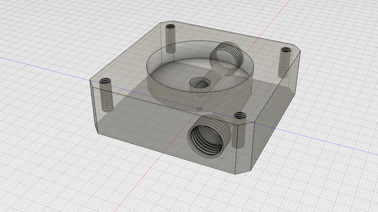
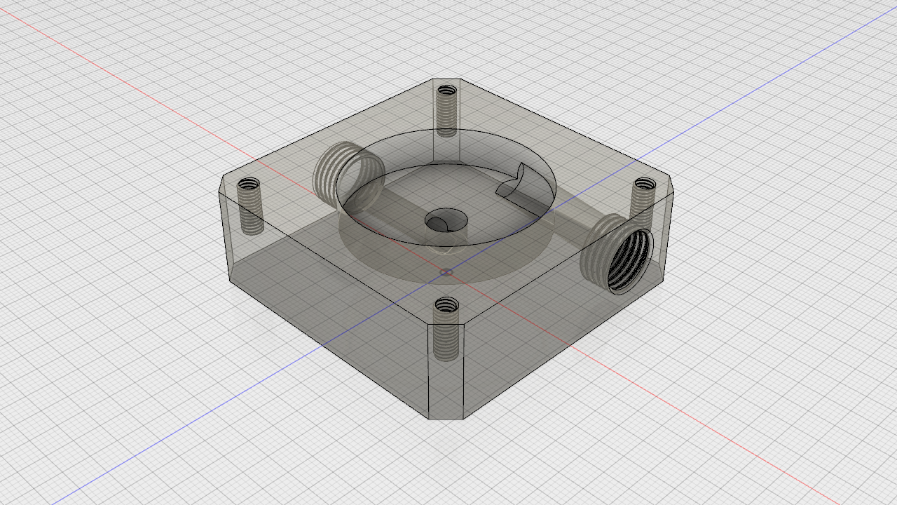
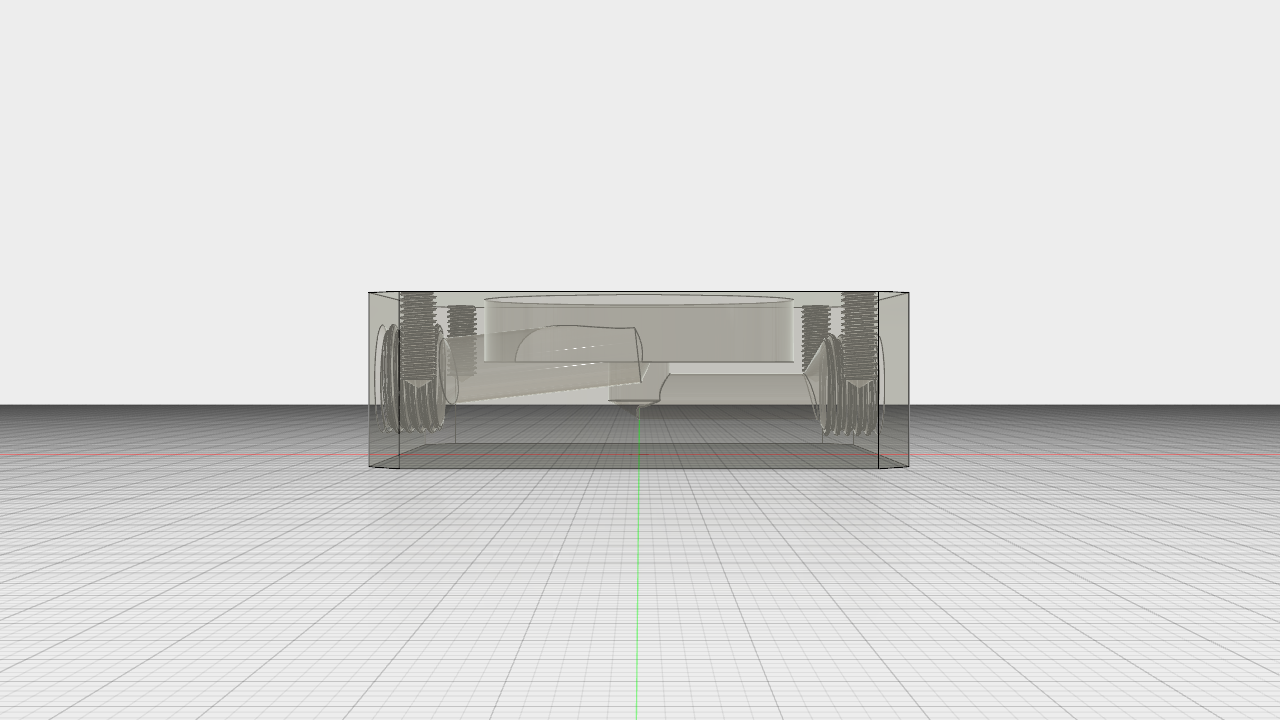
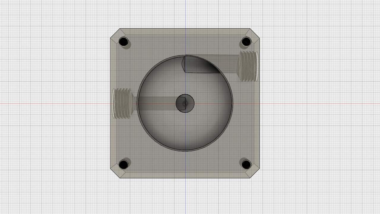
It's based around what I can theoretically do with a drill press and some careful measurements, so no spiral volute this time. I'm milling the volute out with a forstner bit so I could, in theory, offset the centre a bit a couple of times to fake a spiral, but it won't be smooth and would probably just end up causing turbulence before the water even exits the top, doing an even worse job than just a circular volute.
I grabbed some offcut white acetal for a test and have drawn out quite a few drilling guides that I'll be making up in acrylic. All I need to do is build my pillar drill and I can give it a whirl!
If this works then loop routing is much easier and I'll have no conflicts with the graphics card so can raise and lower the entire pump as required. I'll then address the heatsink at a later date.
In light of my pump placement issues and discussion on another thread I've decided to have a crack at making my own DDC top doing exactly what I need it to do. This is the pump top I came up with:
It's based around what I can theoretically do with a drill press and some careful measurements, so no spiral volute this time. I'm milling the volute out with a forstner bit so I could, in theory, offset the centre a bit a couple of times to fake a spiral, but it won't be smooth and would probably just end up causing turbulence before the water even exits the top, doing an even worse job than just a circular volute.
I grabbed some offcut white acetal for a test and have drawn out quite a few drilling guides that I'll be making up in acrylic. All I need to do is build my pillar drill and I can give it a whirl!
If this works then loop routing is much easier and I'll have no conflicts with the graphics card so can raise and lower the entire pump as required. I'll then address the heatsink at a later date.
Last edited: